
Manuels Connexes pour Stryker InTouch Critical Care Bed


Sommaire des Matières pour Stryker InTouch Critical Care Bed
- Page 1 InTouch® Critical Care Bed FL27 (2131/2141) Upgraded from version 2.x - 3.1 to 4.0 Operations Manual 2014/08 A.0 2141-800 -107 REV A www.stryker.com...
- Page 2 sample text...
-
Page 3: Intouch® Critical Care Bed
InTouch® Critical Care Bed FL27 (2131/2141) Upgraded from version 2.x - 3.1 to 4.0 Operations Manual 2014/08 A.0 2141-800 -107 REV A www.stryker.com... - Page 4 sample text...
- Page 5 Equipment, this symbol indicates that the product must not be disposed of as unsorted municipal waste, but should be collected separately. Refer to your local distributor for return or collection systems available in your country. www.stryker.com 2141-800-1 07 REV A...
- Page 6 Symbols English Non-ionizing radiation such as RF transmitter (Wi-Fi) iBed Locator is connected iBed Locator is not connected Wireless Network is connected Wireless Network is not connected Support surface call maintenance 2141-800-1 07 REV A www.stryker.com...
-
Page 7: Table Des Matières
Table of Contents English Warning/Caution/Note Definition........................ 1-5 Introduction ............................1-6 Product description ........................... 1-6 Intended use: InTouch Critical Care bed ....................1-6 Intended use: iBed Wireless ® with iBed Awareness .................. 1-7 Expected service life ......................... 1-7 Contraindications..........................1-7 Specifications..........................1-7 Product illustration .......................... - Page 8 Turning Low Air Loss (LAL) on or off ....................1-74 Viewing and clearing history......................1-74 Support surface malfunctioning ......................1-75 Main menu: Options ........................1-76 Setting the time and date ......................... 1-77 Configuring Smart TV (optional)......................1-77 2141-800-1 07 REV A www.stryker.com...
- Page 9 Installing the optional patient control pendant..................1-113 Installing the optional traction sleeves ....................1-114 Installing the optional wall saver......................1-115 Installing the optional X-ray cassette holder..................1-116 Cleaning............................1-117 Cleaning a support surface......................1-117 Preventive Maintenance........................1-118 Warranty ............................1-120 Limited warranty ..........................1-120 Warranty exclusion and damage limitations..................1-120 www.stryker.com 2141-800-1 07 REV A...
- Page 10 Table of Contents English To obtain parts and service......................1-120 Return authorization........................1-120 Damaged product ..........................1-120 International warranty clause ......................1-120 2141-800-1 07 REV A www.stryker.com...
-
Page 11: Warning/Caution/Note Definition
Note: Provides special information to make maintenance easier or important instructions clearer. www.stryker.com 2141-800-1 07 REV A... -
Page 12: Introduction
Stryker continually seeks advancements in product design and quality. Therefore, while this manual contains the most current product information available at the time of printing, there may be minor discrepancies between your product and this manual. If you have any questions, contact Stryker Customer Service or Technical Support at 1- 800-327-0 770. -
Page 13: Intended Use: Ibed Wireless With Ibed Awareness
The intended use for the iBed Wireless (with iBed Awareness) is to assist clinical staff to monitor bed parameters on specific Stryker beds. The desired bed parameters are set by operators at the bedside. The iBed Wireless software is only intended for use with specifically enabled Stryker beds that have been verified and validated with the iBed Wireless software, and is not intended to provide bed status information for non-Stryker beds. - Page 14 ± 2 lb when in Trendelenburg or Reverse Trendelenburg • For weight under 100 lb ± 2 lb when flat Speed to level product from any position • 15 seconds CPR system • Fowler • 60 seconds • Foot and seat 2141-800-1 07 REV A www.stryker.com...
- Page 15 Isolibrium™) (35 in. x 6 in. x 4 in.) With Bed Extender DM64197 88,9 cm x 228,6 cm x 13,9 cm 35 in. x 90 in. x 5.5 in. (XPRT™) (35 in. x 6 in. x 5.5 in.) www.stryker.com 2141-800-1 07 REV A...
- Page 16 (25 °C) Scale accuracy 64 °F (18 °C) Specifications listed are approximate and may vary slightly from product to product or by power supply fluctuations. Stryker reserves the right to change specifications without notice. 1-10 2141-800-1 07 REV A www.stryker.com...
-
Page 17: Product Illustration
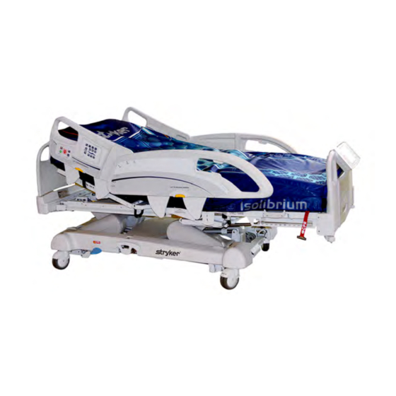
Introduction English Product illustration Figure 1-1: InTouch Critical Care bed 110V outlet (optional) Manual backup brake Brake control panel (outside siderail) Mattress retainer Nurse call (inside siderail) (option) Caster Motion control panel (outside siderail) CPR release pedal Foley bag hooks... -
Page 18: Contact Information
Stryker Medical 3800 E. Centre Avenue Portage, MI 49002 Have the serial number (A) of your Stryker product available when calling Stryker Customer Service or Technical Support. Include the serial number in all written communication. Serial number location You can find the serial number plate behind the patient right siderail near the foot end of the product. -
Page 19: Summary Of Safety Precautions
• Always keep feet clear from the area above the base cover or below the base cover when lowering the product or when applying the brakes or releasing the brakes. www.stryker.com 2141-800-1 07 REV A 1-13... - Page 20 Always determine the proper use of the restraint straps and restraint strap locations. Improperly adjusted restraint straps can cause serious injury to a patient. Stryker is not responsible for the type or use of restraint straps on any of Stryker’s products.
- Page 21 • Always immediately replace batteries that have corrosion at the terminals, display cracking, have expanded or bulging sides, or no longer can maintain a full charge. www.stryker.com 2141-800-1 07 REV A 1-15...
- Page 22 English CAUTION (CONTINUED) • Always use only Stryker authorized batteries when replacing the batteries. Use of non-Stryker batteries may lead to unpredictable system performance. • Upon a Battery Low alarm (Battery Low LED on Footboard and audible beep), stop using the Zoom motorized drive and recharge the batteries immediately.
-
Page 23: Setup
Always unplug the product power cord from the wall when using oxygen administering equipment. Possible fire hazard exists when this product is used with oxygen administering equipment other than nasal, mask type, or half bed-length tent type. www.stryker.com 2141-800-1 07 REV A 1-17... -
Page 24: Installation
You must also remap the iBed Locator if you change the room or location information after initial installation. If you have any problems during the iBed Wireless installation process, contact Stryker Technical Support at 1-800-327 −0770. -
Page 25: Operation
Always immediately replace batteries that have corrosion at the terminals, display cracking, have expanded or bulging sides, or no longer can maintain a full charge. • Always use only Stryker authorized batteries when replacing the batteries. Use of non-Stryker batteries may lead to unpredictable system performance. •... -
Page 26: Applying Or Releasing The Manual Brake
To release the manual brakes, depress the pedal until Neutral or Drive appears in the brake pedal window (B) (Figure 1- 6 on page 1-21). Note: If you set the brakes manually, they can be released electronically. 1-20 2141-800-1 07 REV A www.stryker.com... - Page 27 Operation English Applying or releasing the manual brake (Continued) Figure 1-4: Manual brake pedal Figure 1-5: Flipped manual brake pedal Figure 1-6: Brake pedal window www.stryker.com 2141-800-1 07 REV A 1-21...
-
Page 28: Applying Or Releasing The Electric Brakes
Footboard control panel on page 1-37), or head end control panel (optional) (see Head end control panel (optional) on page 1-36). To transport InTouch with steer lock, press D/Drive. To release steer lock, press N/Brake Off. 1-22 2141-800-1 07 REV A www.stryker.com... -
Page 29: Transporting Intouch By Using The Zoom Motorized Drive (Model 2141) (Option)
Press D/Drive on the brake control panel, footboard control panel, or head end control panel (optional). Note: The D/Drive button illuminates when the drive wheel is activated. Make sure that the product is ready for driving. www.stryker.com 2141-800-1 07 REV A 1-23... - Page 30 11. To slow down, push or pull the handles in the opposite direction the product is currently moving. 12. To stop motion, you must release both triggers on the drive handles. WARNING Do not use the brake to slow or stop the product while it is in motion. 1-24 2141-800-1 07 REV A www.stryker.com...
-
Page 31: Activating The Cpr Release Pedal
Two instant CPR release pedals are located at the head end section on both the left and right sides of the litter (A) (Figure 1-9 on page 1-25). To activate the CPR release pedal, fully depress the CPR pedal. The product instantly flattens to 0°. Figure 1-9: CPR release pedal www.stryker.com 2141-800-1 07 REV A 1-25... -
Page 32: Locating The Foley Bag Hooks
There are four foley bag hooks under the fowler section (A) and foot section (C) on both sides of the product (Figure 1- 10 on page 1-26). If you weigh the patient with the scale system, the foley bag weight is included with the patient weight. Figure 1-10: Foley bag hooks 1-26 2141-800-1 07 REV A www.stryker.com... -
Page 33: Locating The Patient Restraint Strap Tie-Ins
Always determine the proper use of the restraint straps and restraint strap locations. Improperly adjusted restraint straps can cause serious injury to a patient. Stryker is not responsible for the type or use of restraint straps on any of Stryker’s products. -
Page 34: Operating Nurse Call (Option)
1-28). A 5A breaker is also integrated into this power outlet. Note: To install a support surface option onto InTouch, see the installation instructions in the support surface operations manual. Figure 1-12: Optional InTouch auxiliary outlets 1-28 2141-800-1 07 REV A www.stryker.com... -
Page 35: Removing Or Replacing The Headboard
To replace the headboard, align the bottom of the headboard with the pegs at the head end of the product, and then lower the headboard until it completely seats onto the pegs (Figure 1-14 on page 1-29). Figure 1-14: Replacing the headboard Figure 1-13: Removing the headboard www.stryker.com 2141-800-1 07 REV A 1-29... -
Page 36: Removing Or Replacing The Footboard
To replace the footboard, lower the footboard onto the footboard connector. Make sure that the footboard properly fits onto the footboard connector on the foot end of the litter (Figure 1-16 on page 1-30). Figure 1-15: Removing the footboard Figure 1-16: Replacing the footboard 1-30 2141-800-1 07 REV A www.stryker.com... -
Page 37: Raising Or Lowering The Siderails
(Figure 1-17 on page 1-31) and rotate the siderail backward. To lower the siderails, grasp the yellow release latch (A) (Figure 1-17 on page 1-31) and rotate the siderail forward. Figure 1-17: Raising or lowering the siderails www.stryker.com 2141-800-1 07 REV A 1-31... -
Page 38: Motion Control Panel (Outside Siderail)
Raises the fowler section Fowler down Lowers the fowler section Raises the gatch section Gatch up Lowers the gatch section Gatch down Foot up Raises the foot section Foot down Lowers the foot section 1-32 2141-800-1 07 REV A www.stryker.com... - Page 39 The maximum angle of inclination during the Trendelenburg and reverse Trendelenburg position is 15°. • You must have a minimum clearance of 20 in. for the Trendelenbu rg and Reverse Trendelenburg positions. • You can lower the height while in Trendelenburg without changing the angle. www.stryker.com 2141-800-1 07 REV A 1-33...
-
Page 40: Brake Control Panel (Outside Siderail)
Brake set LED Flashes amber when you release the brakes Brake not set LED Raises the foot section to the vascular position Vascular Position HOB 30° position Raises the fowler section/head of bed (HOB) to 30° 1-34 2141-800-1 07 REV A www.stryker.com... -
Page 41: Patient Control Pendant (Optional)
Turns the reading light on or off Nurse call Activates nurse call Gatch up Raises the gatch section Lowers the gatch section Gatch down Fowler up Raises the fowler section Fowler down Lowers the fowler section www.stryker.com 2141-800-1 07 REV A 1-35... -
Page 42: Head End Control Panel (Optional)
Raises the fowler section Fowler down Lowers the fowler section Raises the gatch section Gatch up Lowers the gatch section Gatch down Foot up Raises the foot section Foot down Lowers the foot section 1-36 2141-800-1 07 REV A www.stryker.com... -
Page 43: Footboard Control Panel
Model 2131: releases the brakes and the steer function • Model 2141: releases the brakes and deactivates the Zoom Neutral/Brake Off (N/Brake motorized drive Off) Note: The N/Brake Off button and Brake Not Set LED illuminate when you release the brakes. www.stryker.com 2141-800-1 07 REV A 1-37... -
Page 44: Footboard Led Indicators
Illuminates amber when the product requires maintenance or repairs. Contact the appropriate maintenance personnel to restore proper functionality. Locks enabled Illuminates amber on the footboard control panel when one lock or a total lockout is set (see Main menu: Lockouts on page 1-86). 1-38 2141-800-1 07 REV A www.stryker.com... -
Page 45: Accessing Functions And Features With The Touch Screen Display And Navigation Bar
To awaken the touch screen from sleep mode, press any button on the footboard control panel, or tap the touch screen display. Note: The touch screen display shows the Patient Information screen by default when it awakes from sleep mode. www.stryker.com 2141-800-1 07 REV A 1-39... -
Page 46: Main Menu: Patient Information
View the Wi-Fi connection status (Figure 1-95 on page 1-84) iBed Locator (Optional) View the iBed Locator connection status (Figure 1-98 on page 1-85) Copyright. Barbara Braden and Nancy Bergstrom, 1988. Reprinted with permission. 1-40 2141-800-1 07 REV A www.stryker.com... -
Page 47: Clearing And Entering New Patient Information
(activated) when tapped. 2. Tap Ok. To enter a new Patient ID: 1. Tap the pencil (Figure 1-20 on page 1-41). 2. Enter the Patient ID. Figure 1-20: New patient 3. Tap Ok. www.stryker.com 2141-800-1 07 REV A 1-41... -
Page 48: Configuring The Visibility Of Patient Information
If no score has been measured, dashes are displayed for the missing value. Display Patient ID: Displays the Patient ID. You can enter the Patient ID on the New Patient screen (Figure 1-20 on page 1-41). 1-42 2141-800-1 07 REV A www.stryker.com... -
Page 49: Main Menu: Bed Controls
/ foot up) Angle indicator Shows the angle of Trendelenburg or Reverse Trendelenburg HOB angle indicator Shows the angle of head of bed (HOB) Battery power indicator Shows the power left in the battery www.stryker.com 2141-800-1 07 REV A 1-43... -
Page 50: Main Menu: Scale
• Power save mode activates after one hour on battery power with no motion release switch activation. Bed exit, scale, and product motion stops operating when the product enters the power save mode. 1-44 2141-800-1 07 REV A www.stryker.com... -
Page 51: Recording Patient Weight With A Delay
3. Return the equipment to its original position. To change the displayed measuring unit, tap lbs/kg (Figure 1-23 on page 1-45). To return to the Scale screen, tap Close (Figure 1-23 on Figure 1-23: Delayed Weight page 1-45). www.stryker.com 2141-800-1 07 REV A 1-45... -
Page 52: Setting The Scale To Zero
Figure 1-25: Do not touch bed A confirmation notification indicates that setting the scale to zero was successful (Figure 1-26 on page 1-46). Message Ze r o s u c c e s s ! Figure 1-26: Zero success! 1-46 2141-800-1 07 REV A www.stryker.com... -
Page 53: Viewing Weight History
4. To return to the Weight History screen, tap Cancel (Figure 1-28 on page 1-47). P r e v io u s N e x t Ca n c e l Figure 1-28: Weight history information www.stryker.com 2141-800-1 07 REV A 1-47... -
Page 54: Changing The Patient Weight
To decrease patient weight by 1.0 (lb or kg), hold the down arrow. • To save the desired weight, tap Ok. • To cancel the request, tap Cancel. Ca n c e l Figure 1-31: Change patient weight 1-48 2141-800-1 07 REV A www.stryker.com... -
Page 55: Measuring Weight Gain Or Loss
(Figure 1-34 on page 1-49). Message Gain Or Loss r e s e t s u c c e s s ! Figure 1-34: Gain or loss reset success! www.stryker.com 2141-800-1 07 REV A 1-49... -
Page 56: Main Menu: Chaperone Bed Exit
Bed exit is not designed to be used with patients weighing less than 50 lb (23 kg). • Power save mode activates after one hour on battery power with no motion release switch activation. Bed exit, scale, and product motion stops operating when the product enters the power save mode. 1-50 2141-800-1 07 REV A www.stryker.com... -
Page 57: Arming Or Disarming Chaperone Bed Exit
(Figure 1-101 on page 1-91 Note: If InTouch is equipped with the optional iAudio feature, voice alarms are available. Voice alarms replace the buzzer alarm and play through the inside siderail speakers. To disarm bed exit, tap Disarm. www.stryker.com 2141-800-1 07 REV A 1-51... -
Page 58: Setting The Alarm Tones
Name Function Volume down Decreases the volume Volume up Increases the volume Change tone Scrolls to the next tone Change tone Scrolls to the previous tone Tests the selected volume and tone setting Test 1-52 2141-800-1 07 REV A www.stryker.com... -
Page 59: Connecting A Support Surface To Intouch
. P le a s e c h e c k c a b le c o n n e c t io n s Figure 1-36: No mattress detected Figure 1-37: Navigation Bar www.stryker.com 2141-800-1 07 REV A 1-53... -
Page 60: Xprt Therapy Support Surface (Optional)
CAUTION Always use extra supervision when using a mattress or support surface thicker than six in. (15,4 cm). Figure 1-39: PositionPRO home screen on InTouch 1-54 2141-800-1 07 REV A www.stryker.com... -
Page 61: Restarting A Support Surface Function
Figure 1-40: System reset message • The Pressure Redistribution settings for Isolibrium are preserved when the product resets. • The settings for Protocol Reminders are lost when the product resets. www.stryker.com 2141-800-1 07 REV A 1-55... -
Page 62: Isolibrium Support Surface (Optional)
Pressure Redistribution, Lateral Rotation, and Turn Assist are not available until after you complete the Weight Range selection through the Surface Settings screen. • When you tap to select an icon, the icon illuminates orange. 1-56 2141-800-1 07 REV A www.stryker.com... -
Page 63: Preparing Isolibrium For A New Patient
There are two options for clearing the therapy history and are located: • New Patient display • Surface settings display (see Selecting to retain or clear therapy history on page 1-61). Figure 1-42: InTouch New Patient screen www.stryker.com 2141-800-1 07 REV A 1-57... -
Page 64: Positioning A Patient On The Support Surface
3. Check the patient frequently during Lateral Rotation for proper positioning and support surface inflation (Figure 1- 44 on page 1-58 Figure 1-45 on page 1-58). Figure 1-43: Center the patient Figure 1-44: Correct patient positioning Figure 1-45: Incorrect patient positioning 1-58 2141-800-1 07 REV A www.stryker.com... -
Page 65: Preparing Bed Positions For Support Surface Functions
Pressure Redistribution provides firmness for the patient based on the weight range and firmness settings. To initialize Pressure Redistribution: Tap Pressure Redistribution on the Pressure Redistribution screen (Figure 1-46 on page 1-59). Figure 1-46: Pressure redistribution www.stryker.com 2141-800-1 07 REV A 1-59... -
Page 66: Selecting Patient Weight Range
Patient weight is presented in pounds or kilograms based on the InTouch selection. • The patient weight range selection is between 50 lb and 460 lb (22.7 kg and 208.7 kg) and is used as input for Pressure Redistribution. 1-60 2141-800-1 07 REV A www.stryker.com... -
Page 67: Selecting To Retain Or Clear Therapy History
(Figure 1-49 on page 1-61). Tap Firm to increase the firmness setting (Figure 1-49 on page 1-61). Figure 1-49: Pressure redistribution Note: Always confirm patient weight (see Selecting patient weight range on page 1-60). www.stryker.com 2141-800-1 07 REV A 1-61... -
Page 68: Preparing For Lateral Rotation
Lateral Rotation will not function if the siderails are down. However, Pressure Redistribution, Max Inflate and Turn Assist will still activate without the siderails up. If a siderail is lowered or unlocked during Lateral Rotation, the function will automatically stop. 1-62 2141-800-1 07 REV A www.stryker.com... -
Page 69: Starting Lateral Rotation
Raise all of the siderails to allow Lateral Rotation to start. Note: If you do not raise all of the siderails, a notification will display (Figure 1-52 on page 1-64). Tap OK to return to the previous screen. www.stryker.com 2141-800-1 07 REV A 1-63... - Page 70 Figure 1-54 on page 1-64). Tap OK to return to the previous screen. Figure 1-53: Notification HOB angle setting for any Figure 1-54: Notification HOB angle setting for full rotation rotation Tap Start to initiate. 1-64 2141-800-1 07 REV A www.stryker.com...
-
Page 71: Starting A One-Sided Lateral Rotation
To resume lateral rotation for a paused state, tap Start (Figure 1-57 on page 1-65). To stop lateral rotation at any time, tap Stop. Figure 1-56: Lateral rotation screen Figure 1-57: Lateral rotation paused www.stryker.com 2141-800-1 07 REV A 1-65... - Page 72 Lateral Rotation will continue until you stop, pause the function, or reach the time limit of 100 hours. • All therapy parameters are stored in the history until you clear the history (see Selecting to retain or clear therapy historyon page 1-61). 1-66 2141-800-1 07 REV A www.stryker.com...
-
Page 73: Changing Head Of Bed Angle During Lateral Rotation
Lateral Rotation has been cancelled ( Figure 1-60 on page 1-67). To return to the Lateral Rotation screen, tap OK. Figure 1-59: Lateral rotation total time elapsed Figure 1-60: Lateral rotation duration time reached www.stryker.com 2141-800-1 07 REV A 1-67... -
Page 74: Starting And Stopping Turn Assist
30 min 120 min Note: Make sure that the head of bed (HOB) angle is less than or equal to 60° to avoid the therapy cannot be started notification (Figure 1-62 on page 1-69). 1-68 2141-800-1 07 REV A www.stryker.com... - Page 75 Note: When inflation is complete, the Turn Assist time remaining window is displayed and the selections are gray (Figure 1-64 on page 1-69). The timer will count down to zero and then the support surface deflates. To stop Turn Assist, tap Stop. www.stryker.com 2141-800-1 07 REV A 1-69...
-
Page 76: Starting And Stopping Max Inflate
30 min Figure 1-66: Max inflate hold time selected Tap Start to begin Max Inflate and hold for the time selected. Note: The Inflation in progress window is displayed (Figure 1-67 on page 1-71). 1-70 2141-800-1 07 REV A www.stryker.com... - Page 77 When inflation is complete, the Max Inflate duration window is displayed and the selections are gray (1-68 Max inflate time remaining on page 1-71). The timer will count down to zero. Figure 1-68: Max inflate time remaining To stop max inflate, tap Stop. www.stryker.com 2141-800-1 07 REV A 1-71...
-
Page 78: Activating And Resetting Cpr
To reset the CPR straps, pull down on the CPR straps until they snap back into their fully seated position. To reset the InTouch CPR release pedal, tap OK (Figure 1-71 on page 1-72). 1-72 2141-800-1 07 REV A www.stryker.com... -
Page 79: Cancelling Functions
To unlock all of the support surface functions, tap Lock which is located at the top of the Support Surface display (Figure 1-74 on page 1-73). Figure 1-74: Unlocked Note: Inactive lock is white. www.stryker.com 2141-800-1 07 REV A 1-73... -
Page 80: Turning Low Air Loss (Lal) On Or Off
Figure 1-78 on page 1-74). Figure 1-77: Therapy history button To clear therapy history, tap Clear History. To exit therapy history, tap X or tap Therapy History. Figure 1-78: View history or clear history 1-74 2141-800-1 07 REV A www.stryker.com... -
Page 81: Support Surface Malfunctioning
If the support surface malfunction message is displayed (Figure 1-81 on page 1-75): 1. Immediately remove the patient from the support surface. 2. Immediately remove the product from service. 3. Contact the appropriate maintenance personnel. www.stryker.com 2141-800-1 07 REV A 1-75... -
Page 82: Main Menu: Options
Activate or deactivate alarms for Bed Exit, iBed Awareness, and Advanced Options Protocol Reminders Wi-Fi (Optional) View the Wi-Fi connection status (Figure 1-95 on page 1-84) iBed Locator (Optional) View the iBed Locator connection status (Figure 1-98 on page 1-85) 1-76 2141-800-1 07 REV A www.stryker.com... -
Page 83: Setting The Time And Date
Ca n c e l To cancel the request, tap Cancel (Figure 1-83 on page 1-77). Figure 1-83: Smart TV configuratio n Note: The request is cancelled if the bed goes into auto shutoff. www.stryker.com 2141-800-1 07 REV A 1-77... -
Page 84: Changing The Displayed Screen Language
Main menu: Options on page 1-76). Tap the desired language (Figure 1-84 on page 1-78). Note: Options change from blue (deactivated) to green (activated) when tapped. Tap Close (Figure 1-84 on page 1-78). Figure 1-84: Language 1-78 2141-800-1 07 REV A www.stryker.com... -
Page 85: Viewing Parameter History
(Figure 1-86 on page 1-79). To reset the stored angle histories, tap Reset (Figure 1- 87 on page 1-79). To return to the History screen, tap Close (Figure 1-87 on page 1-79). Figure 1-87: Angle History www.stryker.com 2141-800-1 07 REV A 1-79... - Page 86 (Figure 1-89 on page 1-80). To reset the stored height histories, tap Reset (Figure 1- 89 on page 1-80). To return to the History screen, tap Close (Figure 1-89 Figure 1-89: Height History on page 1-80). 1-80 2141-800-1 07 REV A www.stryker.com...
-
Page 87: Changing The Control Panel Led Backlight Intensity
1-76). 2. Tap the left or right arrow (Figure 1-90 on page 1-81). Figure 1-90: Nurse control LED intensity 3. To save the LED intensity setting, tap Close (Figure 1- 90 on page 1-81). www.stryker.com 2141-800-1 07 REV A 1-81... -
Page 88: Viewing General Maintenance Status Information
To return to the Options screen, tap Close (Figure 1-91 Clo s e on page 1-82). To return to the Maintenance screen, tap Back. Figure 1-91: Maintenance Figure 1-92: Error Codes Figure 1-93: Signal Values 1-82 2141-800-1 07 REV A www.stryker.com... -
Page 89: Viewing Advanced Alarm Options
If InTouch is equipped with the optional iAudio feature, voice alarms are available. Voice alarms replace the buzzer alarm and play through the inside siderail speakers. To return to the Options main menu, tap Back (Figure 1- 94 on page 1-83). www.stryker.com 2141-800-1 07 REV A 1-83... -
Page 90: Viewing The Wi-Fi Connection Status (Optional)
• The settings for Protocol Reminders are lost when you reset the product. To cancel the request, tap Cancel (Figure 1-96 on page Figure 1-96: Resetting the Wi-Fi connection 1-84). 1-84 2141-800-1 07 REV A www.stryker.com... -
Page 91: Viewing The Ibed Locator Connection Status (Optional)
Locator ID is displayed, and the Battery Status field displays Good or Low, depending on the battery charge (Figure 1-98 on page 1-85). To return to the Options screen, tap Back (Figure 1-98 on page 1-85). Figure 1-98: iBed Locator Information (connected) www.stryker.com 2141-800-1 07 REV A 1-85... -
Page 92: Main Menu: Lockouts
Locks all bed controls Patient controls only Locks all siderail patient controls WARNING Always lock the control panel when you leave the patient unattended. Always lock the control panel when the patient's condition requires extra safety measures. 1-86 2141-800-1 07 REV A www.stryker.com... -
Page 93: Enabling Or Disabling Lockouts
Lock parameters are saved when the product is unplugged, or during a power failure. • Do not lock the control panel functions from the footboard if you must access the control panel functionality when you remove the footboard. www.stryker.com 2141-800-1 07 REV A 1-87... -
Page 94: Main Menu: Ibed (Optional)
If your product is equipped with the Documentation option, the Documentation option appears in the iBed main menu. • If your product is equipped with the iAudio option, the iAudio option appears in the iBed main menu. 1-88 2141-800-1 07 REV A www.stryker.com... -
Page 95: Configuring Ibed Awareness
Do not use accessories that cover the footboard and outside siderail LED light bars. ® • Do not turn off the iBed Awareness alarm. You will lose access to the event manager that displays the compromised parameter condition. www.stryker.com 2141-800-1 07 REV A 1-89... - Page 96 (Figure 1-100 on page 1-90), and the Event Manager screen appears (Figure 1-101 on page 1- 91). To return to the iBed screen, tap Back (Figure 1-100 on page 1-90). Figure 1-100: iBed Awareness compromised 1-90 2141-800-1 07 REV A www.stryker.com...
-
Page 97: Acknowledging The Event Manager
(Figure 1- 100 on page 1-90). Figure 1-101: Event Manager After acknowledging and resolving the condition, the LED light bars illuminates green, the sound alarm stops, and the event manager window disappears. www.stryker.com 2141-800-1 07 REV A 1-91... -
Page 98: Setting A Protocol Reminder
(Figure 1-106 on page 1-94). Note: You can set up multiple reminders at a time. To return to the Reminder screen, tap Back (Figure 1- Figure 1-103: Setting a one-time reminder 103 on page 1-92). 1-92 2141-800-1 07 REV A www.stryker.com... - Page 99 The reminder is not disarmed, and the reminder is logged (Figure 1-107 on page 1-94). Figure 1-105: Reminder alarm! Remind me in: Disarms the alarm, and the alarm sounds after the selected time interval elapses. www.stryker.com 2141-800-1 07 REV A 1-93...
- Page 100 To clear the highlighted reminder from the reminders log, tap Clear log (Figure 1-107 on page 1-94). To return to the Reminder screen, tap Back (Figure 1- 107 on page 1-94). Figure 1-107: Reminders Log 1-94 2141-800-1 07 REV A www.stryker.com...
-
Page 101: Accessing The In-Screen Calculator
The conversion calculator allows you to convert units of measure from the imperial system to the metric system. To access the in-screen converter: Tap Calculator (see Main menu: iBed (optional) on page 1-88). Tap Converter (Figure 1-108 on page 1-95). Figure 1-109: Converter www.stryker.com 2141-800-1 07 REV A 1-95... -
Page 102: Reading And Listening To Translated Clinical Phrases
To increase the volume of the spoken translation, tap • To play the spoken translation, tap Play. • To stop the spoken translation, tap Stop. • To return to the iBed main menu, tap Back (Figure 1- 110 on page 1-96). 1-96 2141-800-1 07 REV A www.stryker.com... -
Page 103: Taking The Braden Scale For Predicting Pressure Sore Risk Survey
(Figure 1-111 on page 1-97 ). Another window appears with the complete value description (Figure 1-112 on page 1-97). Figure 1-111: Braden scale for predicting pressure sore risk Figure 1-112: Complete value information www.stryker.com 2141-800-1 07 REV A 1-97... -
Page 104: Viewing Logged Information Using Documentation (Optional)
Logs are displayed in chronological order from the most recent to the least recent. To sort the logged documentation, tap Sort (Figure 1-114 on page 1-98). To return to the iBed screen, tap Back (Figure 1-114 on page 1-98). 1-98 2141-800-1 07 REV A www.stryker.com... -
Page 105: Playing Music Using Sound Therapy (Optional)
To increase the volume, tap +. • To play sound therapy, tap Play. • To stop sound therapy, tap Stop. To return to the iBed main menu, tap Back (Figure 1-115 on page 1-99). www.stryker.com 2141-800-1 07 REV A 1-99... -
Page 106: Creating Or Editing A Playlist Using Sound Therapy (Optional)
Note: A music note icon appears at the bottom of the touch screen when music is playing (E) (Figure 1-116 on page 1-100). To return to the Sound therapy screen, tap Back (Figure 1-116 on page 1-100). 1-100 2141-800-1 07 REV A www.stryker.com... -
Page 107: Accessories
Accessories English These accessories may be available for use with your product. Confirm availability for your configuration or region. Call Stryker Customer Service: 1-800-327-0770. Name Part number Bed extender FA64234-XXX Two-stage IV pole, permanent - Left FA64221-XXX Two-stage IV pole, permanent - Right... -
Page 108: Installing The Optional Bed Extender
Insert the optional bed extender legs (A) and the footboard connector (B) onto the foot end of the product (Figure 1- 118 on page 1-102). Figure 1-117: Strapping the mattress to the optional bed extender Figure 1-118: Attaching the optional bed extender 1-102 2141-800-1 07 REV A www.stryker.com... -
Page 109: Installing The Optional Single Two-Stage Iv Pole
Note: The bolts are coated in Scotch Grip. You must replace the bolt with an identical equivalent if the bolt is removed during a service procedure. Figure 1-119: Single two stage IV pole (Left side shown) www.stryker.com 2141-800-1 07 REV A 1-103... -
Page 110: Operating The Optional Single Two-Stage Iv Pole
1. Lift up on the IV pole to release it from its receptacle. 2. Pivot the IV pole from its upward position. 3. Fold the IV pole down into the head end of the product. Figure 1-120: Operating the IV pole 1-104 2141-800-1 07 REV A www.stryker.com... -
Page 111: Installing The Optional Dual Two-Stage Iv Pole
1-105). Note: The bolts are coated in Scotch Grip. You must replace the bolt with an identical equivalent if the bolt is removed during a service procedure. Figure 1-121: Dual two stage IV pole www.stryker.com 2141-800-1 07 REV A 1-105... -
Page 112: Operating The Optional Dual Two-Stage Iv Pole
1. Lift up on the IV pole to release it from its receptacle. 2. Pivot the IV pole from its upward position. 3. Fold the IV pole down into the head end of the product. Figure 1-122: Operating the IV pole 1-106 2141-800-1 07 REV A www.stryker.com... -
Page 113: Installing The Optional Line Management Clip
Do not inset tubes that are larger than 0.75 in. into the line management clip. • Always sterilize the clip after each use. • Always make sure that the clip is stable when installed. Figure 1-123: Line management clip www.stryker.com 2141-800-1 07 REV A 1-107... -
Page 114: Installing The Optional Patient Control Pendant Clip
The optional patient control pendant clip supports the patient control pendant in a stable location close to the patient. To install the optional patient control pendant clip: Raise the clip (A) (Figure 1-124 on page 1-108). Secure the patient control pendant clip to a siderail. Figure 1-124: Patient control pendant clip 1-108 2141-800-1 07 REV A www.stryker.com... -
Page 115: Installing The Optional Monitor Tray
Foot end functionality stops when you insert equipment into the sockets at the foot end of the product. Figure 1-125: Bracket and bracket back Figure 1-126: Installing the bracket back and bracket Figure 1-127: Installing the screw knob Figure 1-128: Installing the tray support www.stryker.com 2141-800-1 07 REV A 1-109... -
Page 116: Operating The Optional Monitor Tray
Press the monitor tray into the tray support pole to secure the monitor tray. Using the strap, strap the monitor to the monitor tray. Figure 1-130: Swinging out the tray support pole Figure 1-129: Tray support lock Figure 1-131: Flipping up the monitor tray 1-110 2141-800-1 07 REV A www.stryker.com... -
Page 117: Installing The Optional Upright Oxygen Bottle Holder
Note: Foot end functionality stops when you insert equipment into the sockets at the foot end of the product. Insert the security chain pin (B) through the support bar hole (Figure 1-132 on page 1-111) to secure the bottle holder to the product. Figure 1-132: Upright oxygen bottle holder www.stryker.com 2141-800-1 07 REV A 1-111... -
Page 118: Installing The Optional Right Fit Oxygen Bottle Holder
Note: You can orient the oxygen bottle holder cover opening to face the right or left side of the product. Fasten the oxygen bottle holder cover straps together (E) (Figure 1-133 on page 1-112). Figure 1-133: Right fit oxygen bottle holder 1-112 2141-800-1 07 REV A www.stryker.com... -
Page 119: Installing The Optional Patient Control Pendant
Figure 1-134: Installing the optional patient pendant Optional patient control pendants With motion control, nurse call, and smart TV With motion control and nurse call (FA64226) (FA64225) With motion control and smart TV (FA64227) With motion control (FA64228) www.stryker.com 2141-800-1 07 REV A 1-113... -
Page 120: Installing The Optional Traction Sleeves
Note: The bolts are coated in Scotch Grip. You must replace the bolt with an identical equivalent if the bolt is removed during a service procedure. Repeat step 2 to install the remaining traction sleeves. Figure 1-135: Traction sleeves 1-114 2141-800-1 07 REV A www.stryker.com... -
Page 121: Installing The Optional Wall Saver
Insert the pin end of the second connector (D) into the wall (Figure 1-136 on page 1-115). Screw the connector fasteners (E) in to secure the connector to the wall (Figure 1-136 on page 1-115). Figure 1-136: Wall saver connections www.stryker.com 2141-800-1 07 REV A 1-115... -
Page 122: Installing The Optional X-Ray Cassette Holder
Using a #2 Phillips screwdriver, install two screws and two spacers to secure the X-ray cassette holder (C) into the cassette holder pivot brackets (B) (Figure 1-137 on page 1-116). Note: Always close the X-ray cassette holder when not in use. Figure 1-137: X-ray cassette holder 1-116 2141-800-1 07 REV A www.stryker.com... -
Page 123: Cleaning
Appropriate disinfectant for nylon Velcro should be determined by hospital protocol. Cleaning a support surface To clean and disinfect a support surface, see the cleaning and disinfecting instructions in the support surface operations manual. www.stryker.com 2141-800-1 07 REV A 1-117... -
Page 124: Preventive Maintenance
Do not clean, service, or perform maintenance while the product is in use. At a minimum, check all items listed during annual preventive maintenance for all Stryker Medical products. You may need to perform preventive maintenance checks more frequently based on your level of product usage. - Page 125 No rust or corrosion of parts Labels for legibility, proper adherence, and integrity iBed Wireless Module and IR Module are intact and footboard icons are displaying (iBed Wireless option) Product Serial Number: Completed by: ______________________________________ Date:_____________ www.stryker.com 2141-800-1 07 REV A 1-119...
-
Page 126: Warranty
Stryker’s obligation under this warranty is expressly limited to supplying replacement parts and labor for, or replacing, at its option, any product which is, in the sole discretion of Stryker, found to be defective. If requested by Stryker, products or parts for which a warranty claim is made shall be returned prepaid to the factory. - Page 127 Lit de soins intensifs InTouch® FL27 (2131/2141) Mise à jour des versions 2.x - 3.1 vers Manuel d’utilisation 2014/08 A.0 2141-800 -107 REV A www.stryker.com...
- Page 128 sample text...
- Page 129 électriques et électroniques, ce symbole indique que le produit ne doit pas être éliminé avec les déchets municipaux non triés mais faire l’objet d’une collecte sélective. Prendre contact avec le distributeur local pour s’informer des systèmes de retour ou de collecte disponibles dans le pays. www.stryker.com 2141-800-1 07 REV A...
- Page 130 Symboles Rayonnement non ionisant comme un émetteur RF (WiFi) Français Localisateur iBed connecté Localisateur iBed non connecté Réseau sans fil connecté Réseau sans fil non connecté Surface de soutien – Appeler l’entretien 2141-800-1 07 REV A www.stryker.com...
- Page 131 Indicateurs DEL du pied de lit ......................2-44 Accès aux fonctions et aux caractéristiques par la barre de navigation de l’affichage de l’écran tactile..... 2-45 Menu principal : Informations patient....................2-46 Suppression et saisie d’informations de nouveaux patients ..............2-47 www.stryker.com 2141-800-1 07 REV A...
- Page 132 Affichage et effacement de l’historique ....................2-81 Problème de fonctionnement de la surface de soutien................2-82 Menu principal : Options ........................2-83 Réglage de l’heure et de la date ......................2-85 Configuration de la fonction Smart TV (en option) ................. 2-85 2141-800-1 07 REV A www.stryker.com...
- Page 133 Installation des gaines de traction en option ..................2-124 Installation du protecteur de mur en option ..................2-125 Installation du porte-cassette radio en option ..................2-126 Nettoyage ............................2-127 Nettoyage d’une surface de soutien ....................2-127 Entretien préventif ..........................2-128 Garantie ............................2-130 Garantie limitée..........................2-130 www.stryker.com 2141-800-1 07 REV A...
- Page 134 Table des matières Exclusion de garantie et limitations des dommages ................2-130 Pièces de rechange et service technique....................2-130 Autorisation de retour ........................2-130 Produit endommagé ........................2-130 Français Clause de garantie internationale ......................2-131 2141-800-1 07 REV A www.stryker.com...
-
Page 135: Définition De « Avertissement », « Mise En Garde » Et « Remarque
à prendre afin d’assurer l’utilisation sûre et efficace du dispositif et d’éviter les dommages qui pourraient découler de l’usage ou du mésusage du matériel. Remarque : Fournit des informations spécifiques destinées à faciliter l’entretien ou à clarifier des instructions importantes. www.stryker.com 2141-800-1 07 REV A... -
Page 136: Introduction
Introduction Ce manuel a pour but de faciliter l’utilisation et l’entretien du lit de soins intensifs Stryker InTouch® modèle FL27 (2131/ 2141). Lire attentivement ce manuel avant d’utiliser ou d’entretenir ce produit. Il convient d’établir des procédures et techniques visant à éduquer et à former le personnel quant au fonctionnement et à l’entretien sécuritaires de ce produit. -
Page 137: Utilisation Prévue : Lit De Soins Intensifs Intouch (Suite)
été contrôlés et validés pour utilisation avec le logiciel. iBed Wireless n’est pas conçu pour fournir des informations sur l’état de lits qui ne sont pas fabriqués par Stryker. Le logiciel de la fonction sans fil iBed Wireless n’est pas conçu pour communiquer les informations concernant l’état du patient ni pour enregistrer de façon permanente... -
Page 138: Caractéristiques Techniques
Tête : 65°, Siège : 17°, Pied : 30°, Déclive : 3° • Standard • Tête : 70°, Siège : 19°, Pied : 47°, Déclive : 3° • Optimisée Longueur 36,5 po. 92,7 cm Relève-buste 2141-800-1 07 REV A www.stryker.com... -
Page 139: Caractéristiques Techniques (Suite)
CSA C22.2 électriques No. 601.1, UL 60601-1 et IEC 60601- • 120 V , 50-60 Hz, 4,0 A (9,8 A avec sortie auxiliaire 1.60 601-2-38. 120 V en option) – Deux fusibles 250 V, 10 A www.stryker.com 2141-800-1 07 REV A... - Page 140 Isolibrium™) (88,9 cm x 15,2 cm x 10,1 cm) Avec prolongateur de lit DM64197 (XPRT™) (88,9 cm x 15,2 cm x 14 35 po. x 90 po. x 5,5 po. 88,9 cm x 228,6 cm x 13,9 cm 2-10 2141-800-1 07 REV A www.stryker.com...
- Page 141 (18 °C) Les caractéristiques techniques indiquées sont approximatives et susceptibles de varier légèrement d’un système à l’autre ou en fonction des fluctuations de l’alimentation électrique. Stryker se réserve le droit de modifier ces caractéristiques sans préavis. www.stryker.com 2141-800-1 07 REV A...
-
Page 142: Illustration Du Produit
Tête de lit Barrières Panneau de commande du côté tête (en option) Surface de soutien (en option) Entraînement motorisé Zoom (modèle 2141) Écran tactile du lit InTouch (en option) Crochets pour poche urinaire isolés 2-12 2141-800-1 07 REV A www.stryker.com... -
Page 143: Informations De Contact
Portage, MI 49002 États-Unis Avoir le numéro de série (A) du produit Stryker à disposition avant d’appeler le service clientèle ou le support technique de Stryker. Inclure le numéro de série dans toutes les communications écrites. Emplacement du numéro de série Le numéro de série se trouve derrière la barrière de droite du patient à... -
Page 144: Résumé Des Mesures De Sécurité
Lors du déplacement d’un localisateur iBed après son installation et sa liaison, il convient de réétablir la liaison vers la nouvelle chambre ou le nouvel emplacement. Il convient également de réétablir la liaison du localisateur iBed si les informations de chambre ou d’emplacement sont modifiées après l’installation initiale. 2-14 2141-800-1 07 REV A www.stryker.com... - Page 145 Toujours déterminer l’utilisation correcte des sangles de retenue ainsi que leur emplacement. Des sangles de retenue mal ajustées peuvent provoquer des blessures graves au patient. Stryker n’est pas responsable du type de sangle de retenue utilisé, ni de l’utilisation des sangles sur les produits de Stryker.
- Page 146 Ne pas s’asseoir sur le prolongateur de lit en option. Cela risque de faire basculer le produit. • Ne pas laisser le clip de gestion des câbles interférer avec un système mécanique ou électronique du produit. • Ne pas pincer les tubes à l’intérieur du clip. 2-16 2141-800-1 07 REV A www.stryker.com...
- Page 147 à conserver une charge complète. • Toujours utiliser uniquement des batteries agréées par Stryker lors du remplacement des batteries. L’utilisation de batteries non agrées par Stryker risque d’entraîner des performances imprévisibles du système.
- Page 148 Ne pas nettoyer le produit à la vapeur, le laver sous pression ou le nettoyer aux ultrasons, ni immerger une partie quelconque du produit dans de l’eau. Les composants internes électriques risquent d’être endommagés par l’exposition à l’eau. Ces méthodes de nettoyage ne sont pas recommandées et peuvent annuler la garantie de ce produit. 2-18 2141-800-1 07 REV A www.stryker.com...
-
Page 149: Mise En Route
Toujours débrancher le cordon d’alimentation du produit du mur lorsqu’un matériel d’oxygénothérapie est utilisé. Il existe un danger d’incendie lors de l’utilisation du produit avec un matériel d’oxygénothérapie autre qu’un tube nasal, un masque ou une tente à oxygène couvrant la moitié de la longueur du lit. www.stryker.com 2141-800-1 07 REV A 2-19... -
Page 150: Installation
Pour configurer l’application serveur iBed, consulter les directives d’installation et configuration fournies dans le manuel d’installation/configuration du serveur iBed. AVERTISSEMENT • Veiller à associer ou relier correctement le localisateur iBed à la chambre ou l’emplacement afin de fournir des 2-20 2141-800-1 07 REV A www.stryker.com... -
Page 151: Installation De La Fonction Ibed Wireless (120 V Amérique Du Nord Seulement) (En Option) (Suite)
Il convient également de réétablir la liaison du localisateur iBed si les informations de chambre ou d’emplacement sont modifiées après l’installation initiale. En cas de problèmes au cours du processus d’installation de iBed Wireless, contacter le support technique de Stryker au +1-800-327- 0770. -
Page 152: Fonctionnement
à conserver une charge complète. • Toujours utiliser uniquement des batteries agréées par Stryker lors du remplacement des batteries. L’utilisation de batteries non agrées par Stryker risque d’entraîner des performances imprévisibles du système. -
Page 153: Modes D'alimentation Par Batterie (Suite)
Normal. Survient si l’alimentation au produit est rétablie, si une activité du panneau de Mode Normal commande est détectée ou si l’écran tactile n’est pas en mode de calibrage www.stryker.com 2141-800-1 07 REV A 2-23... -
Page 154: Enclenchement Ou Désenclenchement Du Frein Manuel
Pour désenclencher le frein manuel, appuyer sur la pédale jusqu’à ce que Neutral (Neutre) ou Drive (Entraînement) s’affiche dans la fenêtre de la pédale du frein (B) (Figure 2-6 à la page 2-25). Remarque : Si le frein est enclenché manuellement, il peut être désenclenché électroniquement. 2-24 2141-800-1 07 REV A www.stryker.com... -
Page 155: Enclenchement Ou Désenclenchement Du Frein Manuel (Suite)
Fonctionnement Enclenchement ou désenclenchement du frein manuel (Suite) Français Figure 2-4 : Pédale du frein manuel Figure 2-5 : Pédale du frein manuel, pivotée Figure 2-6 : Fenêtre de la pédale du frein www.stryker.com 2141-800-1 07 REV A 2-25... -
Page 156: Enclenchement Ou Désenclenchement Des Freins Électriques
(en option) à la page 2-40). Pour déplacer le lit InTouch avec verrouillage du guidage, appuyer sur D/Drive (Entraînement). Pour désenclencher le verrouillage du guidage, appuyer sur N/Brake Off (N/Frein désactivé). 2-26 2141-800-1 07 REV A www.stryker.com... -
Page 157: Déplacement Du Litintouch À L'aide De L'entraînement Motorisé Zoom (Modèle 2141) (En Option)
Figure 2-7 : Mise en place des poignées de l’entraînement motorisé Zoom Appuyer sur N/Brake Off (N/Frein désactivé) pour désenclencher les freins. Appuyer sur D/Drive (Entraînement) sur le panneau de commande du pied de lit ou le panneau de commande du côté tête (en option). www.stryker.com 2141-800-1 07 REV A 2-27... -
Page 158: Déplacement Du Litintouch À L'aide De L'entraînement Motorisé Zoom (Modèle 2141) (En Option) (Suite)
11. Pour ralentir, pousser ou tirer les poignées dans le sens opposé au mouvement en cours du produit. 12. Pour arrêter le mouvement, l’utilisateur doit relâcher les deux gâchettes sur les poignées de guidage. AVERTISSEMENT Ne pas utiliser le frein pour ralentir ou arrêter le produit pendant qu’il est en déplacement. 2-28 2141-800-1 07 REV A www.stryker.com... -
Page 159: Activation Du Levier De Débrayage Pour Position D'urgence Rcp
Pour activer le levier de débrayage pour position d’urgence RCP, appuyer à fond sur le levier. Le produit est immédiatement mis à plat, à 0°. Figure 2-9 : Levier de débrayage pour position d’urgence RCP www.stryker.com 2141-800-1 07 REV A 2-29... -
Page 160: Emplacement Des Crochets Pour Poche Urinaire
(Figure 2-10 à la page 2-30). Si le patient est pesé avec le système de pesée, le poids des poches urinaires est inclus dans le poids du patient. Figure 2-10 : Crochets pour poche urinaire 2-30 2141-800-1 07 REV A www.stryker.com... -
Page 161: Emplacement Des Points D'arrimage Des Sangles De Retenue Du Patient
AVERTISSEMENT Toujours déterminer l’utilisation correcte des sangles de retenue ainsi que leur emplacement. Des sangles de retenue mal ajustées peuvent provoquer des blessures graves au patient. Stryker n’est pas responsable du type de sangle de Français retenue utilisé, ni de l’utilisation des sangles sur les produits de Stryker. -
Page 162: Utilisation De L'appel Infirmier (En Option)
Pour installer une surface de soutien en option sur le lit InTouch, consulter les directives d’installation du manuel d’utilisation de la surface de soutien. Figure 2-12 : Sorties auxiliaires en option du lit InTouch 2-32 2141-800-1 07 REV A www.stryker.com... -
Page 163: Retrait Ou Remise En Place De La Tête De Lit
(Figure 2-14 à la page 2-33). Figure 2-14 : Remise en place de la tête de lit Figure 2-13 : Retrait de la tête de lit www.stryker.com 2141-800-1 07 REV A 2-33... -
Page 164: Retrait Ou Remise En Place Du Pied De Lit
(Figure 2-16 à la page 2-34). Figure 2-15 : Retrait du pied de lit Figure 2-16 : Remise en place du pied de lit 2-34 2141-800-1 07 REV A www.stryker.com... -
Page 165: Élévation Ou Abaissement Des Barrières
Pour abaisser les barrières, saisir le levier de déverrouillage jaune (A) (Figure 2-17 à la page 2-35) et faire pivoter la barrière en avant. Figure 2-17 : Élévation ou abaissement des barrières www.stryker.com 2141-800-1 07 REV A 2-35... -
Page 166: Panneau De Commande Du Mouvement (Barrière Externe)
Élève le relève-buste Abaissement du relève-buste Abaisse le relève-buste Élévation du relève-jambes Élève le relève-jambes Abaissement du relève-jambes Abaisse le relève-jambes Élévation du pied Élève la section pieds Abaissement du pied Abaisse la section pieds 2-36 2141-800-1 07 REV A www.stryker.com... -
Page 167: Panneau De Commande Du Mouvement (Barrière Externe) (Suite)
L’angle d’inclinaison maximum pouvant être obtenu dans les positions déclive et proclive est de 15°. • Un dégagement minimum de 50,8 cm est requis pour la configuration des positions déclive et proclive. • Quand le lit est en déclive, sa hauteur peut être abaissée sans changer l’angle. www.stryker.com 2141-800-1 07 REV A 2-37... -
Page 168: Panneau De Commande Des Freins (Barrière Externe)
Voyant DEL de frein Clignote en jaune quand les freins sont désenclenchés désenclenché Position vasculaire Élève la section pieds en position vasculaire Position 30° HOB (tête de lit) Élève la section relève-buste/tête de lit (HOB) de 30° 2-38 2141-800-1 07 REV A www.stryker.com... -
Page 169: Commande Suspendue Du Patient (En Option)
Éteint ou allume la liseuse Appel infirmier Active l’appel infirmier Élévation du relève-jambes Élève le relève-jambes Abaissement du relève-jambes Abaisse le relève-jambes Élévation du relève-buste Élève le relève-buste Abaissement du relève-buste Abaisse le relève-buste www.stryker.com 2141-800-1 07 REV A 2-39... -
Page 170: Panneau De Commande Du Côté Tête (En Option)
Abaissement du plan de Abaisse le plan de couchage couchage Élévation du relève-buste Élève le relève-buste Abaissement du relève-buste Abaisse le relève-buste Élévation du relève-jambes Élève le relève-jambes Abaissement du relève-jambes Abaisse le relève-jambes 2-40 2141-800-1 07 REV A www.stryker.com... -
Page 171: Panneau De Commande Du Côté Tête (En Option) (Suite)
Fonctionnement Panneau de commande du côté tête (en option) (Suite) Fonction Élévation du pied Élève la section pieds Abaissement du pied Abaisse la section pieds Français www.stryker.com 2141-800-1 07 REV A 2-41... -
Page 172: Panneau De Commande Du Pied De Lit
Entraînement (active le • Modèle 2141 : active l’entraînement motorisé Zoom verrouillage du guidage et Remarque : Le bouton Drive (Entraînement) s’allume quand l’entraînement motorisé Zoom) l’utilisateur active le verrouillage du guidage ou l’entraînement motorisé Zoom. 2-42 2141-800-1 07 REV A www.stryker.com... -
Page 173: Panneau De Commande Du Pied De Lit (Suite)
Modèle 2141 : désenclenche les freins et désactive Neutre/Frein désactivé (N/ l’entraînement motorisé Zoom Brake Off) Remarque : Le bouton N/Brake Off (N/Frein désactivé) et le voyant DEL Brake Not Set (Frein désenclenché) s’allument quand les freins sont désenclenchés. www.stryker.com 2141-800-1 07 REV A 2-43... -
Page 174: Indicateurs Del Du Pied De Lit
Locks enabled S’allume en jaune sur le panneau de commande du pied de lit lorsqu’un verrouillage unique ou un verrouillage total est réglé (voir Menu principal : Verrouillages à la page 2-94). 2-44 2141-800-1 07 REV A www.stryker.com... -
Page 175: Accès Aux Fonctions Et Aux Caractéristiques Par La Barre De Navigation De L'affichage De L'écran Tactile
Pour réactiver l’écran tactile après le mode veille, appuyer sur n’importe quel bouton du panneau de commande du pied de lit ou toucher l’écran tactile. Remarque : Par défaut, l’affichage de l’écran tactile montre l’écran Patient Information (Informations patient) lorsqu’il sort du mode veille. www.stryker.com 2141-800-1 07 REV A 2-45... -
Page 176: Menu Principal : Informations Patient
(Figure 2-95 à la page 2-92) Affiche l’état de la connexion du localisateur iBed (Figure 2-98 à la Localisateur iBed (en option) page 2-93) Copyright. Barbara Braden et Nancy Bergstrom, 1988. Imprimé avec autorisation. 2-46 2141-800-1 07 REV A www.stryker.com... -
Page 177: Suppression Et Saisie D'informations De Nouveaux Patients
Pour saisir un nouveau n° ID patient : Figure 2-20 : Nouveau patient 1. Toucher l’icône du crayon (Figure 2-20 à la page 2- 47). 2. Saisir le nouveau n° ID patient. 3. Toucher Ok. www.stryker.com 2141-800-1 07 REV A 2-47... -
Page 178: Configuration De La Visibilité Des Informations Patient
Display Patient ID (Afficher le n° ID du patient) : Affiche le numéro d’identification du patient. L’utilisateur peut saisir le n° ID du patient dans l’écran New Patient (Nouveau patient) (Figure 2-20 à la page 2-47). 2-48 2141-800-1 07 REV A www.stryker.com... -
Page 179: Menu Principal : Commandes Du Lit
Indicateur d’angle Indique l’angle de déclive ou de proclive du lit. Indicateur d’angle HOB (tête Indique l’angle de la tête de lit. de lit) Indique le niveau d’alimentation restant de la batterie. Indicateur de batterie www.stryker.com 2141-800-1 07 REV A 2-49... -
Page 180: Menu Principal : Système De Pesée
Dernière mise à zéro du Indique la date et l’heure de la dernière mise à zéro du système de système de pesée pesée Patient depuis Indique la date d’admission du patient 2-50 2141-800-1 07 REV A www.stryker.com... -
Page 181: Menu Principal : Système De Pesée (Suite)
Figure 2-23 : Poids différé d’origine. Pour modifier l’unité de mesure affichée, toucher lbs/kg (Livres/kilos) (Figure 2-23 à la page 2-51). Pour retourner à l’écran Scale (Système de pesée), toucher Close (Fermer) (Figure 2-23 à la page 2-51). www.stryker.com 2141-800-1 07 REV A 2-51... -
Page 182: Mise À Zéro Du Système De Pesée
Un avis de confirmation indique que la mise à zéro du système de pesée a réussi (Figure 2-26 à la page 2-52). Message Ze r o s u c c e s s ! Figure 2-26 : Mise à zéro réussie 2-52 2141-800-1 07 REV A www.stryker.com... -
Page 183: Affichage De L'historique Du Poids
Cancel (Annuler) (Figure 2-28 à la page 2-53). P r e v io u s N e x t Ca n c e l Figure 2-28 : Informations d’historique du poids www.stryker.com 2141-800-1 07 REV A 2-53... -
Page 184: Modification Du Poids Du Patient
• Pour enregistrer le poids voulu, toucher Ok. • Pour annuler la demande, toucher Cancel (Annuler). Ca n c e l Figure 2-31 : Modifier le poids du patient 2-54 2141-800-1 07 REV A www.stryker.com... -
Page 185: Mesure Du Gain Ou De La Perte De Poids
(Figure 2-34 à Message la page 2-55). Gain Or Loss r e s e t s u c c e s s ! Figure 2-34 : Réinitialisation du gain ou de la perte réussie www.stryker.com 2141-800-1 07 REV A 2-55... -
Page 186: Menu Principal : Détection De Sortie De Lit Chaperone
Le mode d’économie d’énergie est activé après une heure d’alimentation par batterie en l’absence de l’activation d’un bouton de déclenchement du mouvement. Les fonctions de sortie de lit, de pesée et de mouvement du produit, cessent de fonctionner lorsque le lit entre en mode d’économie d’énergie. 2-56 2141-800-1 07 REV A www.stryker.com... -
Page 187: Armement Ou Désarmement De La Détection De Sortie De Lit Chaperone
Remarque : Si le lit InTouch est équipé de la fonction iAudio en option, des alarmes vocales sont disponibles. Les alarmes vocales remplacent l’alarme à signal sonore et sont diffusées par les haut-parleurs des barrières internes. Pour désarmer la sortie de lit, toucher Disarm (Désarmer). www.stryker.com 2141-800-1 07 REV A 2-57... -
Page 188: Réglage Des Tonalités D'alarme
Augmenter le volume Augmente le volume Changer la tonalité Défile à la tonalité suivante Changer la tonalité Défile à la tonalité précédente Réalise un essai des réglages sélectionnés de volume et de tonalité Essai 2-58 2141-800-1 07 REV A www.stryker.com... -
Page 189: Connexion D'une Surface De Soutien Au Lit Intouch
P le a s e c h e c k c a b le c o n n e c t io n s Figure 2-36 : Aucun matelas détecté Figure 2-37 : Barre de navigation www.stryker.com 2141-800-1 07 REV A 2-59... -
Page 190: Surface De Soutien Thérapeutique Xprt (En Option)
MISE EN GARDE Toujours mettre en place une surveillance supplémentaire Figure 2-39 : Écran d’accueil PositionPRO sur le lit lors de l’utilisation d’une surface de soutien ou d’un InTouch matelas de plus de 15,2 cm d’épaisseur. 2-60 2141-800-1 07 REV A www.stryker.com... -
Page 191: Redémarrage D'une Fonction De La Surface De Soutien
• Les réglages de redistribution de la pression pour Isolibrium sont conservés lorsque le produit est réinitialisé. • Les réglages des rappels de protocole sont perdus lorsque le produit est réinitialisé. www.stryker.com 2141-800-1 07 REV A 2-61... -
Page 192: Surface De Soutien Isolibrium (En Option)
(Retournement assisté) sont uniquement disponibles après que l’utilisateur ait terminé la sélection Weight Range (Plage de poids) dans l’écran Surface Settings (Réglages de la surface). • Quand l’utilisateur touche une icône pour la sélectionner, celle-ci s’allume en orange. 2-62 2141-800-1 07 REV A www.stryker.com... -
Page 193: Préparation De L'isolibrium Pour Un Nouveau Patient
Écran New Patient (Nouveau patient) • Écran des réglages de la surface (voir Sélection pour conserver ou effacer l’historique de traitement à la page 2-67 Figure 2-42 : Écran New Patient (Nouveau patient) du lit InTouch www.stryker.com 2141-800-1 07 REV A 2-63... -
Page 194: Installation D'un Patient Sur La Surface D'appui
3. Vérifier souvent la position correcte du patient pendant la rotation latérale et le gonflage de la surface d’appui (Figure 2-44 à la page 2-64 Figure 2-45 à la page 2-64). Figure 2-43 : Centrer le patient Figure 2-44 : Positionnement correct du patient Figure 2-45 : Positionnement incorrect du patient 2-64 2141-800-1 07 REV A www.stryker.com... -
Page 195: Préparation Des Positions De Lit Pour Les Fonctions De La Surface De Soutien
Pour mettre la redistribution de la pression en route : Toucher Pressure Redistribution (Redistribution de la pression) dans l’écran de redistribution de la pression (Figure 2- 46 à la page 2-65). Figure 2-46 : Redistribution de la pression www.stryker.com 2141-800-1 07 REV A 2-65... -
Page 196: Sélection De La Plage De Poids Du Patient
Le poids du patient est présenté en kilos ou en livres en fonction de la sélection du lit InTouch. • La sélection pour la plage de poids du patient est entre 22,7 kilos et 208,7 kilos, et sert de base pour la redistribution de la pression. 2-66 2141-800-1 07 REV A www.stryker.com... -
Page 197: Sélection Pour Conserver Ou Effacer L'historique De Traitement
(Figure 2-49 à la page 2-67). Figure 2-49 : Redistribution de la pression Remarque : Toujours confirmer le poids du patient (voir Sélection de la plage de poids du patient à la page 2-66). www.stryker.com 2141-800-1 07 REV A 2-67... -
Page 198: Préparation Pour La Rotation Latérale
Redistribution (Redistribution de la pression), Max Inflate (Gonflage maximum) et Turn Assist (Retournement assisté) peuvent être activées sans que les barrières ne soient relevées. Si une barrière est abaissée ou déverrouillée au cours de la rotation latérale, la fonction s’arrête automatiquement. 2-68 2141-800-1 07 REV A www.stryker.com... -
Page 199: Mise En Marche De La Fonction De Rotation Latérale
Relever toutes les barrières pour permettre à la rotation latérale de commencer. Remarque : Si toutes les barrières ne sont pas relevées, un avis s’affiche (Figure 2-52 à la page 2-70). Toucher OK pour retourner à l’écran précédent. www.stryker.com 2141-800-1 07 REV A 2-69... -
Page 200: Mise En Marche De La Fonction De Rotation Latérale (Suite)
Figure 2-53 : Avis – Réglage de l’angle de la tête de Figure 2-54 : Avis – Réglage de l’angle de la tête de lit pour tous les niveaux de rotation lit pour la rotation complète Toucher le bouton Marche pour commencer. 2-70 2141-800-1 07 REV A www.stryker.com... -
Page 201: Mise En Marche D'une Rotation Latérale Unilatérale
Pour reprendre la rotation latérale après la pause, toucher le bouton Marche (Figure 2-57 à la page 2-71). Pour arrêter la rotation latérale à tout moment, toucher le bouton Arrêt. Figure 2-56 : Écran de rotation latérale Figure 2-57 : Rotation latérale en pause www.stryker.com 2141-800-1 07 REV A 2-71... -
Page 202: Pause Ou Arrêt D'une Rotation Latérale (Suite)
100 heures soit atteinte. • Tous les réglages thérapeutiques sont enregistrés dans l’historique jusqu’à ce que celui-ci soit effacé par l’utilisateur (voir Sélection pour conserver ou effacer l’historique de traitementà la page 2-67). 2-72 2141-800-1 07 REV A www.stryker.com... -
Page 203: Modification De L'angle De La Tête De Lit Au Cours De La Rotation Latérale
(Figure 2-60 à la page 2-73). Pour retourner à l’écran Lateral Rotation (Rotation latérale), toucher OK. Figure 2-59 : Temps total écoulé pour la rotation Figure 2-60 : Durée limite de la rotation latérale latérale atteinte www.stryker.com 2141-800-1 07 REV A 2-73... -
Page 204: Marche Et Arrêt De La Fonction De Retournement Assisté
Remarque : S’assurer que l’angle de la tête de lit est inférieure ou égale à 60° pour éviter le message « Therapy Cannot Be Started » (Impossible de démarrer le traitement) (Figure 2-62 à la page 2-75). 2-74 2141-800-1 07 REV A www.stryker.com... -
Page 205: Marche Et Arrêt De La Fonction De Retournement Assisté (Suite)
(Figure 2-64 à la page 2-75). Le minuteur effectue un décompte jusqu’à zéro puis la surface de soutien se dégonfle. Pour arrêter la fonction Turn Assist (Retournement assisté), toucher le bouton Arrêt. www.stryker.com 2141-800-1 07 REV A 2-75... -
Page 206: Marche Et Arrêt De La Fonction De Gonflage Maximum
Toucher le bouton Marche pour lancer la fonction Max Inflate (Gonflage maximum) et maintenir pendant la durée de temps sélectionnée. Remarque : La fenêtre Inflation in progress (Gonflage en cours) s’affiche (Figure 2-67 à la page 2-77). 2-76 2141-800-1 07 REV A www.stryker.com... -
Page 207: Marche Et Arrêt De La Fonction De Gonflage Maximum (Suite)
(2-68 Temps restant pour le gonflage maximum à la page 2-77). Le minuteur effectue un décompte jusqu’à zéro. Figure 2-68 : Temps restant pour le gonflage maximum Pour arrêter la fonction de gonflage maximum, toucher le bouton Arrêt. www.stryker.com 2141-800-1 07 REV A 2-77... -
Page 208: Activation Et Réinitialisation De La Rcp
Figure 2-70 : RCP activée, gauche du patient Figure 2-71 : RCP activée, deux sangles et levier de débrayage Pour réinitialiser les sangles de RCP, tirer dessus jusqu’à ce qu’elles rentrent en position complètement rangée. 2-78 2141-800-1 07 REV A www.stryker.com... -
Page 209: Activation Et Réinitialisation De La Rcp (Suite)
Pour verrouiller toutes les fonctions de la surface de soutien : Toucher l’icône du cadenas qui se situe en haut de l’écran Support Surface (Surface de soutien) (Figure 2-73 à la page 2-79). Figure 2-73 : Verrouillé Remarque : Le cadenas actif est orange. www.stryker.com 2141-800-1 07 REV A 2-79... -
Page 210: Déverrouillage Des Fonctions De La Surface De Soutien
Figure 2-76 : Faible perte d’air désactivée Remarques : • L’icône est orange quand la fonction FPA est activée, et blanche quand la fonction est désactivée. • Par défaut, la fonction FPA est activée. 2-80 2141-800-1 07 REV A www.stryker.com... -
Page 211: Affichage Et Effacement De L'historique
Figure 2-77 : Bouton Therapy history (Historique de traitement) Pour effacer l’historique de traitement, toucher Clear History (Effacer l’historique). Pour quitter l’historique de traitement, toucher X ou Therapy History (Historique de traitement). Figure 2-78 : Affichage ou suppression de l’historique www.stryker.com 2141-800-1 07 REV A 2-81... -
Page 212: Problème De Fonctionnement De La Surface De Soutien
Si le message de problème de fonctionnement de la surface de soutien s’affiche (Figure 2-81 à la page 2-82): 1. Faire immédiatement descendre le patient de la surface de soutien. 2. Mettre immédiatement le produit hors service. 3. Contacter le personnel d’entretien approprié. 2-82 2141-800-1 07 REV A www.stryker.com... -
Page 213: Menu Principal : Options
Afficher les informations d’état général pour les codes d’erreur et les Entretien valeurs de signal Activer ou désactiver les alarmes de la sortie de lit, de la fonction iBed Options avancées Awareness (Assistance) et des rappels de protocole www.stryker.com 2141-800-1 07 REV A 2-83... - Page 214 Fonction Wi-Fi (en option) Affiche l’état de la connexion Wi-Fi (Figure 2-95 à la page 2-92) Afficher l’état de la connexion du localisateur iBed (Figure 2-98 à la Français LocalisateuriBed (en option) page 2-93) 2-84 2141-800-1 07 REV A www.stryker.com...
-
Page 215: Réglage De L'heure Et De La Date
(Figure 2-83 à la page 2-85). Pour annuler la demande, toucher Cancel (Annuler) (Figure 2-83 à la page 2-85). Remarque : La demande est annulée si le lit lance une mise hors tension automatique. www.stryker.com 2141-800-1 07 REV A 2-85... -
Page 216: Changement De La Langue D'affichage De L'écran
Toucher la langue voulue (Figure 2-84 à la page 2-86). Remarque : Lorsqu’elles sont touchées, les options passent du bleu (désactivé) au vert (activé). Toucher Close (Fermer) (Figure 2-84 à la page 2-86). Figure 2-84 : Langue 2-86 2141-800-1 07 REV A www.stryker.com... -
Page 217: Affichage De L'historique Des Réglages
Bed (Tête de lit) (Figure 2-85 à la page 2-87). Jul. 22, 2003 09:22 AM Angle 20° Duration 02h24min An g le Clo s e H is t o r y Figure 2-86 : Tête de lit www.stryker.com 2141-800-1 07 REV A 2-87... -
Page 218: Affichage De L'historique Des Réglages (Suite)
Pour réinitialiser les historiques de hauteur enregistrés, toucher Reset (Réinitialiser) (Figure 2-89 à la page 2-88). Figure 2-89 : Historique de hauteur Pour retourner à l’écran History (Historique), toucher Close (Fermer) (Figure 2-89 à la page 2-88). 2-88 2141-800-1 07 REV A www.stryker.com... -
Page 219: Changement D'intensité Du Rétroéclairage Del Des Panneaux De Commande
Options à la page 2-83). 2. Toucher la flèche de gauche ou de droite (Figure 2- 90 à la page 2-89). 3. Pour enregistrer le réglage d’intensité DEL, toucher Close (Fermer) (Figure 2-90 à la page 2-89). www.stryker.com 2141-800-1 07 REV A 2-89... -
Page 220: Affichage Des Informations Sur L'état Général D'entretien
Pour retourner à l’écran Options, toucher Close Figure 2-91 : Entretien (Fermer) (Figure 2-91 à la page 2-90). Pour retourner à l’écran Maintenance (Entretien), toucher Back (Précédent). Figure 2-92 : Codes d’erreur Figure 2-93 : Valeurs de signal 2-90 2141-800-1 07 REV A www.stryker.com... -
Page 221: Affichage Des Options D'alarme Avancées
Les alarmes vocales remplacent l’alarme à signal sonore et sont diffusées par les haut-parleurs des barrières internes. Pour retourner au menu principal Options, toucher Back (Précédent) (Figure 2-94 à la page 2-91). www.stryker.com 2141-800-1 07 REV A 2-91... -
Page 222: Affichage De L'état De Connexion Wifi (En Option)
Figure 2-96 : Réinitialisation de la connexion Wi-Fi • Les réglages des rappels de protocole sont perdus lorsque le produit est réinitialisé. Pour annuler la demande, toucher Cancel (Annuler) (Figure 2-96 à la page 2-92). 2-92 2141-800-1 07 REV A www.stryker.com... -
Page 223: Affichage De L'état De Connexion Du Localisateur Ibed (En Option)
(Bon) ou Low (Faible) en fonction de la charge de batterie (Figure 2-98 à la page 2-93). Pour retourner à l’écran Options, toucher Back (Précédent) (Figure 2-98 à la page 2-93). Figure 2-98 : Informations du localisateur iBed (connecté) www.stryker.com 2141-800-1 07 REV A 2-93... -
Page 224: Menu Principal : Verrouillages
Verrouille toutes les commandes patient sur les barrières AVERTISSEMENT Toujours verrouiller le panneau de commande quand le patient est sans surveillance. Toujours verrouiller le panneau de commande quand l’état du patient nécessite des mesures de sécurité supplémentaires. 2-94 2141-800-1 07 REV A www.stryker.com... -
Page 225: Activation Ou Désactivation Des Verrouillages
Les réglages de verrouillage sont enregistrés quand le produit est débranché ou lorsqu’une coupure de courant se produit. • Ne pas verrouiller les fonctions du panneau de commande à partir du pied de lit si l’utilisateur souhaite accéder à ces fonctions quand le pied de lit est retiré. www.stryker.com 2141-800-1 07 REV A 2-95... -
Page 226: Menu Principal : Ibed (En Option)
Si le produit est équipé de l’option iBed, l’onglet iBed s’affiche dans la barre de navigation. • Si le produit est équipé de l’option Documentation, celle-ci s’affiche dans le menu principal iBed. • Si le produit est équipé de l’option iAudio, celle-ci s’affiche dans le menu principal iBed. 2-96 2141-800-1 07 REV A www.stryker.com... -
Page 227: Configuration De La Fonction Ibed Awareness (Assistance)
Ne pas utiliser d’accessoires qui couvrent les barres lumineuses DEL du pied de lit et des barrières externes. • Ne pas éteindre l’alarme de la fonction iBed Awareness (Assistance). L’utilisateur ne pourra plus accéder au gestionnaire d’événements qui affiche la condition de réglage compromise. www.stryker.com 2141-800-1 07 REV A 2-97... -
Page 228: Configuration De La Fonction Ibed Awareness (Assistance) (Suite)
2-98), et l’écran Event Manager (Gestionnaire d’événements) s’affiche (Figure 2-101 à la page 2-99). Figure 2-100 : iBed Awareness (Assistance) Pour retourner à l’écran iBed, toucher Back (Figure 2- compromis 100 à la page 2-98). 2-98 2141-800-1 07 REV A www.stryker.com... -
Page 229: Utilisation Du Gestionnaire D'événements
(Figure 2-100 à la page 2-98). Figure 2-101 : Gestionnaire d’événements Après avoir acquitté et résolu la condition, les barres lumineuses DEL s’allument en vert, l’alarme sonore s’arrête et la fenêtre du gestionnaire d’événement disparaît. www.stryker.com 2141-800-1 07 REV A 2-99... -
Page 230: Réglage D'un Rappel De Protocole
(Figure 2-106 à la page 2-102 Figure 2-103 : Réglage d’un rappel unique Remarque : L’utilisateur peut régler plusieurs rappels à la fois. Pour retourner à l’écran Reminder (Rappel), toucher Back (Précédent) (Figure 2-103 à la page 2-100). 2-100 2141-800-1 07 REV A www.stryker.com... -
Page 231: Réglage D'un Rappel De Protocole (Suite)
(Figure 2-107 à la Figure 2-105 : Alarme de rappel page 2-102). Remind me in (Rappel dans) : Désarme l’alarme et la redéclenche après l’intervalle de temps sélectionné. www.stryker.com 2141-800-1 07 REV A 2-101... - Page 232 Clear log (Effacer le journal) (Figure 2- 107 à la page 2-102). Pour retourner à l’écran Reminder (Rappel), toucher Back (Précédent) (Figure 2-107 à la page 2-102). Figure 2-107 : Journal des rappels 2-102 2141-800-1 07 REV A www.stryker.com...
-
Page 233: Accès Au Calculateur Intégré
La calculatrice de conversion permet de convertir les unités de mesure du système impérial au système métrique. Pour accéder au convertisseur intégré : Toucher Calculator (Calculatrice) (voir Menu principal : iBed (en option) à la page 2-96). Toucher Converter (Convertisseur) (Figure 2-108 à la page 2-103). Figure 2-109 : Convertisseur www.stryker.com 2141-800-1 07 REV A 2-103... -
Page 234: Lecture Et Écoute Des Phrases Cliniques Traduites
Pour écouter une traduction enregistrée, toucher le bouton Lecture. • Pour arrêter d’écouter, toucher le bouton Stop. • Pour retourner au menu principal du lit iBed, toucher Back (Précédent) (Figure 2-110 à la page 2-104). 2-104 2141-800-1 07 REV A www.stryker.com... -
Page 235: Questionnaire De L'échelle De Braden Pour La Prévision Du Risque De Formation D'escarres De Décubitus
(Figure 2-112 à la page 2-105). Figure 2-111 : Échelle de Braden pour la prévision du risque de formation d’escarres de décubitus Figure 2-112 : Description détaillée de la valeur www.stryker.com 2141-800-1 07 REV A 2-105... -
Page 236: Questionnaire De L'échelle De Braden Pour La Prévision Du Risque De Formation D'escarres De Décubitus (Suite)
(Figure 2-19 à la page 2-46). Pour configurer l’affichage de ce score, voir Configuration de la visibilité des informations patient à la page 2-48. Figure 2-113 : Résumé des résultats de l’échelle de Braden 2-106 2141-800-1 07 REV A www.stryker.com... -
Page 237: Affichage Des Informations Enregistrées Avec La Fonction Documentation (En Option)
Pour trier la documentation enregistrée, toucher Sort (Trier) (Figure 2-114 à la page 2-107). Pour retourner à l’écran iBed, toucher Back (Précédent) (Figure 2-114 à la page 2-107). www.stryker.com 2141-800-1 07 REV A 2-107... -
Page 238: Écoute De Musique Avec La Fonction De Thérapie Sonore (En Option)
Pour lancer la lecture, toucher le bouton Lecture. • Pour arrêter la lecture, toucher le bouton Stop. Pour retourner au menu principal du lit iBed, toucher Back (Précédent) (Figure 2-115 à la page 2-108). 2-108 2141-800-1 07 REV A www.stryker.com... -
Page 239: Création Ou Modification D'une Liste De Lecture Avec La Fonction De Thérapie Sonore (En Option)
(E) (Figure 2-116 à la page 2-109). Pour retourner à l’écran Sound therapy (Thérapie sonore), toucher Back (Précédent) (Figure 2-116 à la page 2-109). www.stryker.com 2141-800-1 07 REV A 2-109... -
Page 240: Accessoires
Accessoires Les accessoires suivants peuvent être disponibles pour le produit. Confirmer la disponibilité en fonction de la configuration du produit ou du pays. Contacter le service clientèle Stryker : +1-800-327- 0770. Nº de pièce Prolongateur de lit FA64234-XXX Français Support de perfusion permanent à deux positions –... -
Page 241: Installation Du Prolongateur De Lit En Option
Insérer les jambes du prolongateur de lit en option (A) et le connecteur du pied de lit (B) du côté pieds du produit (Figure 2-118 à la page 2-111). Figure 2-117 : Fixation du matelas au prolongateur de lit en option avec une sangle Figure 2-118 : Fixation du prolongateur de lit en option www.stryker.com 2141-800-1 07 REV A 2-111... -
Page 242: Installation Du Support De Perfusion À Deux Positions En Option
Remarque : Les boulons ont un revêtement Scotch Grip. Le boulon doit être remplacé par un équivalent identique s’il est retiré au cours d’un service d’entretien. Figure 2-119 : Support de perfusion à deux positions (côté gauche illustré) 2-112 2141-800-1 07 REV A www.stryker.com... -
Page 243: Utilisation Du Support De Perfusion À Deux Positions En Option
1. Soulever le support de perfusion pour le dégager de son logement. 2. Faire pivoter le support de perfusion à partir de sa position verticale. 3. Replier le support de perfusion vers le côté tête du produit. Figure 2-120 : Utilisation du support de perfusion www.stryker.com 2141-800-1 07 REV A 2-113... -
Page 244: Installation Du Double Support De Perfusion À Deux Positions En Option
Remarque : Les boulons ont un revêtement Scotch Grip. Le boulon doit être remplacé par un équivalent identique s’il est retiré au cours d’un service d’entretien. Figure 2-121 : Double support de perfusion à deux positions 2-114 2141-800-1 07 REV A www.stryker.com... -
Page 245: Utilisation Du Double Support De Perfusion À Deux Positions En Option
1. Soulever le support de perfusion pour le dégager de son logement. 2. Faire pivoter le support de perfusion à partir de sa position verticale. 3. Replier le support de perfusion vers le côté tête du produit. Figure 2-122 : Utilisation du support de perfusion www.stryker.com 2141-800-1 07 REV A 2-115... -
Page 246: Installation Du Clip De Gestion Des Câbles En Option
Ne pas mettre des tubes de plus de 3/4 po. dans le clip de gestion des câbles. • Toujours stériliser le clip après chaque utilisation. • Toujours s’assurer que le clip est stable après son installation. Figure 2-123 : Clip de gestion des câbles 2-116 2141-800-1 07 REV A www.stryker.com... -
Page 247: Installation Du Clip Pour Commande Suspendue Du Patient En Option
Pour installer le clip pour commande suspendue du patient en option : Soulever le clip (A) (Figure 2-124 à la page 2-117). Fixer le clip pour commande suspendue du patient à une barrière. Figure 2-124 : Clip pour commande suspendue du patient www.stryker.com 2141-800-1 07 REV A 2-117... -
Page 248: Installation Du Plateau Pour Moniteur En Option
S’assurer que la tige de support du plateau est correctement arrimée dans le trou du support assemblé et le logement du côté pieds. • Les fonctions du côté pieds s’arrêtent lorsqu’un équipement est inséré dans les logements situés du côté pieds du produit. 2-118 2141-800-1 07 REV A www.stryker.com... -
Page 249: Installation Du Plateau Pour Moniteur En Option (Suite)
Figure 2-125 : Support et dos du support Figure 2-126 : Installation du dos du support et du support Figure 2-127 : Installation de la mollette de serrage Figure 2-128 : Installation du support du plateau www.stryker.com 2141-800-1 07 REV A 2-119... -
Page 250: Utilisation Du Plateau Pour Moniteur En Option
Fixer le moniteur au plateau pour moniteur à l’aide de la sangle. Figure 2-130 : Pivotement de la tige de support du plateau Figure 2-129 : Verrouillag e du support du plateau Figure 2-131 : Mise en place du plateau pour moniteur 2-120 2141-800-1 07 REV A www.stryker.com... -
Page 251: Installation Du Porte-Bouteille À Oxygène Vertical En Option
Insérer la broche de la chaine de sécurité (B) dans le trou de la tige support (Figure 2-132 à la page 2-121) pour fixer le porte-bouteille au produit. Figure 2-132 : Porte-bouteille à oxygène vertical www.stryker.com 2141-800-1 07 REV A 2-121... -
Page 252: Installation Du Porte-Bouteille À Oxygène Horizontal
Remarque : L’utilisateur peut orienter l’ouverture du protecteur du porte-bouteille à oxygène vers le côté droit ou gauche du produit. Attacher les sangles du protecteur du porte-bouteille à oxygène ensemble (E) (Figure 2-133 à la page 2-122). Figure 2-133 : Porte-bouteille à oxygène horizontal 2-122 2141-800-1 07 REV A www.stryker.com... -
Page 253: Installation De La Commande Suspendue Du Patient En Option
Commandes suspendues du patient en option Avec commande du mouvement, appel infirmier et Avec commande du mouvement et appel infirmier Smart TV (FA64225) (FA64226) Avec commande du mouvement et Smart TV (FA64227) Avec commande du mouvement (FA64228) www.stryker.com 2141-800-1 07 REV A 2-123... -
Page 254: Installation Des Gaines De Traction En Option
Remarque : Les boulons ont un revêtement Scotch Grip. Le boulon doit être remplacé par un équivalent identique s’il est retiré au cours d’un service d’entretien. Répéter l’étape 2 pour installer les gaines de traction restantes. Figure 2-135 : Gaines de traction 2-124 2141-800-1 07 REV A www.stryker.com... -
Page 255: Installation Du Protecteur De Mur En Option
Insérer l’extrémité à broches du second connecteur (D) dans le mur (Figure 2-136 à la page 2-125). Visser les raccords du connecteur (E) pour fixer le connecteur au mur (Figure 2-136 à la page 2-125). Figure 2-136 : Connexions du protecteur de mur www.stryker.com 2141-800-1 07 REV A 2-125... -
Page 256: Installation Du Porte-Cassette Radio En Option
À l’aide d’un tournevis cruciforme n° 2, installer deux vis et deux pièces d’espacement pour fixer le porte-cassette radio (C) sur les supports à pivot du porte-cassette (B) (Figure 2-137 à la page 2-126). Remarque : Toujours fermer le porte-cassette radio lorsqu’il n’est pas utilisé. Figure 2-137 : Porte-cassette radio 2-126 2141-800-1 07 REV A www.stryker.com... -
Page 257: Nettoyage
Pour le Velcro en nylon, un désinfectant approprié doit être déterminé par le protocole hospitalier. Nettoyage d’une surface de soutien Pour nettoyer et désinfecter une surface de soutien, consulter les directives de nettoyage et de désinfection dans le manuel d’utilisation de la surface de soutien. www.stryker.com 2141-800-1 07 REV A 2-127... -
Page 258: Entretien Préventif
Ne pas procéder au nettoyage, à la réparation ou à l’entretien pendant que le produit est en service. Au minimum, vérifier tous les éléments mentionnés pendant l’entretien préventif annuelle pour tous les produits Stryker Medical. Il peut être nécessaire d’effectuer les vérifications d’entretien préventif plus fréquemment en fonction du degré... - Page 259 Bon état du module sans fil et du module IRiBed Wireless, et affichage des icônes du pied de lit (option sans fil iBed Wireless) Numéro de série du produit : Effectué par : ______________________________________ Date :_____________ www.stryker.com 2141-800-1 07 REV A 2-129...
-
Page 260: Garantie
Le montant des réclamations sera limité au coût de remplacement réel. Si cette information n’est pas reçue par Stryker dans les quinze (15) jours suivant la livraison du produit, ou si les dommages ne sont pas signalés sur le bordereau de livraison au moment de la réception, le client restera redevable du paiement intégral de la facture d’origine... -
Page 261: Clause De Garantie Internationale
Garantie Clause de garantie internationale La présente garantie reflète les dispositions en vigueur aux États-Unis. Hors des États-Unis, la garantie peut différer selon le pays. Contacter le représentant Stryker Medical local pour obtenir plus d’informations. Français www.stryker.com 2141-800-1 07 REV A... - Page 262 sample text...
-
Page 263: Recycling Passports
InTouch® Critical Care Bed FL27 (2131/2141) Upgraded from version 2.x - 3.1 to 4.0 Recycling passports 2014/08 A.0 2141-800 -107 REV A www.stryker.com... - Page 264 sample text...
- Page 265 OL270327-XXX............................3-9 OL270328-XXX............................ 3-10 OL270326-XXX............................ 3-11 L27-056 ............................. 3-12 L27-056 ............................. 3-13 27-2688 ............................. 3-14 L27-043 ............................. 3-15 L27-046 ............................. 3-16 27-2688 ............................. 3-17 27-2546 ............................. 3-18 L27-055 ............................. 3-19 27-2661 ............................. 3-20 27-2662 ............................. 3-21 www.stryker.com 2141-800-1 07 REV A...
- Page 266 27-2287/27-2288 QDF27-1097 QDF27-1099 2141-800-1 07 REV A www.stryker.com...
-
Page 267: Ol270311
OL270311 QDF27-1429 QDF75-0270 www.stryker.com 2141-800-1 07 REV A... -
Page 268: Ol270302
OL270302 (QDF75–0270) (27–2661) (27–2662) 2141-800-1 07 REV A www.stryker.com... -
Page 269: Ol270032
OL270032 QDF2060 www.stryker.com 2141-800-1 07 REV A... -
Page 270: Ol270060-Xxx
OL270060-XXX QDF27-1562 2141-800-1 07 REV A www.stryker.com... -
Page 271: Ol270263-Xxx
OL270263-XXX QDF27-1099 www.stryker.com 2141-800-1 07 REV A... - Page 272 27-2547 27-2548 QDF9136 2141-800-1 07 REV A www.stryker.com...
-
Page 273: Ol270327-Xxx
OL270327-XXX QDF27-1562 www.stryker.com 2141-800-1 07 REV A... -
Page 274: Ol270328-Xxx
OL270328-XXX QDF75-0010 QDF27-1097 QDF75-0290 3-10 2141-800-1 07 REV A www.stryker.com... -
Page 275: Ol270326-Xxx
OL270326-XXX QDF75-0010 QDF75-0630 QDF27-1097 QDF75-0290 QDF27-1562 www.stryker.com 2141-800-1 07 REV A 3-11... - Page 276 L27-056 27-2477 3-12 2141-800-1 07 REV A www.stryker.com...
- Page 277 L27-056 27-2477 www.stryker.com 2141-800-1 07 REV A 3-13...
- Page 278 27-2688 27-2477 3-14 2141-800-1 07 REV A www.stryker.com...
- Page 279 L27-043 27-2477 www.stryker.com 2141-800-1 07 REV A 3-15...
- Page 280 L27-046 27-2477 3-16 2141-800-1 07 REV A www.stryker.com...
- Page 281 27-2688 QDF75-0440 QDF9188 www.stryker.com 2141-800-1 07 REV A 3-17...
- Page 282 27-2546 QDF27-1430 QDF75-0240 3-18 2141-800-1 07 REV A www.stryker.com...
- Page 283 L27-055 QDF27-1372 www.stryker.com 2141-800-1 07 REV A 3-19...
- Page 284 27-2661 QDF75-0310 3-20 2141-800-1 07 REV A www.stryker.com...
- Page 285 27-2662 QDF75-0310 www.stryker.com 2141-800-1 07 REV A 3-21...
- Page 286 Stryker Medical 3800 E. Centre Avenue Portage, MI 49002 2014/08 2141-800-107 REV A www.stryker.com...