
Manuels Connexes pour elsner elektronik WS1


Sommaire des Matières pour elsner elektronik WS1
- Page 1 Wintergartensteuerung Conservatory Control • Commande pour jardin d’hiver Installation und Bedienung Installation and operation • Installation et commande...
- Page 2 English WS1 Conservatory Control Installation and operation Français Commande pour jardin d’hiver WS1 Installation et commande Elsner Elektronik GmbH Steuerungs- und Automatisierungstechnik Herdweg 7 • D-75391 Gechingen • Deutschland Tel.: +49 (0) 70 56/93 97-0 • Fax: +49 (0) 70 56/93 97-20...
- Page 4 Elsner Elektronik GmbH Steuerungs- und Automatisierungstechnik Herdweg 7 • D-75391 Gechingen • Deutschland Tel.: +49 (0) 70 56/93 97-0 • Fax: +49 (0) 70 56/93 97-20 info@elsner-elektronik.de • www.elsner-elektronik.de WS1 • ab Softwareversion 1.9 • Stand: 07.09.2009. Irrtümer vorbehalten. Technische Änderungen vorbehalten.
- Page 5 Beschreibung ..................7 Lieferumfang ............................7 Vorgehensweise zur Inbetriebnahme ....................7 Anschluss- und Steuerungsmöglichkeiten..................7 Verfügbare Automatikfunktionen im Überblick ................8 Übersicht: Automatische Steuerung nach Wetterdaten ..............10 Bedienung .................... 11 Ausgangsstellung mit Wetterdaten-Anzeige ...............11 Alarm- und Fehlermeldungen ......................11 Manueller Betrieb ......................13 Externe Handtaster ..........................
- Page 6 Anschluss der Ausgangskanäle......................40 Anschluss von Elsner Funk-Lüftungsgeräten.................. 40 Anschluss von Lüftern über Lüftermodule WGBL................40 Bewegungsmelder und Alarmausgang ................... 41 Inbetriebnahme ......................41 Prüfung des Sonnensensors......................42 Prüfung des Regensensors ....................... 42 Prüfung des Windsensors......................... 42 Prüfung der Temperatursensoren und des Hygrometers.............. 42 Prüfung der Antriebe/Motoren ......................
- Page 7 Anschlusspläne ......................62 Persönliche Einstellungsdaten der Automatik ............65...
- Page 8 Automatikfunktionen auf Ihre Bedürfnisse abzustimmen und eine komfortable manuelle Bedienung zu ermöglichen. Lieferumfang Die Wintergartensteuerung WS1 gibt es in 4 Ausführungen mit 1, 2, 3 oder 4 Ausgangskanälen. Zum Lieferumfang jedes Modells gehört die Steuerung sowie die Wetterstation P03. Vorgehensweise zur Inbetriebnahme Installation, Prüfung, Inbetriebnahme und Fehlerbehebung der...
- Page 9 Folgende Umweltparameter werden gemessen und angezeigt: • Außen- und Innentemperatur • Luftfeuchtigkeit innen • Beleuchtung (Intensität und Richtung, Dämmerungserkennung) • Windgeschwindigkeit • Niederschlag • Uhrzeit Folgende Zusatzoptionen stehen zur Verfügung: • Anschluss von bis zu 8 Elsner Funk-Lüftungsgeräte WL610, WL305 und WFL ohne Zusatzgerät •...
- Page 10 Automatikfunktionen für Markisen: • Innenmarkisen, ohne Regen- und Windalarm • Außenmarkisen, mit Regen- und Windalarm • Markisen ausfahren nach Sonnenintensität und -stand • Markisen nicht ausfahren unter einer wählbaren Außentemperatur • Markisen sperren bis zum Erreichen einer wählbaren Innentemperatur • Markisen einfahren ab einer frei wählbaren Windgeschwindigkeit Das Einfahren der Markisen erfolgt nach Unterschreiten der eingestellten Werte oder bei Regen-/Windalarm automatisch.
- Page 11 • Winterschaltung: Zuluft wird unterhalb einer wählbaren Außentemperatur geschlossen Zusätzliche Funktionen für Funk-Lüftungsgeräte WL610 oder WL305: • Umluft-Modus zum Wärmegewinn • Umluft-Modus zur Kondenswasser-Vermeidung Zusätzliche Funktionen für Funk-Zuluftgeräte WFL: • Sommerschaltung: Zuluft wird geschlossen, wenn Außentemperatur höher als Raumtemperatur Alarmautomatik: •...
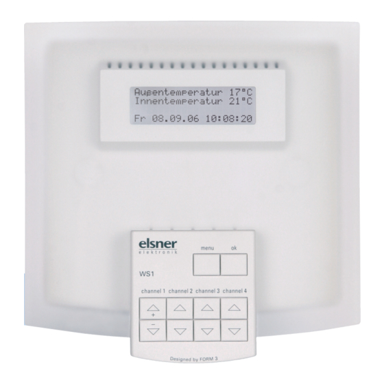
- Page 12 Bedienung Ausgangsstellung mit Wetterdaten-Anzeige In der Ausgangsstellung zeigt die Steuerung die aktuellen Wetterdaten im Display an. Die einzelnen Anzeige-Seiten werden in der Voreinstellung auto- matisch nacheinander angezeigt: • Außentemperatur und Innentemperatur • Helligkeit, Sonnenhöhe und Sonnenwinkel • „Alle Kanäle sind im Automatikbetrieb“ oder die Nummern der Ausgangskanäle die im manuellen Modus sind •...
- Page 13 • „Alarm! Fenster zu!“ Erscheint anstelle von Datum und Uhrzeit, wenn ein angeschlossener Bewegungssensor aktiviert wurde. Wird innerhalb der nächsten 5 Minuten kein neues Signal vom Bewegungsmelder empfangen, verschwindet die Anzeige und die Steuerung schaltet wieder in den normalen Automatik- Modus.
- Page 14 Die WS1 ist stets mit Tasten für vier Kanäle ausgestattet. Je nach Modell sind davon nur die Tasten für Kanal 1 (WS1-1) oder für Kanal 1 und 2 (WS1-2) oder für Kanal 1, 2 und 3 (WS1-3) oder aber alle Tasten (WS1-4) funktionstüchtig! Tasten Menü...
- Page 15 Einstellen der Automatik Die Einstellmenüs für den Automatikbetrieb erreichen Sie aus der Ausgangs- stellung der Steuerung durch Betätigen der Taste menu. In der Ausgangs- stellung befindet sich die Steuerung immer dann, wenn Wetterdaten angezeigt werden. Um die Funktionsgruppen für den Automatikbetrieb einstellen zu können, muss die Grundkonfiguration bereits erfolgt sein (s.
- Page 16 • Stellen Sie nun mit den Tasten + und - Fenster x öffnen ab die Innentemperatur ein, ab der das Innentemperatur größer 25°C gewählte Fenster öffnen soll. Tasten: menu + ok - Bestätigen Sie Ihre Eingabe mit ok. • Stellen Sie die Windgeschwindigkeit, Fenster x schließen ab der das Fenster geschlossen werden ab Windgeschwindig-...
- Page 17 Soll die Markise nicht auf Sonne reagieren, halten Sie die Taste + oder – so lange gedrückt, bis anstelle der Kiloluxangabe „Sensor aus“ im Display erscheint. Bestätigen Sie Ihre Eingabe mit ok. Damit die Automatik reagiert, muss der von Ihnen eingestellte Wert für die Dauer der eingestellten Verzögerungszeiten über- bzw.
- Page 18 Sperrtemperaturen für Markisen Hinweis: Dieser Menüpunkt erscheint nur, wenn in der Grundeinstellung wenigstens ein Kanal als Markise konfiguriert wurde (siehe Kapitel „Grundein- stellung der angeschlossenen Komponenten“, S. 44). • Wählen Sie nach Betätigen der Taste menu mit den Tasten + oder – das Menü...
- Page 19 • Wählen Sie nach Betätigen der Taste menu mit den Tasten + oder - die Jalousie, für die Sie Einstellungen vornehmen wollen. Im Display erscheint: „Automatik einstellen Jalousie x?“ Bestätigen Sie mit ok. • Stellen Sie nun mit den Tasten + und - Jalousie x schließen bei Sonne die Sonnenintensivität ein, ab...
- Page 20 • Stellen Sie nun die Dämmerungsschaltung Jalousie x immer bei ein. Nacht schließen? Nicht schließen Wählen Sie mit den Tasten + oder - ob Tasten: menu + ok - die Jalousie bei Nacht automatisch ge- schlossen werden soll (Dämmerungsschaltung). Bestätigen Sie mit ok. Unabhängig von der Aktivierung der Jalousie x aus - Dämmerungsschaltung kann im nächsten...
- Page 21 • Bei Lammellenjalousien die mit ge- Bitte Lamellen von schlossenen Lamellen ausfahren, können Jalousie x mit Taste + in Position fahren Sie den Winkel für die Reversierung ein- Laufzeit 0 stellen. Bringen Sie die Lamellen mit der Taste + in die gewünschte Stellung. Die Reversierzeit können Sie im Display in der untersten Zeile ablesen.
- Page 22 Beachten Sie, dass bei Nacht- und Zeitraumschließen der Frostschutz (die außentemperatur-geregelte Fahrsperre) nicht aktiviert ist! Antriebe und Jalousie können Schaden nehmen, wenn eine festgefrorene Außenjalousie gefahren wird! Sind alle Einstellungen vorgenommen, wird der Menüpunkt „Sperrtemperatur für Jalousien“ automatisch verlassen und Sie können weitere Menüpunkte an- wählen oder durch Drücken von menu in die Ausgangsstellung mit Wetterdaten- Anzeige zurückkehren.
- Page 23 wurde. Im Display erscheint anstelle der Anzeige von Datum und Uhrzeit die Meldung: „Alarm! Fenster zu!“. Wird innerhalb der nächsten 5 Minuten kein neues Alarmsignal empfangen, wird der normale Automatikbetrieb wieder aufgenommen. Hinweis: Dieser Menüpunkt erscheint nur, wenn in der Grundeinstellung der Bewegungsmelder aktiviert wurde (siehe Kapitel „Grundeinstellung des Bewegungsmelders“, S.
- Page 24 Stufen deklariert sind, vollständig geschlossen, um die Ausgangsposition („Fenster geschlossen“) festzulegen. Wurde einer der Ausgangskanäle 1 bis 4 manuell bedient, kann durch gleich- zeitiges Drücken der Pfeiltasten für „Auf“ und „Ab“ am entsprechenden Kanal die Automatikfunktion wieder aktiviert werden. Soll die ganze Steuerung, das Multifunktionsrelais oder ein WGBL nach einer manuellen Bedienung in die Automatik zurückgenommen werden, gehen Sie vor wie folgt: •...
- Page 25 • Wählen Sie nach Betätigen der Taste menu mit den Tasten + oder - das Menü „Heizung einstellen oder manuell bedienen“ und bestätigen Sie mit • Im Display erscheint: Möchten Sie die Heizung manuell bedienen? Nach Betätigen der Taste ok kann die Ja = ok Nein = menu Heizung mit der Taste + ein- und ausge-...
- Page 26 • Drücken Sie bei der Abfrage, ob Sie die Kühlung manuell bedienen möchten, die Taste menu, können Sie die Werte für den Automatikbetrieb einstellen. • Sie können mit den Tasten + und - die Kühlung ein ab Innentemperatur Innentemperatur einstellen, die über- größer 30°C schritten werden muss um die Kühlung Tasten: menu + ok -...
- Page 27 Lüfter an Lüftermodul WGBL: • Im Display erscheint: Möchten Sie Lüfter WGBL x manuell bedienen? Bestätigen Sie 2x mit ok, kann der Ja = ok Nein = menu angewählte Lüfter mit + und - manuell gesteuert werden. • Wählen Sie „Nein“ (menu) um die Automatikeinstellungen für diesen Lüfter vorzunehmen.
- Page 28 • Nun können Sie die Parameter für den WL305/610 Nr. x Wärmegewinn mittels Umluft-Modus einstellen. Die erhitzte Luft Umluft aktivieren? im Dachbereich kann zum Wärmegewinn Ja = ok Nein = menu genutzt werden. Durch Umwälzung kann so Heizenergie gespart werden. Wählen Sie „Nein“...
- Page 29 • Sommerschaltung (Zuluft geschlossen wenn Außentemperatur höher als Innentemperatur) • Zeitraum für Zwangslüftung Daikin Funk-Klimagerät: • Im Display erscheint: Möchten Sie Daikin x manuell bedienen? Bestätigen Sie 2x mit ok, kann das Ja = ok Nein = menu angewählte Klimagerät mit + und - manuell abgeschaltet oder auf Automatik gestellt werden.
- Page 30 Bei einsetzendem Regen kann je nach Regenmenge und Außentemperatur eine gewisse Zeit vergehen, bis von der Wetterstation Regen erkannt wird. Weiterhin muss für elektrisch betätigte Fenster oder Schiebedächer eine Schließzeit ein- kalkuliert werden. Feuchtigkeitsempfindliche Gegenstände sollten daher nicht in einen Bereich gestellt werden, in dem Sie durch eindringende Feuchtigkeit be- schädigt werden könnten.
- Page 31 Die Steuerung darf nur als ortsfeste Installation betrieben werden, das heißt nur in eingebautem Zustand und nach Abschluss aller Installations- und Inbetrieb- nahmearbeiten und nur im dafür vorgesehenen Umfeld. Für Änderungen der Normen und Standards nach Erscheinen der Bedienungsan- leitung ist Elsner Elektronik nicht haftbar.
- Page 32 Installation der Wetterstation Aufbau der Platine Steckplatz für Anschluss der Steuerung 1: +24 V DC 2: GND 3: Daten Steckplatz für Kabelverbindung zum Niederschlagssensor im Gehäusedeckel Kontroll-LED DCF77-Empfang Stellschraube DCF77-Antenne...
- Page 33 Standort Wählen Sie eine Montageposition am Gebäude, wo Wind, Regen und Sonne un- gehindert von den Sensoren erfasst werden können. Es dürfen keine Konstruk- tionsteile über der Wetterstation angebracht sein, von denen noch Wasser auf den Niederschlagssensor tropfen kann, nachdem es bereits aufgehört hat zu regen oder zu schneien.
- Page 34 Mast, Steg nach unten. Als ergänzendes, optionales Zubehör ist ein Gelenk-Ausleger für die flexible Wand-, Mast- oder Balkenmontage der Wetterstation bei Elsner Elektronik erhältlich. Beispiele für den Einsatz des Gelenk-Auslegers: Bsp.1: Durch den Gelenk-Ausleger schaut die Wetterstation unter dem Dachvorsprung hervor.
- Page 35 Bsp. 2: Montage an einem Mast mit Schneckengewinde-Schellen Ansicht der Rückwand und Bohrplan Bemaßung Gehäuserückseite mit Halter, technisch bedingte Abweichungen möglich Bohrplan...
- Page 36 Vorbereitung der Wetterstation Der Deckel der Wetterstation mit dem Regensensor ist am unteren Rand rechts und links eingerastet (siehe Abb.). Nehmen Sie den Deckel von der Wetterstation ab. Gehen sie sorgfältig vor, um die Kabelverbindung zwischen der Platine im Unterteil und dem Regensensor im Deckel nicht abzureißen (Kabel mit Stecker). Führen Sie das Kabel für Spannungsversorgung und Busanschluss durch die Gummidichtung an der Unterseite der Wetterstation und schließen Spannung und Bus an die dafür vorgesehenen Klemmen an.
- Page 37 Prüfen Sie ob Deckel und Unterteil richtig verrastet sind! Die Abbildung zeigt die geschlossene Wetterstation von unten. Schieben Sie das Gehäuse von oben in den montierten Halter. Die Zapfen des Halters müssen dabei in den Schienen des Gehäuses einrasten. Zum Abnehmen lässt sich die Wetterstation nach oben gegen den Widerstand der Rasten wieder aus dem Halter herausziehen.
- Page 38 Gehäuseaufbau und Anschlussübersicht Feinsicherung T6,3 A Wetterstation, WG-Bus, Handtaster und Bewegungsmelder Kanal 1 Netzanschluss 230 Volt (L/N/PE) Kanal 2 (ab Modell WS1-2) Kanal 3 (ab Modell WS1-3) Kanal 4 (ab Modell WS1-4) Dauerspannung 230 Volt Multifunktionsrelais für Alarm, Heizung oder Kühlung (1 Schließer potenzialfrei)
- Page 39 Ausgang darf mit max. 400 Watt belastet werden. Die Gesamtanschlussleistung darf jedoch ca. 1,6 KW nicht überschreiten. Die Ausgangsspannung beträgt 230 V AC. Standort Direkte Sonnenbestrahlung sollte vermieden werden, da dadurch die Messung der Innentemperatur verfälscht wird. Der Sensor hierfür ist im Bereich des Tastenfeldes eingebaut.
- Page 40 Explosionszeichnung des Gehäuses Um das Gehäuse zu öffnen gehen Sie wie in der Abbildung zu erkennen vor. Die Kunststoffabdeckungen für die Befestigungsschrauben der Frontplatte werden bei der Endmontage fest in die Fräsungen gepresst. Dadurch ist das spätere Entfernen nur schwer möglich und die Abdeckungen werden bei der Demontage beschädigt.
- Page 41 Daten. Anschluss von Elsner Funk-Lüftungsgeräten Um Funk-Lüftungsgeräte an der Steuerung WS1 betreiben zu können, muss das Funkmodul RF868 installiert sein (wird mit den Lüftern geliefert). Der Anschluss des Funkmoduls erfolgt an den Klemmen „WG-Bus“. Bitte beachten Sie die den Lüftern und dem Funkmodul RF868 beiliegenden Installationshinweise.
- Page 42 Der Anschluss des WGBL an den WG-Bus erfolgt mit zweipaarigem Telefon- kabel. Die Zuleitung darf höchstens 100 m lang sein. Beachten Sie bitte auch die dem Lüftermodul beiliegenden Installationshinweise. Bewegungsmelder und Alarmausgang An die Anschlussklemmen + / - / S (Bewegungsmelder) können zwei Systemsen- soren der Fa.
- Page 43 wird also erst beim Neustart der Steuerung angezeigt, nachdem die Grund- konfiguration mit Einlernen der Funkteilnehmer erfolgt ist). • Dann erfolgt die Suche nach einem WGTH (Innenraumsensor). Angezeigt wird „installiert“ bzw. „nicht installiert“. • Alle vorhandenen Sensoren werden sodann intern überprüft. Angezeigt wird „ok“...
- Page 44 Für den Fall, dass die angezeigten Temperatur- und Luftfeuchtigkeitswerte an der Zentraleinheit nicht repräsentativ sind für den Raumdurchschnitt (z. B. wenn die Steuerung oft direkte Sonne hat oder an einer sehr kühlen Stelle im Raum montiert ist), können Sie den Anzeigewert der Sensoren anpassen. (siehe Kapitel „Sensoren Justieren“, S.
- Page 45 Grundeinstellung Grundeinstellung der angeschlossenen Komponenten Fenster, Markisen und Jalousien werden auf verschiedene Art gesteuert. So werden zum Beispiel Fenster in Abhängigkeit von der Temperatur und Luft- feuchtigkeit, Jalousien jedoch in Abhängigkeit von Licht oder Uhrzeit geöffnet und geschlossen. Falsche Grundeinstellungen können darum zu erheblichen Schäden führen, wenn z.
- Page 46 Grundeinstellung von Fenstern Wählen Sie bei der Grundeinstellung des Kanals „Fenster“ und bestätigen Sie mit ok. • Sie können wählen, ob dieses Fenster Soll Fenster x bei Regen automatisch bei Regen geschlossen werden soll oder schließen? nicht. Verändern Sie die Einstellung mit + Tasten: + ok - oder –...
- Page 47 • Nach Bestätigen mit ok erfolgt die Drehrichtung von Motor an Fenster x Drehrichtungsprüfung. überprüfen? Nein Tasten: + ok - Wenn Sie diese Abfrage mit Nein abbrechen, können Sie wie beschrieben die Grundeinstellung des nächsten Kanals vornehmen. • Bei Bestätigung mit Ja erscheint im Display Achtung! Regen/Wind- Alarm während Dreh- die Warnung: „Achtung!! Während Dreh-...
- Page 48 • Es folgt die Abfrage der Markisenrichtung. Rollt das Tuch von Markise x von oben Ist ihre Markise so montiert, dass das Tuch nach unten aus? Ja von unten nach oben ausrollt um zu be- Tasten: + ok - schatten, wird die Zuordnung der Taster des Bedienfelds Ihrer Steuerung geändert, damit die Pfeilrichtung mit der Laufrichtung der Markise übereinstimmt.
- Page 49 Mit den Tasten + und – wählen Sie, Der ext. Handtaster ist für Markise x welchen Kanal Sie mit dem Schalter programmiert bedienen möchten (max. 4 Kanäle zur Tasten: + ok - Auswahl bei WS1-4). Bestätigen Sie Ihre Auswahl mit der Taste ok.
- Page 50 Grundeinstellung des Bewegungsmelders Nach der Zuordnung des Handtasters erfolgt die Aktivierung des Alarmeingangs. Geben Sie hier an, ob Sie einen Bewegungsmelder oder sonstigen Alarmkontakt angeschlossen haben. • Wählen Sie mit + und – und bestätigen Ist ein Alarmkontakt oder Bewegungsmelder Sie mit ok.
- Page 51 • Sie werden gefragt: „Soll (Gerät und 8-stellige Seriennummer) gelöscht werden?“ Wählen Sie mit + oder – „Ja“ oder „Nein“ an und bestätigen Sie mit ok. Sind mehrere Funkteilnehmer eingelernt worden, so beantworten Sie die Abfrage bei allen wie gewünscht. Nach der Bestätigung Ihrer Auswahl erscheint kurz der Text „MC-Reset“...
- Page 52 • Die Temperatursensoren können in gleicher Weise justiert werden. Bestätigen Sie Ihre Einstellungen mit ok. Mit der Taste menu gelangen Sie zurück in die Ausgangsstellung der Steuerung. Displaykontrast einstellen • Halten Sie in der Ausgangsstellung der Steuerung die Taste ok gedrückt und drücken Sie zusätzlich für 2 Sekunden die Taste menu.
- Page 53 Display wird durch das Laden der Liefereinstellungen auf „Deutsch“ eingestellt. Sollten Sie eine der Funktionen benötigen, nehmen Sie daher bitte mit Ihrem Händler oder direkt mit Elsner Elektronik Kontakt auf. Auch der Zugangscode (siehe nächstes Kapitel) kann gelöscht und die Steuerung so notfalls entsperrt werden (z.
- Page 54 Mit der Taste menu gelangen Sie zurück in die Ausgangsstellung der Steuerung. Zugangscode Der Einstellbereich für die Automatik der WS1 kann über einen Zahlencode gegen unbefugtes Verstellen geschützt werden. Ausgeliefert wird die Steuerung mit ungeschütztem Einstellbereich, die Codenummer ist dann 0000. Wird im Folgenden eine von 0000 abweichende Codenummer eingegeben, wird vor jedem Aufrufen der Einstellmenüs der Zahlencode abgefragt.
- Page 55 Wählen Sie mit den Tasten + und - den Menüpunkt „Kundendienstdaten ablesen“. Bestätigen Sie mit ok. • Anhand der angezeigten Werte können WS1-X V X.X Drehrichtung: 0 0 0 0 durchgeführte Drehrichtungsänderungen Tastentausch: 0 0 0 0 oder Tastentausch zurückverfolgt werden.
- Page 56 Wählen Sie mit den Tasten + und - den Menüpunkt „Landessprache im Display ändern“. Bestätigen Sie mit ok. • Bitte die gewünschte Wählen Sie mit den Tasten + und – aus: Sprache auswählen: Deutsch – DEU, Französisch – FR, Englisch – UK. Tasten: menu + ok - Bestätigen Sie Ihre Eingabe mit ok.
- Page 57 Regen- und Windalarm unterdrücken Bei der Inbetriebnahme müssen Antriebe auch bei Regen oder Wind gefahren werden können. Hierzu können die Alarmmeldungen für 10 Minuten unterdrückt und so auch Schiebedächer bei Regen gefahren werden. Zum Starten des Inbe- triebnahmemodus gehen Sie bitte wie folgt vor: •...
- Page 58 Uhr neu gestellt werden. Bei Funkuhrempfang erfolgt dies nach ca. 10 Minuten automatisch. Sollte kein Funkuhrempfang möglich sein, muss die Uhr manuell gestellt werden. Werkseinstellungen Bei Auslieferung der Wintergartensteuerung WS1 sind folgende Vorein- stellungen gespeichert: Grundeinstellung: • Kanal 1 ist Markise 1 •...
- Page 59 Markisen: • Beschattung ab Sonnenintensität > 40 Kilolux (alle Richtungen) • Sperren bis Innentemperatur > 18°C • Sperren bis Außentemperatur > 5°C • Windalarm bei Wind > 4 m/s Jalousien: • Beschattung ab Sonnenintensität > 40 Kilolux (alle Richtungen) • Sperren bis Innentemperatur >...
- Page 60 Funk-Zuluftgeräte WFL: • Lüften ab Luftfeuchtigkeit > 80% • Lüften ab Innentemperatur > 28°C • Winterschaltung ab Außentemperatur < 1° • Sommerschaltung deaktiviert Daikin Klimageräte: • Kühlen ab Innentemperatur > 28°C (Kühlbetrieb im Automatikmodus) • Heizen ab Innentemperatur < 1°C (Heizbetrieb im Automatikmodus) •...
- Page 61 Funkmodul von Elsner Elektronik, ermöglicht die drahtlose Kommunikation von Steuerung und Elsner Lüftern/Daikin Klimageräten WGBL: Lüftermodul von Elsner Elektronik, ermöglicht den Anschluss von Zu- und Abluftgeräten anderer Hersteller an die Steuerung WGTH: Innenraumsensor von Elsner Elektronik mit Thermometer und Hygrometer...
- Page 62 Internes Hygrometer Messbereich 1…99% rF Auflösung 1% rF Internes Thermometer Messbereich 0…+50°C Zur Beurteilung des Produkts hinsichtlich elektromagnetischer Verträglichkeit wurden folgende Normen herangezogen (Störaussendung/Störfestigkeit): • EN 60730-1:2000-11 + A11:2002 Das Produkt wurde von einem akkreditierten EMV-Labor entsprechend den oben genannten Normen überprüft. Wetterstation Gehäuse Kunststoff...
- Page 63 Anschlusspläne...
- Page 66 Persönliche Einstellungsdaten der Automatik Kanäle („channel“) 1-4 (je nach Modell) Kanal 1 Kanal 2 Kanal 3 Kanal 4 Name/Funktion des Kanals Luftfeuchtigkeit (%) Innentemperatur (°C) Außentemperatur (°C) Helligkeit Winkel (Sonne) Positionierung und Reversierung? Windgeschwindigkeit (m/s) Bei Nacht schließen? Schließen im Zeitraum Sperrtemperaturen für alle Sperrtemperaturen für alle Verzögerungszeit Beschattung...
- Page 67 Heizung/Kühlung/Alarm, Belüftung und Klima Luftfeuchtigkeit (%) – – – Innentemperatur – – Belüftung (°C) Innentemperatur – – Heizung (°C) Außentemperatur für – – – Winterschaltung Sommerschaltung EIN? – – – Stufenausnut- – – – zung Belüftung – – – Zeitraum –...
- Page 70 Herdweg 7 • D-75391 Gechingen • Germany Phone: +49 (0) 70 56/93 97-0 • Fax: +49 (0) 70 56/93 97-20 info@elsner-elektronik.de • www.elsner-elektronik.de WS1 • starting with software version 1.9 • Version: 07 Sep 2009 Errors excepted. Subject to technical alterations.
- Page 71 Description................... 73 Scope of supply ..........................73 Start-Up procedure ..........................73 Connection and control possibilities....................73 Overview on available automatic functions..................74 Overview: Automatic control according to weather data .............. 76 Operation ..................... 77 Starting position with weather data display ...............77 Alarm and error messages .......................
- Page 72 Removal of the glass pane......................104 Exploded view of the housing ......................104 Connection of an external indoor sensor (WGTH) ............... 105 Connection of the output channels ....................105 Connection of Elsner wireless ventilation units................106 Connection of ventilators to WGBL ventilation modules............. 106 Motion detector and alarm output ....................
- Page 73 Technical data ......................124 Control .............................. 124 Weather station..........................125 Connection diagrams ....................126 Personal adjustment data of the automatic system..........129...
- Page 74 Scope of supply The WS1 conservatory control is available in 4 designs with 1, 2, 3 or 4 output channels. Each version’s scope of supply includes the control and the P03 weather station.
- Page 75 The following ambient parameters are measured and displayed: • Outdoor and indoor temperature • Indoor humidity • Illumination (intensity and direction, twilight detection) • Wind speed • Precipitation • Time The following additional options are available: • Connection of up to 8 Elsner wireless ventilation units WL610, WL305 and WFL without accessory unit •...
- Page 76 Automatic functions for awnings: • Indoor awnings, without rain and wind alarm • Outdoor awnings, with rain and wind alarm • Extending the awnings depending on sun intensity and altitude • Not extending the awnings below a selectable outside temperature •...
- Page 77 • Winter set-up: supply air is closed if a selectable outdoor temperature is fallen below Additional functions for wireless ventilation units WL610 or WL305: • Recirculation mode for heat gain • Recirculation mode to avoid condensation water Additional functions for WFL wireless supply air units: •...
- Page 78 Operation Starting position with weather data display In the starting position, the control shows the current weather data on the display. The individual display pages are automatically shown one after the other in the default setting: • Outdoor temperature and indoor temperature •...
- Page 79 The WS1 is always fitted with keys for four channels. Depending on the version, only the keys for channel 1 (WS1-1) or for channel 1 and 2 (WS1-2) or for channel 1, 2 and 3 (WS1-3) or all keys (WS1-4) are fully functional!
- Page 80 Menu and ok keys Keypad for manual operation of channel 1 (alternative function + / -), channel 2, channel 3 and channel 4 By using the arrow keys in the control panel, every output channel may be operated manually. If the desired channel should be blocked as a result of rain or wind alarm, a corresponding message will appear on the display if you press the arrow keys (f.
- Page 81 To be able to adjust the functional groups for automatic operation, the basic configuration must be completed (please also refer to chapter “Basic adjustment of connected components“, p. 109). After pressing the menu key, the individual menu items may be selected by using the + and - keys.
- Page 82 Irrespective of these adjustments, all windows will be closed in case of alarm by the motion detector. Also manually opened windows will be closed in case of rain or wind alarm or alarm by the motion detector! In case of rain alarm, the window groups will be closed whose basic setting was adjusted correspondingly (closing is the default setting;...
- Page 83 • Now the sun direction is requested, Close awning x in case of sunlight which the awning is to provide shade for. from any direction By using + or – please select one of the Keys: menu + ok - following possibilities: “from any direction“, ”from east“, “from south“, “from west“...
- Page 84 The automatic sun system will be disabled until the blocking temperature has been reached (heat gain). • After confirming the indoor blocking temperature with the ok key, you may now adjust the desired outdoor temperatures below which the awnings are not to extend.
- Page 85 continuous retraction and extension of the blind in case of rapidly changing light conditions. In case of need, the lag periods may be changed as described in the chapter “Delay time of the shading” (p. 116). • Now the sun direction is requested, Close blind x which the blind is to provide shade for.
- Page 86 • Now adjust the speed for the wind alarm. Retract blind x if wind speed Use the + and/or – keys and confirm exceeds 4.0m/s with ok. Keys: menu + ok - Irrespective of the other selected settings, the blind will then be retracted in case of wind alarm. Blinds do not react to rain alarm, in order to maintain their shield function, if needed, even in case of bad weather conditions.
- Page 87 Blocking temperatures for blinds Please note: This menu item will only be displayed at least one channel has been configured as “blind” in the basic setting (see chapter “Basic adjustment of the connected components“, p. 109). • After pressing the menu key, use the + or – key to select the menu “Set blocking temperature for blinds“.
- Page 88 In case of reception for the radio-controlled clock, a triangle will appear during second 0 between the day and the date. For example, the following may be displayed: We 06-08-30 08:15:00 If the reception of the DCF77 signal should be disturbed, date and time can be set manually.
- Page 89 • By using the + and – keys, you may now Activate alarm entry adjust the period during which the motion from detector/alarm reception is to be active 00:00 00:00 every day. After changing the hours/minutes, please save your value by pressing the ok key. The cursor (flashing rectangle) will then automatically jump to the next position.
- Page 90 For safety reasons, once a day the reset will be carried out by the control itself. You may choose at what time this function is to take place. • You may adjust the reset time and confirm Switch all channels to automatic mode with the ok key.
- Page 91 • Then enter the room temperature, Night reduction of heating until indoor which should be kept during the period temp. reaches 10°C of night-time reduction. Keys: menu + ok - By pressing the menu key you may return to the automatic mode of the control. Adjustment of the cooling Please note: This menu item is only displayed if the multifunctional relay has been adjusted for the function “cooling”.
- Page 92 • After pressing the menu key, use the + or – keys to select the menu “Set ventilation/air-conditioning or operate manually“. Confirm with ok. • By using + and – you may now select the individual connected ventilator controls, wireless ventilators (WL610, WL305, WFL) and Daikin air- conditioning units.
- Page 93 Wireless roof ventilator (WL610/WL305): • The display shows: Do you want to operate WL305/610 no.x manually? If you confirm twice with ok, the selected Yes = ok No = menu ventilator may be manually controlled with + and -. Choose “deactivated” in order to deactivate the ventilator. In case of extracted air level 1, the ventilation flap is open, the fan, however, is inactive.
- Page 94 Select “Yes” (ok) in the indicated display text and set the following parameters: • U-value of the thermopane glazing of your conservatory (to be requested from your conservatory specialist dealer) • Speed level that is to be used for recirculation. WFL wireless supply air unit: •...
- Page 95 switched off and supply air system as well as windows are closed. After switching off the air-conditioning system, ventilation will remain inactive for the time set in this menu item. • Period of night reduction of heating, and indoor temperature to which reduction is to take place By pressing menu several times, you may return to the automatic mode of the control.
- Page 96 Safety notes on the automatic and alarm functions Please note: The values that you set for the output channels, ventilators and for the multifunctional relay will only take effect in the automatic mode. Automatic operation is carried out in the starting position of the control, i.e. if weather data are displayed.
- Page 97 The control must only be operated as stationary system, i.e. only in a fitted state and after completion of all installation and start-up works, and only in the environment intended for this purpose. Elsner Elektronik does not assume any liability for changes in standards after publication of this instruction manual.
- Page 98 Installation of the weather station PCB layout Socket for connecting the control unit 1: +24 V DC 2: GND 3: Data Socket for connecting cables to rain sensor in housing cover DCF77 reception control LED DCF77 antenna set screw...
- Page 99 Position Choose an installation position in the building where wind, rain and sun can be measured unhindered by the sensors. The weather station must not be installed underneath any structural parts from which water can still drip onto the rain sensor after it has stopped raining or snowing.
- Page 100 When pole mounting: curved side on pole, collar downward. An additional, optional accessory available from Elsner Elektronik is an articulated arm for flexible wall, pole or beam mounting of the weather station. Example uses of the hinge arm mounting: Ex.1: With the hinge arm mounting, the...
- Page 101 Ex. 2: Fitting to a pole with worm drive hose clips. View of rear side and drill hole plan Dimensions of rear side of housing with bracket. Subject to change for technical enhancement Drill hole plan...
- Page 102 Preparing the weather station The weather station cover with the rain sensor snaps in on the left and right along the bottom edge (see Fig.). Remove the weather station cover. Proceed carefully, so as not to pull off the wire connecting the PCB in the bottom part with the rain sensor in the cover (wire with push-connector).
- Page 103 Make sure the cover and bottom part are properly snapped together! This picture is looking at the closed weather station from underneath. Push the housing from above into the fastened mount. The bumps on the mount must snap into the rails in the housing. To remove it, the weather station can be simply pulled upwards out of the mount, against the resistance of the fastening.
- Page 104 Microfuse T6,3A Weather station, WG bus, manual key and motion detector Channel 1 Mains supply 230 volt (L/N/PE) Channel 2 (starting from version WS1-2) Channel 3 (starting from version WS1-3) Channel 4 (starting from version WS1-4) Constant voltage 230 Volt...
- Page 105 Position Direct insolation should be avoided, since this will falsify the measurement of indoor temperature. The sensor for measuring the indoor temperature is fitted in the area of the keypad. For the same reason, the control should not be fitted above a heater.
- Page 106 In case of parallel connection of motors, please observe whether a group control relay has been prescribed by the motor manufacturer. Group control relays can be purchased from Elsner Elektronik or from the motor manufacturer. Especially different blind and awning drives may usually only be operated with a group control relay at one output channel.
- Page 107 Connection of Elsner wireless ventilation units In order to be able to operate ventilation units at the WS1 control, the RF868 radio module must be installed (is supplied with the ventilators). The radio module is connected to the “WG bus“ terminals. Please observe the installation notes enclosed with the ventilators and the RF868 radio module.
- Page 108 Commissioning If a device is brought from a cold to a warm area, condensation can form. Before starting the device up, please ensure there is no moisture inside it (if necessary leave to dry). After wiring the system and checking all connection, please proceed as follows: •...
- Page 109 Inspection of the rain sensor Moisten one or several of the golden sensor surfaces in the cover of the weather station. The display will indicate “Rain” on the display page with humidity and wind. Please note that after drying of the sensor the rain indication will continue to be displayed for another 5 minutes.
- Page 110 Basic adjustment Basic adjustment of the connected components Windows, awnings and blinds are controlled differently. For example, windows are opened and closed depending on temperature and humidity, and blinds are opened and closed depending on the light or time. Improper basic settings may therefore cause considerable damages, if f.
- Page 111 Basic adjustment of windows Select “window” in the basic setting of the channel, and confirm with ok. • Window x to close You may select whether this window is to automatically in be closed in case of rain, or not. Adjust the case of rain? No setting with + or –...
- Page 112 If you interrupt this request with No, you may adjust the basic settings of the next channel as described. • If you confirm with Yes, the display will N.B.! Rain/wind alarm deactivated during show the warning: dir. of rotation test! Key: ok Confirm with the ok key.
- Page 113 shading, the allocation of the keys on the key pad of you control will be changed so that the direction of the arrow corresponds with the direction of travel of the awning. Confirm you configuration with ok. If you have selected “No“...
- Page 114 1 the key (max. 4 channels available with Keys: + ok - WS1-4). Confirm your selection with ok. Basic adjustment of the motion detector After the allocation of the manual key, the alarm input is activated. Please indicate whether you have connected a motion detector or other alarm contacts.
- Page 115 • After the basic adjustment of the motion Is a radio subscriber to be detector, the display will show: tought in? Keys: + ok - • If you select “No“ (press ok), the control will be re-started and the basic adjustments you made will be saved.
- Page 116 Special adjustments Adjustment of sensors This function serves for compensation of different humidity and temperature ranges in the room. If the control with the integrated indoor sensor is installed at a relatively “too cool”, “too hot”, “too moist” or “too dry” place, the displayed humidity or temperature value may be adjusted to the actually prevailing room value in this menu.
- Page 117 Change display mode In this menu item please set whether the different measured values and status messages in automatic mode are to be automatically continuously displayed, or whether you would like to manually leaf through the corresponding display pages with the ok key. •...
- Page 118 “German” by the reset to the default setting. If you require one of the functions, please contact your dealer or Elsner Elektronik. Also the access code (see next chapter) may be deleted, which serves to unblock the control in case of emergency (f.
- Page 119 Use the + and – keys to select the menu item “Read customer service data” Confirm with ok. • With the displayed values, any changes to WS1-X V X.X Dir. of rota.: 0 0 0 0 the rotational direction or changed key- Key change: 0 0 0 0 board layouts may be traced back.
- Page 120 • If radio subscribers are thought in, different information such as serial number, WGBL address, temperature, operating hours, number of flap movements and software version are displayed. With ok you may exit the menu. With the menu key you may return to the starting position of the control. Changing the display language The display may be shown in three different languages.
- Page 121 City Longitude (eastern l.) Latitude (northern l.) Berlin 13° 22’ 52° 31’ Bern 7° 27’ 46° 57’ Bremen 8° 48’ 53° 4’ Düsseldorf 6° 47’ 51° 13’ Dresden 13° 44’ 51° 3’ Erfurt 11° 2’ 50° 58’ Frankfurt 8° 40’ 50°...
- Page 122 In case of reception of radio signal, this will be done automatically after approx. 10 minutes. If no radio signal can be received, the clock must be set manually. Settings on delivery When the WS1 conservatory control is delivered, the following default settings are saved: Basic setting: •...
- Page 123 Awnings: • Shading if sun intensity > 40 kilolux (all directions) • Blocking until indoor temperature > 18°C • Blocking until outdoor temperature > 5°C • Wind alarm with wind > 4 m/s Blinds: • Shading if sun intensity > 40 kilolux (all directions) •...
- Page 124 • Recirculation air for heat gain and for avoidance of condensation water deactivated Wireless supply air units WFL: • Ventilation if humidity > 80% RH • Ventilation if indoor temperature > 28°C • Winter set-up if outdoor temperature < 1°C •...
- Page 125 Elsner ventilation units/Daikin air- conditioning units WGBL: Ventilation module by Elsner Elektronik, enables the connection of supply and extracted air units of other manufacturers to the control WGTH: Indoor sensor by Elsner Elektronik with thermometer and...
- Page 126 Power consumption max. 15 W, Stand-by approx. 8 W Internal hygrometer Measurement 1…99% RH range Resolution 1% RH Internal thermometer Measurement 0…+50°C range The following standards were referenced with regard to evaluating electro- magnetic compatibility of the product (Interference emission/ Interference immunity): •...
- Page 127 Connection diagrams...
- Page 130 Personal adjustment data of the automatic system Channels 1-4 (depending on the version) Channel 1 Channel 2 Channel 3 Channel 4 Name/Function of channel Humidity (%) Indoor temperature (°C) Outdoor temperature (°C) Light intensity Angle (sun) Positioning and reversing? Wind speed (m/s) Close at night? Closing from...
- Page 131 Heating/cooling/alarm, ventilation and air-conditioning Humidity (%) – – – Indoor temperature – – Ventilation (°C) Indoor temperature – – Heating (°C) Outdoor temperature for – – – winter set-up Summer set-up ON? – – – Use of levels for from –...
- Page 134 Herdweg 7 • D-75391 Gechingen • Allemangne Tél.: +49 (0) 70 56/93 97-0 • Fax: +49 (0) 70 56/93 97-20 info@elsner-elektronik.de • www.elsner-elektronik.de WS1 • à partir de la version logicielle 1.9 • Dernière mise à jour: 07/09/2009 Sous réserve d’erreurs. Sous réserve de modifications techniques.
- Page 135 Description..................137 Volume de la livraison........................137 Procédure de mise en marche......................137 Possibilités de raccordement et de commande................137 Aperçu des fonctions automatiques disponibles ................. 138 Aperçu : Commande automatique en fonction des données météorologiques......141 Commande ..................142 Mode initial avec affichage des données météorologiques........142 Messages d’alarme et d’erreur.......................
- Page 136 Raccordement des canaux de sortie ....................171 Raccordement de ventilateurs radio Elsner .................. 172 Raccordement de ventilateurs via les modules de ventilation WGBL........173 Détecteur de mouvement et sortie d’alarme ................173 Mise en service ......................173 Contrôle du détecteur de soleil ...................... 174 Contrôle du détecteur de pluie .......................
- Page 137 Plans de câblage .......................194 Données de réglage personnelles relatives à l’automatique ........197...
- Page 138 Description La commande pour jardin d’hiver WS1 a été développée afin de permettre une commande centralisée des différents éléments techniques installés dans des jardins d’hiver. En termes de raccordement et de réglage, cette commande assure un maximum de flexibilité, ce qui permet une adaptation optimale et individuelle à...
- Page 139 • le chauffage ou le refroidissement peut être connecté au relais multifonction, ou bien ce dernier peut être utilisé en tant que sortie d’alarme Les paramètres environnementaux suivants sont mesurés et affichés : • température extérieure et intérieure • humidité de l’air à l’intérieur •...
- Page 140 les messages d’état relatifs à la commande manuelle et les messages d’erreur sont affichés sur l’écran. Fonctions automatiques pour stores : • stores intérieurs, sans alarme de pluie et de vent • stores extérieurs avec alarme de pluie et de vent •...
- Page 141 Fonctions automatiques pour le refroidissement (attention : la configuration du relais multifonction n’est possible qu’en tant que chauffage ou refroidisse- ment) : • activer le refroidissement à partir d’une température ambiante qui peut être choisie librement Fonctions automatiques pour la ventilation : •...
- Page 142 Aperçu : Commande automatique en fonction des données météorologiques Fenêtre/ Store Persienne Chauffage/ Ventilation toit refroi- coulissant dissement – Fonction de Fonction de – Mode Température verrouillage verrouillage d’hiver/d’été extérieure (priorité en (priorité en fonction de la fonction de la luminosité) luminosité) Température...
- Page 143 Commande Mode initial avec affichage des données météorologiques En mode initial, la commande affiche les données météorologiques sur l’écran. Conformément au préréglage, les différentes pages de l’affichage sont affichées automatiquement l’une après l’autre : • température extérieure et ambiante • luminosité, hauteur et angle du soleil •...
- Page 144 La WS1 est toujours équipée de touches pour quatre canaux. En fonction du modèle, uniquement les touches pour le canal 1 (WS1-1) ou pour le canal 1 et 2 (WS1-2) ou pour le canal 1, 2 et 3 (WS1-3) ou bien toutes les touches (WS1-4) sont prêtes à fonctionner !
- Page 145 Touches menu et ok Touches pour la commande manuelle du canal 1 (fonction alternative + / -), canal 2, canal 3 et canal 4 Les touches flèches sur le panneau de commande permettent de commander manuellement chacun des canaux de sortie. Au cas où le canal désiré serait bloqué...
- Page 146 commande se trouve toujours en mode initial lorsque les données météorolo- giques sont affichées. Afin de pouvoir régler les groupes de fonctions pour le mode automatique, la configuration de base doit déjà avoir été effectuée (voir aussi le chapitre « Réglage de base des composants raccordés », p. 176). Après avoir appuyé...
- Page 147 • Maintenant, servez-vous des touches + et - Ouvrir fenêtre x à.p.d. t° ambiante pour régler la température ambiante à supérieure à 25°C partir de laquelle la fenêtre sélectionnée Touches: menu + ok - doit être ouverte. Confirmez votre entrée par ok. •...
- Page 148 • Maintenant, servez-vous des touches + et - Fermer store x pour définir l’intensité du soleil à partir de si soleil supérieur à 40 klx laquelle le store doit être fermé. Touches: menu + ok - Si vous souhaitez que le store ne réagisse pas au soleil, gardez enfoncée la touche + ou –...
- Page 149 pluie ou de vent indépendamment des valeurs choisies. En cas d’un réglage de base sur « store intérieur », l’alarme de pluie et de vent est désactivée. Les températures de blocage non pas atteintes priment sur l’intensité du soleil (cf. chapitre «...
- Page 150 Réglage des persiennes Ici, vous réglez l’intensité du soleil et les points cardinaux, respectivement l’angle, à partir desquels vous souhaitez que la persienne assure l’ombrage. En plus, vous y réglez la fermeture crépusculaire et la fermeture temporisée, ainsi que la vitesse du vent à laquelle la persienne doit être entrée. En plus, vous pouvez ajuster l’automatique de positionnement et d’inversion du sens, c’est-à- dire définir si les lamelles sont inclinées pour permettre la pénétration optimale de la lumière et/ou si la persienne n’est fermée qu’en partie.
- Page 151 L’angle du soleil (azimut) est indiqué en degrés (°). Nord équivaut à 0°, Est à 90°, Sud à 180° et Ouest à 270°. L’ombrage « dir. Est » signifie une couverture entre 0° et 180°, « dir. Sud » entre 90° et 270° et «...
- Page 152 Les persiennes ne réagissent pas à l’alarme de pluie afin de pouvoir assurer la protection contre les regards indiscrets également en cas de mauvais temps – si besoin est. • Ensuite, vous pouvez régler l’automatique Régler inversion d’inversion du sens. A cet effet, appuyez autom.
- Page 153 • Après avoir appuyé sur la touche menu, servez-vous des touches + ou - pour sélectionner le menu « Régler temp. blocage des persiennes ». Confirmez par ok. • Maintenant, vous pouvez vous servir des Bloquer persiennes jusqu'à t° ambiante touches + et - pour régler la température supérieur à...
- Page 154 Si l’horloge radio reçoit des signaux, un triangle apparaît entre le jour et la date pendant la seconde 0. L’affichage est p. ex. le suivant : Me 30/08/06 08:15:00 Au cas où la réception du signal DCF77 serait perturbée, la date et l’heure peuvent être réglées manuellement.
- Page 155 • Après avoir appuyé sur la touche menu, servez-vous des touches + ou - pour sélectionner le menu « Régler durée de surveillance du détecteur de mouvement ». Confirmez par ok. • Maintenant, les touches + et - permettent Activer l'entrée d'alarme de régler le laps de temps pendant lequel à...
- Page 156 • Après avoir appuyé sur la touche menu, servez-vous des touches + ou - pour sélectionner le menu « Remettre commande en mode autom./régler l’heure de réinit. ». Confirmez par ok. • En appuyant sur ok, vous pouvez Réinitialiser mode maintenant réinitialiser le mode auto- autom.
- Page 157 • Affichages sur l’écran : Voulez-vous command. le chauffage manuellement? Après avoir appuyé sur la touche ok, le Oui = ok Non = menu chauffage peut être allumé et éteint via la touche +. L’état est affiché. • Si vous appuyez sur la touche menu pour répondre à la question de savoir si vous souhaitez commander le chauffage manuellement, vous pouvez régler les valeurs relatives au mode automatique : •...
- Page 158 • Si vous appuyez sur la touche menu pour répondre à la question de savoir si vous souhaitez commander le refroidissement manuellement, vous pouvez régler les valeurs relatives au mode automatique : • A l’aide des touches + et -, vous pouvez Refroidissement régler la valeur que la température activé...
- Page 159 Ventilateur sur le module de ventilation WGBL : • Affichage sur l’écran : Voulez-vous com- mander manuellement Si vous confirmez 2 fois en appuyant sur WGBL ventilateur x? Oui = ok Non = menu ok, le ventilateur sélectionné peut être commandé...
- Page 160 peut être utilisé pour chauffer l’intérieur. Grâce à la recirculation, la consommation d’énergie de chauffage peut être réduite. Sélectionnez « Non » (menu) pour désactiver cette fonction. Après avoir sélectionné « Oui » (ok), vous pouvez définir les valeurs suivantes : •...
- Page 161 • mode d’été (admission d’air frais fermée si la température extérieure dépasse la température ambiante) • durée de la ventilation forcée Climatiseur radio Daikin : • Voulez-vous com- Affichage sur l’écran : mander manuellement Daikin x? Si vous confirmez ce message en appuyant Oui = ok Non = menu 2 fois sur ok, le climatiseur sélectionné...
- Page 162 dans les menus de réglage, le mode automatique est désactivé. Si, dans le cadre réglage dans les menus, aucune entrée n’est effectuée pendant 2 minutes, la commande retourne automatiquement en mode initial. Lorsqu’il commence à pleuvoir, un certain délai peut passer en fonction du volume de pluie et de la température extérieure avant que la station météorolo- gique ne détecte la pluie.
- Page 163 à-dire exclusivement en état installé, après l’achèvement de tous les travaux d’installation et de mise en service et dans l’environnement prévu à cet effet. Elsner Elektronik décline toute responsabilité pour les modifications des normes et standards qui interviennent après la parution des présentes instructions de...
- Page 164 Installation de la station météorologique Construction de la platine Emplacement pour le raccordement de la commande 1: +24 V CC 2: GND 3: Données Emplacement pour le raccordement de câbles au détecteur de pluie dans le couvercle du boîtier DEL de contrôle réception DCF77 Vis de réglage antenne DCF77...
- Page 165 Emplacement Choisissez une position de montage sur l’édifice où le vent, la pluie et le soleil peuvent être reçus librement par les détecteurs. Aucuns composants de construction ne doivent être montés sur la station météorologique desquels de l’eau peut couler sur le détecteur de pluie après qu’il avait cessé de pleuvoir ou de neiger.
- Page 166 Elsner Elektronik. Exemples d’application du bras articulé : Exemple 1 : le bras articulé permet à la station météorologique...
- Page 167 Exemple 2 : montage sur un pylône à l’aide d’un collier de serrage. Vue de la face arrière et plan de perçage Dimensions face arrière du boîtier avec support, écarts techniques possibles Plan de perçage...
- Page 168 Préparation de la station météorologique Le couvercle de la station météorologique avec détecteur de pluie est encliqueté au bord inférieur à droite et à gauche (voir fig.). Retirez le couvercle de la station météorologique. Procédez avec précaution pour ne pas déchirer le raccordement de câble entre la platine à...
- Page 169 Montage de la station météorologique Fermez le boîtier en mettant le couvercle sur la partie inférieure. Le couvercle doit s’encliqueter à droite et à gauche avec un « clic » audible. Contrôlez si le couvercle et la partie inférieure sont correctement encliquetés. La figure illustre la station météorologique fermée du bas.
- Page 170 Station météorologique, WG-Bus, bouton-poussoir et détecteur de mouvement Canal 1 Branchement secteur 230 volt (L/N/PE) Canal 2 (à partire du modèle WS1-2) Canal 3 (à partire du modèle WS1-3) Canal 4 (à partire du modèle WS1-4) Tension permanente 230 volt Relais multifonction pour l’alarme, le chauffage ou le refroidissement...
- Page 171 L’appareil fonctionne à 230 V de courant alternatif (50 Hz) ; la puissance absorbée dépend du nombre et de la performance des moteurs raccordés. Chaque sortie peut être chargée de 400 watts au maximum. Toutefois, la puissance connectée totale ne doit pas dépasser 1,6 KW. La tension de sortie est de 230 V AC.
- Page 172 Eclaté du boîtier Pour ouvrir le boîtier, procédez comme indiqué dans les images. Lors du montage final, les capuchons en plastique pour les vis de fixation de la plaque avant sont bien enfoncés dans les trous fraisés. Ainsi est-il très difficile de les enlever plus tard et les capuchons sont endommagés en cas de démontage.
- Page 173 En cas de mise en parallèle de moteurs, veuillez vérifier si le fabricant du moteur prescrit l’emploi d’un relais de contrôle de groupe. Les relais de contrôle de groupe sont fournis par Elsner Elektronik ou bien par le fabricant du moteur. Notamment de différents entraînements de persiennes et stores peuvent – le pus souvent –...
- Page 174 Raccordement de ventilateurs via les modules de ventilation WGBL Les modules de ventilation doivent être installés sous crépi dans des salles sèches. En cas de montage sur crépi, des entrées de ligne adéquates doivent être prévues. Le WGBL est raccordé au WG-Bus à l’aide d’un câble de téléphone à...
- Page 175 • Sur l’écran, le modèle, la version logicielle, le byte de calibrage de l’oscillateur (« HEX OSC ») et le numéro de série (« NS ») sont affichés tout d’abord • Un module radio RF868 raccordé est recherché. Le message « ok » ou « ne pas trouvé...
- Page 176 Contrôle du détecteur de vent Si vous soufflez dans le tube de détection sur la face inférieure de la station météorologique, la vitesse respective en mètres par seconde est affichée sur l’écran. A l’instar du message de pluie, l’alarme de vent est également maintenue pendant 5 minutes.
- Page 177 Réglage de base Réglage de base des composants raccordés Les fenêtres, les stores et les persiennes sont commandés tous d’une manière différente. Par exemple, les fenêtres sont ouvertes et fermées en fonction de la température et de l’humidité de l’air, tandis que les persiennes sont abaissées et remontées en fonction de la lumière ou de l’heure.
- Page 178 • Apprentissage de participants radio (ventilateurs Elsner ou climatiseurs Daikin) Réglage de base des fenêtres Lors du réglage de base du canal, sélectionnez « Fenêtre » et confirmez ce choix en appuyant sur ok. • Vous pouvez choisir si cette fenêtre Fermeture automati.
- Page 179 Pas tous les moteurs conviennent au mode progressif ou au mode toit coulissant. A ce sujet, demandez des informations à votre fournisseur de moteurs. • Après la confirmation par ok, le contrôle Vérifier sens de ro- du sens de rotation est effectué. tation du moteur sur fenêtre x? Touches: + ok -...
- Page 180 • Faites votre choix entre un store intérieur Store x monté à ou extérieur. En cas d’un store intérieur, l'int. ou à l'ext.? Store extérieur le vent et la pluie n’ont pas d’influence; Touches: + ok - en ce qui concerne le store extérieur, ce dernier est entré...
- Page 181 Vous passez automatiquement au réglage du prochain canal, respectivement des autres composants raccordés. Réglage de base des ventilateurs sur WGBL Ce point n’est affiché que si vous avez raccordé des WGBL (modules de ventilation)! • Après l’affectation des canaux (voir Réglage de base WGBL ci-dessus) le message suivant est affiché...
- Page 182 (en cas de WS1-4, au maximum 4 canaux à choisir). Veuillez confirmer votre sélection en appuyant sur la touche ok. . Réglage de base du détecteur de mouvement Après l’affectation du bouton-poussoir, l’entrée d’alarme est activée. Veuillez indiquer ici si vous avez branché un détecteur de mouvement ou un autre contact d’alarme.
- Page 183 Si vous sélectionnez « Non » (appuyer sur ok), la commande est redémarrée et vos réglages sont enregistrés. A l’aide des touches + ou -, vous passez à « Oui ». Confirmez par ok. • La question suivante vous est posée : « Supprimer (appareil et numéro de série à...
- Page 184 • Maintenant, ajustez la valeur de l’ hygro- Ajuster hygromètre Val. de mesure:xx% mètre. Le chiffre indiqué derrière Nouv. valeur:xx% « Valeur de mesure » représente l’humidité Touches: + ok - de l’air actuellement mesurée sans correction. Vous pouvez corriger le chiffre indiqué derrière « Nouvelle valeur »...
- Page 185 A l’aide des touches + ou -, définissez le Avance autom. ou man. de l'affichage? passage automatique ou manuel de Automat. l’affichage à la page suivante. Confirmez Touches: + ok - votre entrée en appuyant sur ok. A l’aide de la touche menu, vous retournez au mode initial de la commande. Temporisation du dispositif d’ombrage Ici, vous réglez la temporisation du dispositif d’ombrage.
- Page 186 A l’aide de la touche menu, vous retournez au mode initial de la commande. Code d’accès La zone de réglage pour le mode automatique de la WS1 peut être protégée contre des modifications non-autorisées à l’aide d’un code chiffré. Lors de la livraison, la zone de réglage de la commande n’est pas protégée et le code est...
- Page 187 A l’aide des touches + et - sélectionnez le point de menu « Lecture des données service après-vente ». Confirmez par ok. • Sur la base des valeurs affichées, il est WS1- X V X.X Sense de rota:0 0 0 0 possible de tracer les modifications du Change.touch:0 0 0 0 sens de rotation effectuées ou bien les...
- Page 188 • Si des participants radio sont connectés, de différentes informations telles que le numéro de série, l’adresse WGBL, la température, les heures de service, le nombre de mouvements du clapet et la version logicielle sont affichées. En appuyant sur ok, vous quittez le menu. A l’aide de la touche menu, vous retournez au mode initial de la commande.
- Page 189 • Saisissez le degré de latitude de la même façon et confirmez votre saisie en appuyant sur ok. A l’aide de la touche menu, vous retournez au mode initial de la commande. Ville Degré de longitude Degré de latitude (longitude nord) (latitude nord) Berlin 13°...
- Page 190 10 minutes. Au cas où la réception radio-pilotée ne serait pas possible, l’horloge doit être réglée manuellement. Réglages d’usine Lors de la livraison de la commande pour jardin d’hiver WS1, les préréglages suivants sont enregistrés : Réglage de base : •...
- Page 191 Stores : • Ombrage à partir d’une intensité du soleil > 40 kilolux (toutes les directions) • Bloquer jusqu’à une température ambiante > 18°C • Bloquer jusqu’à une température extérieure > 5°C • Alarme de vent en cas de vent > 4 m/s Persiennes : •...
- Page 192 • Recirculation de l’air pour la génération de chaleur et pour éviter la condensation désactivée Appareils radio à air frais WFL : • Aération à partir d’une humidité de l’air > 80% Hr • Aération à partir d’une température ambiante > 28°C •...
- Page 193 Mètres par seconde, unité de la vitesse du vent Hr : humidité relative de l’air RF868 : Module radio d’Elsner Elektronik, permet la communication sans fil entre la commande et les ventilateurs Elsner / climatiseurs Daikin WGBL : Module de ventilation d’Elsner Elektronik, permet le raccordement à...
- Page 194 Température ambiante Service +5…+50°C, stockage -20…+70°C , eviter la condensation Tension de service 230 V AC, 50 Hz Puissance absorbée 15 W au maximum, état de veille env. 8 W Hygromètre interne Plage de mesure 1…99% d’humidité relative Résolution 1% d’humidité relative Thermomètre interne Plage de mesure 0…+50°C...
- Page 195 Plans de câblage...
- Page 198 Données de réglage personnelles relatives à l’automatique Canaux (« channel ») 1 à 4 (en fonction du modèle) Canal 1 Canal 2 Canal 3 Canal 4 Nom/fonction du canal Humidité de l’air (%) Température ambiante (°C) Température extérieure (°C) Luminosité Angle (soleil) Positionnement et inversion du sens ?
- Page 199 Chauffage/Refroidissement/Alarme, aération et climatisation Humidité de l’air (%) – – – Température ambiante – – Ventilation (°C) Température ambiante – – Chauffage (°C) Température extérieure – – – pour mode d’hiver ACTIVER le mode d’été ? – – – Utilisation des –...
- Page 200 Elsner Elektronik GmbH Steuerungs- und Automatisierungstechnik Herdweg 7 75391 Gechingen Deutschland Tel.: +49 (0) 70 56/93 97-0 Fax: +49 (0) 70 56/93 97-20 info@elsner-elektronik.de http://www.elsner-elektronik.de...