Publicité
Les langues disponibles
Les langues disponibles
Liens rapides
Publicité

Manuels Connexes pour Corghi Artiglio 500


Sommaire des Matières pour Corghi Artiglio 500
- Page 1 Artiglio 500 Code 4-130269A - 11/2016 English Operator’s manual Français Manuel d’utilisation...
- Page 2 CORGHI Dear Purchaser Thank you for purchasing your Corghi Tyre Changer. Your Tyre Changer has been designed to provide years of safe and dependable service, as long as it is used and maintained in accordance with the instructions provided in this manual.
- Page 3 Mounting of Stiff, Low Profile Tyres Reverse Drop Centre Wheels Proper Bead Lubrication for Mounting Protection Accessories Instructions for the Correct Use of Accessories Bead Sealing and Seating Inflation Safety Precautions Lubrication and Removal of Valve Core Bead Sealing and Seating Artiglio 500 User Manual...
- Page 4 Individuals and Dates Trained _____________________________________________________________________ _____________________________________________________________________ _____________________________________________________________________ _____________________________________________________________________ _____________________________________________________________________ _____________________________________________________________________ _____________________________________________________________________ _____________________________________________________________________ _____________________________________________________________________ _____________________________________________________________________ Artiglio 500 User Manual...
- Page 5 5.2 LOADING AND CLAMPING THE WHEEL ...........33 5.3 DEFLATING THE TYRE .................36 5.4 BEAD BREAKING ..................36 5.5 DEMOUNTING ....................40 5.6 MOUNTING ....................48 5.7 EXTRAORDINARY MOUNTING PROCEDURE ..........51 5.8 APPROVED UHP AND RUN FLAT TYRE DEMOUNTING AND MOUNTING PROCEDURE ......................51 Artiglio 500 User Manual...
- Page 6 INFORMATION AND WARNINGS ABOUT HYDRAULIC FLUID . 11. FIREFIGHTING MEANS USABLE ..........65 12. GLOSSARY ..................66 13. ELECTRIC DIAGRAM ..............69 14. GENERAL PNEUMATIC SYSTEM DIAGRAM ......70 TABLE FOR USING CENTRING AND CLAMPING ACCESSORIES ACCORDING TO RIM TYPE ..................72 Artiglio 500 User Manual...
- Page 7 In addition, so we can contact our customers with any necessary safety information, please ask the new owner to complete and return to Corghi the change of ownership form attached to the previous page of this manual. Alternatively, the new owner can send an email to service@corghi.com.
- Page 8 For example, never mount a 16.5” tyre on a 16” rim and vice versa. This is very dangerous. A mismatched tyre and rim could explode, resulting in an accident. Artiglio 500 User Manual...
- Page 9 • Keep hands, feet and other body parts away from moving parts. • Do not use tools other than those supplied with tyre changer. • Use proper tyre lubricate to prevent tyre binding. • Pay attention while moving tyre/rim or lever. Artiglio 500 User Manual...
- Page 10 21. Wear non-slip safety footwear when operating the tyre changer. 22. Wear proper back support and employ a proper lifting technique when placing, moving, lifting or removing wheels from the tyre changer. Artiglio 500 User Manual...
- Page 11 23. This machine may only be used, maintained or repaired by properly trained employees of your company. Repairs should only be performed by qualified personnel. Your CORGHI service representative is the most qualified person. The employer is responsible for determining if an em- ployee is qualified to safely make any repairs to the machine should repair be attempted by users.
- Page 12 TIONS 461933 DECAL, INFLATING PEDAL 461932 DECAL, TURNTABLE ROTA- TION PEDAL 462080 DECAL, ACOUSTIC AND VISU- AL PROTECTION 461930 DECAL, FOOT CRUSHING HAZARD 425211 DECAL, ELECTRIC HAZARD 432740 DECAL, EXPLOSION HAZARD 4-108591 DECAL, CONSOLLE CON- TROLS Artiglio 500 User Manual...
- Page 13 DECAL, MODEL SERIAL NUM- 42015 - Correggio (RE) Italy Mod. ISO9001 QUAL. SYS. CERTIFIED ANNO DI COSTRUZIONE / Code MANUFACTURED X-XXXXXXXX/XX - XX Serial N. bar7psi Port.max XXXXXXXXX 4-121505 DECAL, WARNING. DANGER WARNING DECALS part nr 462081. Crushing Hazard. Artiglio 500 User Manual...
- Page 14 425211A. Risk of electrical shock. part nr 4-104920. Crushing hazard. Only one operator may operate and use the machine. part nr 462778. Safety instructions. part nr 425083. Earth ground terminal. part nr 432740. Explosion hazard. Artiglio 500 User Manual...
- Page 15 Make sure the available pressure and the rendered capacity of the compressed air system are compatible with those required for correct machine operation - see the “Technical Data” section. For correct machine operation, the compressed air supply line must provide a Artiglio 500 User Manual...
- Page 16 • maximum tyre diameter ................1200 mm (47”) • maximum tyre width ............ 15” (from wheel support surface) - Turntable: • rest ..........................flanged • centring ........................on cone • clamping ....................mechanical-manual • drive system................2-speed motor-inverter unit Artiglio 500 User Manual...
- Page 17 Air is stored in a reservoir for operation of inflation jets. 4. Only activate the air inflation jets if the rim securing device is locked in place and the tyre is properly clamped (when possible). Artiglio 500 User Manual...
- Page 18 1.6. PRE-USE CHECKS Before beginning work, carefully check that all components of the machine, especially rub- ber or plastic parts, are in place, in good condition and working properly. If the inspection Artiglio 500 User Manual...
- Page 19 Do not stack other goods on top of the packing or damage may result. Handling To move the packing, insert the tines of a fork-lift truck into the slots on the base of the packing itself (pallet) (Fig.3). Before moving the machine, refer to the HOISTING/ HANDLING section. Artiglio 500 User Manual...
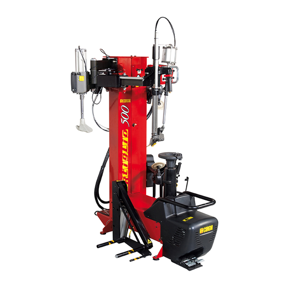
- Page 20 (fig.5): 1. Body with pedal unit and turntable. 2. Column with bead breaking unit and tool arm. 3. Air tank (T.I. version only). 4. Wheel lift. 5. Bead presser (Optional). 6. Accessories box (see Fig. 4). Artiglio 500 User Manual...
- Page 21 Artiglio 500 User Manual...
- Page 22 (A) and nuts (B) (fig.5) (T.I. version only). To remove the machine from the pallet connect to it by means of the lifting bracket 1 provided, as shown in fig. 7. Artiglio 500 User Manual...
- Page 23 Do not install the machine outdoors. It is designed for use in an indoor, sheltered area. Install the tyre changer in the cho- sen work position, complying with the minimum clearances shown in Fig.8. The surface must have a load-carry- ing capacity of at least 1000 kg/m 1200 mm Artiglio 500 User Manual...
- Page 24 (A, fig. 8c) and move the lever to the left (B, fig. 8c). Artiglio 500 User Manual...
- Page 25 fixed part for perfect demounting without having to use the bead-lifting lever* * In a very few cases, a manual “help” accessory supplied as standard may be of use in simplifying de- Artiglio 500 User Manual...
- Page 26 • Width ....................... B = 1000 mm • Width (with wheel lift) ................. B1 = 1290 mm • Max width when fully open ................. B2 = 1580 mm • Height max ...................... H = 2100 mm Artiglio 500 User Manual...
- Page 27 WARNING EXPLOSION HAZARD For technical characteristics, warnings, maintenance and any other information about the air tank (optional), consult the relevant operator and maintenance manual provided with the accessory documentation. Artiglio 500 User Manual...
- Page 28 Artiglio 500 User Manual...
- Page 29 24 Upper bead-breaker arm opening release. 4.4. CONTROLS 4.4.a. OPERATING CONSOLE (Fig. 13) 1 Bead-breaking arm release button 2 Upper bead-breaker up/down control valve 3 Lower bead-breaker up/down control valve 4 Upper bead-breaker disk penetration control valve Artiglio 500 User Manual...
- Page 30 • Pedal in the rest position (stable position): turntable stopped. • Pedal gently pressed downwards (unstable position): slow clockwise rotation. • Pedal pressed entirely downwards (unstable position): fast clockwise rotation. 4.4.d. WHEEL LIFTER CONTROL PEDAL (Fig. 16) 1 Wheel lifting pedal 2 Wheel lowering pedal Artiglio 500 User Manual...
- Page 31 “ORIGINAL ACCESSORIES FOR THE ARTIGLIO A 500 TYRE CHANGER”. 5. BASIC PROCEDURES - USE WARNING CRUSHING HAZARD: Some parts of the machine, such as the head, the bead break- ers and turntable moves during operations. Do not approach moving parts of the machine. Artiglio 500 User Manual...
- Page 32 A - Place the wheel on the lift. B - Lift the wheel by operating the pedal (1). C - Transfer the wheel to the turntable by hand and lower the lift by operating the pedal (2). Artiglio 500 User Manual...
- Page 33 D - When positioning the wheel on the turntable, also take care to align the mobile pin, on the edge of the turntable, in one of the fixing bolt holes in the rim. Artiglio 500 User Manual...
- Page 34 C - By hand, move the centring cone into pos. on the rim by moving the retainers 1. D - Tighten the clamping device by turning the handles 2 clockwise. NOTICE See the section “TABLE FOR USING CENTRING AND CLAMPING ACCESSORIES ACCORDING TO RIM TYPE” in this manual. Artiglio 500 User Manual...
- Page 35 (which is incorporated in the valve, fixed with the belt, glued inside the tyre, etc.) appropriate mount- ing/demounting procedures should be followed (ref. Approved mounting/demounting procedure for runflat and UHP tyres) Artiglio 500 User Manual...
- Page 36 B - Move the disk close to the rim by means of the button and then lever (Fig. 25b). WARNING With this operation, the two arms are moved together. Make sure therefore that the lower arm is in idle position, fully down. Artiglio 500 User Manual...
- Page 37 2-3 mm (Fig. 25c), release the button and lever to stop horizontal movement. Breaking the top bead. A - Preload the bead breaker disc using control (Fig. 26a) (the tyre should be pressed down by about 5 mm). Artiglio 500 User Manual...
- Page 38 (Fig. 27). Move the bead-breaker disk at a distance of 2-3 mm from the rim edge. NOTICE Do not bring horizontally closer because when the upper arm comes closer so does the lower arm. Artiglio 500 User Manual...
- Page 39 C - Complete at least one full turn to achieve bead- breaking. It is best to grease the rim bead during rotation (Fig. 28a). D - Return the bead-breaking unit down (Fig. 28c). With this control, bead-breaker disk penetration is reset. Artiglio 500 User Manual...
- Page 40 D - Press the the handle button to fix the tool position (Fig. 29c). Engaging the top bead A- Maintaining the pressure of the bead breaker disc on the tyre (Fig. 30a), create enough space to allow the demount tool to be rocked. Artiglio 500 User Manual...
- Page 41 D- Move the bead breaker disk upper in not-working position (Fig. 30d). E - For easier bead engagement, it might be very helpful to use the bead breaker disc on the underside of the tyre (Fig. 30e). Artiglio 500 User Manual...
- Page 42 If necessary, use a clamp and/or bead presser for assistance (fig.31b). C - Now, and only now, operate the pedal until the bead is com- pletely demounted (Fig. 31c). Artiglio 500 User Manual...
- Page 43 In this case it is es- sential to restore the ideal condition, with the tyre bead inside the well of the rim. This operation can be assisted with any tool you wish (clamp provided, pliers, bead presser or lever). Artiglio 500 User Manual...
- Page 44 Demounting the bottom bead (Demounting using the tool head) A - Push the bead breaker disc against the bottom bead using control (Fig. 32a). B - Using control , operate the hook and engage the bottom bead of the tyre (Fig. 32a). Artiglio 500 User Manual...
- Page 45 (Fig. 33a). C - Start to rotate the wheel (pedal ) and at the same time raise the disc a little at a time. Rotate until the tyre is com- pletely demount- ed (Fig. 33b). Artiglio 500 User Manual...
- Page 46 B - turn the bead-breaker disk by 180° (Fig. 34b). move the bead- breaker arm from on top to under the wheel (Fig. 34c). D -close the bead-breaker arm again (Fig. 34a) E - extract the lower bead (Fig. 34d). Artiglio 500 User Manual...
- Page 47 Even if the tool does touch the rim as the tyre is engaged, this will not damage the rim in any way. The pressure applied is very low. Artiglio 500 User Manual...
- Page 48 Positioning the tool head (Fig.37) A - Operate control 1 to move the tool head into the working position. The tool is already in the correct position for mounting the tyre, unless the type of rim has been changed. Artiglio 500 User Manual...
- Page 49 Take care that the tyre does not slip underneath the tool. Positioning the bead breaker disc (fig.40) A - Lower the bead breaker disc until it is level with the well of the rim and make enough room for the clamp to be inserted. Artiglio 500 User Manual...
- Page 50 C - Apply more pressure to the tyre and move the tool head to the rest position (Fig. 41a). D - Start rotation again until the clamp is close to the bead breaker disc and re- Artiglio 500 User Manual...
- Page 51 fig.41a onward remain unchanged. 5.8. APPROVED UHP AND RUN FLAT TYRE DEMOUNTING AND MOUNTING PROCEDURE For this type of tyre please refer to the instructions in the manual prepared by WDK (German Tyre Industry Association). Artiglio 500 User Manual...
- Page 52 Remove the valve stem core if not already done. Connect the inflation hose to the valve stem. Step down partially on the pedal to inflate the tyre and seal beads with the inflation hose. Frequently stop to check bead seating pressure on the gauge. Artiglio 500 User Manual...
- Page 53 1. Make sure the wheel on which the tyre is fitted is securely clamped on the turntable by the centring handle (Fig. 43a). 2. Make sure the tool head, upper and lower bead breaking units, and if possible are in the rest posi- tion (see Figs. 43b). Artiglio 500 User Manual...
- Page 54 8. Replace the internal mechanism of the valve. 9. Bring the pressure to the operating value by pressing the Inflation push-button (2, Fig. 43e). “double HUMP” (H2) 10. Fit the cap to the valve. Artiglio 500 User Manual...
- Page 55 5. Step down completely on the air inflation pedal and at the same time press the 2 buttons on the accessory to release a high-pressure air blast through the four jets to assist in seating the beads of the tyre (Fig. 44e). Artiglio 500 User Manual...
- Page 56 Only activate the air inflation jets if the rim securing device is locked in place and the tire is properly clamped. WARNING ESPLOSION HAZARD. Never mount a tire to a rim that is not the same diameter (e.g., 16 1/2 inch tire mounting on a 16 inch rim). Artiglio 500 User Manual...
- Page 57 B - Press the retainers and move the centring cone away from the rim by hand (Fig. 45b). C - Turn the clamping device anti-clockwise to release it from the turntable (Fig. 45c). D - Remove the device from the rim (Fig. 45d). Artiglio 500 User Manual...
- Page 58 Rotation control pedal fails to return to the central position Control spring broken. ➥ Renew the spring. Bead breaker unit not working No vertical travel ➥ Check for bent hoses. ➥ Check operation of raising-lowering valve. ➥ Check for jammed rollers. Artiglio 500 User Manual...
- Page 59 No air passing through clamping handle / valve. ➥ Check the hose circuit. ➥ Replace handle / valve. Column does not tilt Column tilting cylinder faulty. ➥ Replace column tilting cylinder. No air supply to cylinder. Artiglio 500 User Manual...
- Page 60 The “Spare parts” handbook does not authorise the user to carry out any work on the machine other than the operations specifically described in the User Manual, and is only intended to enable the user to provide the technical assistance service with precise information in order to minimise response times. Artiglio 500 User Manual...
- Page 61 10Bar, with SAE20 viscosity lubricant in order to make a drop of lubricant come out, which can be seen from the specific cover, every 4 times the bead breaker is operated. Artiglio 500 User Manual...
- Page 62 Normally the cups do not need to be removed, but check if this is necessary for mainte- nance operations after a long period of use. If a manual operation is not sufficient, use the specific key provided (fig.47e). Clean with a dry cloth. Avoid contact with solvents. Artiglio 500 User Manual...
- Page 63 Anyone disposing of the product otherwise than as described above will be liable to prosecu- tion under the legislation of the country where the product is scrapped. Artiglio 500 User Manual...
- Page 64 - Inhalation: in case of exposure to strong concentration of vapours or mists, take the affected person out into the open air and then to Casualty. - Eyes: rinse with plenty of water and go to Casualty as soon as possible. - Skin: wash with soap and water. Artiglio 500 User Manual...
- Page 65 Use only if more appropriate extinguishers are not on hand or when the fire is small. WARNING The indications given in this table are of a general nature and should be used as a general guide. All the applications of each type of extinguisher must be obtained from the relevant manufacturer. Artiglio 500 User Manual...
- Page 66 flexure is not transmitted to the tread. 4 - Side ring. This is a metal ring comprising several steel strands. The casing plys are secured to the side ring. Artiglio 500 User Manual...
- Page 67 Tubeless tyres. Tubeless tyres consist of a tyre with inner sidewall lined with a thin layer of special impermeable rubber, called liner. This liner helps to maintain air pres- sure in the casing. This kind of tyre must be mounted on a Artiglio 500 User Manual...
- Page 68 It is generally used for mounting low profile tyres. Air delivery regulator. Union allowing regulation of the air flow. Bead breaking. Operation that allows the tyre bead to be detached from the rim edge. Artiglio 500 User Manual...
- Page 69 13. ELECTRICAL DIAGRAM Fig. 48 Single / two-speed motor circuit board Motor Two-speed microswitch Microswitch (CLOCKWISE rotation) Microswitch (ANTI-CLOCKWISE rotation) Connector Feeding plug Artiglio 500 User Manual...
- Page 70 L – MANUAL DEFLATION 31 PRESSURE GAUGE 32 MANUAL DEFLATION VALVE 2/2 NC M – SUPPLY UNIT 33 VOLTAGE DIVIDER BLOCK 34 BEAD PRESSING ARM SUPPLY OUTPUT (ACCESSORY) N – DISTRIBUTION UNIT 35 VOLTAGE DIVIDER BLOCK Artiglio 500 User Manual...
- Page 71 Artiglio 500 User Manual...
- Page 72 TABLE FOR USING CENTRING AND CLAMPING ACCESSORIES ACCORDING TO RIM TYPE Standard rim Dropped centre hole rim Reversed rim Pick-up rim Closed centre rim Open centre rim Artiglio 500 User Manual...
- Page 73 CLAMPING ACCESSORIES I - Accessori a richiesta GB - Accessories on request F - Accessoires sur demande D - Zubehör auf Anfrage E - Accessorios opcionales Artiglio 500 User Manual...
- Page 74 STANDARD RIM Artiglio 500 User Manual...
- Page 75 DROPPED CENTRE HOLE RIM Artiglio 500 User Manual...
- Page 76 REVERSED RIM Artiglio 500 User Manual...
- Page 77 PICK-UP RIM Artiglio 500 User Manual...
- Page 78 CLOSED CENTRE RIM Artiglio 500 User Manual...
- Page 79 OPEN CENTRE RIM Artiglio 500 User Manual...
- Page 80 CORGHI Cher acheteur Merci pour votre achat d’un changeur de pneus Corghi. Votre changeur de pneus a été conçu pour fournir des années de service sécuritaire et fiable, tant qu’il est utilisé et entretenu conformément aux instructions fournies dans ce manuel.
- Page 81 Montage de pneus durs, Profil Bas Roues pivotantes inversées Lubrification appropriée des billes du démonteur de bourrelet pour la protection lors du montage Gonflement Mesures de sécurité Lubrification et enlèvement du noyau de soupape L’étanchéité et le positionnement des billes Artiglio 500 Manuel d’utilisation...
- Page 82 Individus et dates de la formation _____________________________________________________________________ _____________________________________________________________________ _____________________________________________________________________ _____________________________________________________________________ _____________________________________________________________________ _____________________________________________________________________ _____________________________________________________________________ _____________________________________________________________________ _____________________________________________________________________ _____________________________________________________________________ Artiglio 500 Manuel d’utilisation...
- Page 83 5.2 LOADING AND CLAMPING THE WHEEL ...........33 5.3 DEFLATING THE TYRE .................36 5.4 BEAD BREAKING ..................36 5.5 DEMOUNTING ....................40 5.6 MOUNTING ....................48 5.7 EXTRAORDINARY MOUNTING PROCEDURE ..........51 5.8 APPROVED UHP AND RUN FLAT TYRE DEMOUNTING AND MOUNTING PROCEDURE ......................51 Artiglio 500 Manuel d’utilisation...
- Page 84 INFORMATION AND WARNINGS ABOUT HYDRAULIC FLUID . 11. FIREFIGHTING MEANS USABLE ..........65 12. GLOSSARY ..................66 13. ELECTRIC DIAGRAM ..............69 14. GENERAL PNEUMATIC SYSTEM DIAGRAM ......70 TABLE FOR USING CENTRING AND CLAMPING ACCESSORIES ACCORDING TO RIM TYPE ..................72 Artiglio 500 Manuel d’utilisation...
- Page 85 à Corghi le changement de forme de propriété attachée à la page précédente de ce manuel. Par ailleurs, le nouveau propriétaire peut envoyer un courriel auservice@corghi.com.
- Page 86 Par exemple, ne jamais monter un pneu 16.5 po sur une jante de 16 po et vice versa. Cela est très dangereux. Un pneu et une jante dépareillés pourraient exploser, résultant en un accident. Artiglio 500 Manuel d’utilisation...
- Page 87 • Ne pas utiliser d’outils autres que ceux fournis avec le changeur de pneus. • Utiliser une lubriication adéquate pour éviter le grippage des pneus. • Faites attention en déplaçant le pneu / la jante ou le levier. Artiglio 500 Manuel d’utilisation...
- Page 88 20. Enlever bijoux, montres, vêtements lâches, cravates et retenir les cheveux longs avant d’utiliser l’appareil. 21. Porter des chaussures de sécurité antidérapantes lors de l’utilisation du changeur de pneus. 22. Porter un soutien dorsal et utiliser une technique de levage appropriée Artiglio 500 Manuel d’utilisation...
- Page 89 Les réparations doivent être effectuées uniquement par du personnel qualifié. Votre représentant de service CORGHI est la personne la plus qualifiée. Il incombe à l’employeur de déterminer si un employé est qualifié pour effectuer en toute sécurité des répara- tions sur l’appareil si la réparation devrait être tentée par les utilisateurs.
- Page 90 D A N G E R D’ÉCRASEMENT DU PIED 425211 DÉCALQUE ET UN DANGER ÉLECTRIQUE 432740 D É C A L Q U E , D A N G E R D’EXPLOSION 4-108591 DÉCALQUE, CONTRÔLE DE LA CONSOLE Artiglio 500 Manuel d’utilisation...
- Page 91 42015 - Correggio (RE) Italy RIE DU MODÈLE Mod. ISO9001 QUAL. SYS. CERTIFIED ANNO DI COSTRUZIONE / Code MANUFACTURED X-XXXXXXXX/XX - XX Serial N. bar7psi Port.max XXXXXXXXX 4-121505 DÉCALQUE, ATTENTION. DÉCALQUES D’AVERTISSEMENT DE DANGER partie numéro 462081. Danger d’écrasement. Artiglio 500 Manuel d’utilisation...
- Page 92 42521 1A. Risque d’électrocution partie numéro 4-104920. Danger d’écrasement. Un seul opérateur peut exploiter et utiliser la machine. partie numéro 462778. Consignes de sécurité partie numéro 425083. Borne de mise à la terre. partie numéro 432740. Danger d’explosion. Artiglio 500 Manuel d’utilisation...
- Page 93 S’assurer que la pression disponible et la capacité relative du système d’air comprimé sont compatibles avec celles requises pour un fonctionnement correct de l’appareil - voir la section « Caractéristiques techniques ». Pour le fonctionnement correct de l’appareil, la canalisation de l’air Artiglio 500 Manuel d’utilisation...
- Page 94 • largeur maximale pneu.........15 po (de la surface de support de roue) - Table tournante : • reste ..........................à bride • centrage........................sur cône • serrage......................mécanique/manuel • unité d’entraînement inverseur du moteur............à 2 vitesses • couple de rotation.......................1100 Nm Artiglio 500 Manuel d’utilisation...
- Page 95 L’air est entreposé dans un réservoir pour le fonctionnement des jets de gonflement. 4. Activer seulement les jets d’air que si le dispositif de fixation de la jante est verrouillé en place et que le pneu est correctement serré (si possible). Artiglio 500 Manuel d’utilisation...
- Page 96 1.6. VÉRIFICATIONS DE PRÉ-UTILISATION Avant de commencer, vérifiez soigneusement que toutes les composantes de la machine, surtout les pièces en caoutchouc ou en plastique, sont placées, sont en bon état et fonctionnent correctement. Artiglio 500 Manuel d’utilisation...
- Page 97 Manutention Pour déplacer l’emballage, insérez les dents d’une chariot-élévateur à fourches dans les fentes à la base de l’emballage-même (palette) (Fig. 3). Avant le déplacement de la machine, consultez la section sur le SOULEVAGE / MANUTENTION. Artiglio 500 Manuel d’utilisation...
- Page 98 1. Corps avec pédalier et table tournante. 2. Colonne avec outil de décollage des bourrelets et bras. 3. Réservoir d’air (uniquement pour la version T.I.). 4. Soulevage des roues. 5. Presse-outil de décollage (facultatif). 6. Boîte d’accessoires (voir Fig. 4). Artiglio 500 Manuel d’utilisation...
- Page 99 Artiglio 500 Manuel d’utilisation...
- Page 100 (A) et écrous (B) (Fig. 5) (uniquement pour la version T.I.). Pour retirer la machine de la palette branchez-la au moyen de l’étrier de levage 1 fourni, tel qu’illustré à la Fig. 7. Artiglio 500 Manuel d’utilisation...
- Page 101 Installer le changeur de pneus en position de travail choisie, re- spectant les distances minimales illustrées à la Fig. 8. La surface doit avoir une capacité de charge d’au moins 1000 kg/m2. 1200 mm Artiglio 500 Manuel d’utilisation...
- Page 102 : Maintenez enfoncé la touche de relâchement du bras (A, Fig. 8c) et déplacez le levier vers la gauche (B, Fig. 8c). Artiglio 500 Manuel d’utilisation...
- Page 103 Mener la première opération de contrôle très lentement. 4. DESCRIPTION DU ARTIGLIO 500 ARTIGLIO A 500 est un changeur de pneu universel pneumatique exploité pour changer les pneus des véhicules utilitaires, VUS et petites voitures.
- Page 104 ......................b = 1000 mm • Largeur (avec ascenseur de la roue) ............B1 = 1290 mm • Largeur max lorsqu’il est complètement ouvert ........B2 = 1580 mm • Hauteur max ....................H = 2100 mm Artiglio 500 Manuel d’utilisation...
- Page 105 (en option), consulter le manuel d’utilisation et d’entretiens pertinents fournis avec la documentation des accessoires. Les principales pièces de fonctionnement de la machine sont indiquées sur la figure. 12. Artiglio 500 Manuel d’utilisation...
- Page 106 Artiglio 500 Manuel d’utilisation...
- Page 107 2 Vanne de contrôle vers le haut/le bas du décollage des bourrelets supérieur 3 Vanne de contrôle vers le haut/bas du décollage des bourrelets inférieur 4 Vanne de contrôle de la pénétration du disque de décollage des bourrelets supérieur Artiglio 500 Manuel d’utilisation...
- Page 108 • Pédale appuyée doucement vers le bas (position instable) : rotation lente dans le sens des aiguilles d’une montre. •Pédaleenfoncéeentièrementverslebas(positioninstable): rotation rapide dans le sens horaire. 4.4.d. WHEEL LIFTER CONTROL PEDAL (Fig. 16) 1 Wheel lifting pedal 2 Wheel lowering pedal Artiglio 500 Manuel d’utilisation...
- Page 109 DANGER D’ÉCRASEMENT : Certaines parties de la machine, comme la tête, les outils de décollage des bourrelets et la table tournante se déplacent pendant les opérations. Ne vous approchez pas des pièces mobiles de la machine. Artiglio 500 Manuel d’utilisation...
- Page 110 Les insertions de remplacement sont fournies avec la machine. 5.2. CHARGEMENT ET SERRAGE DE LA ROUE Chargement de la roue (Fig. 19) A - placer la roue sur le pont-élévateur. B – soulever (HAUT) la roue en actionnant la pédale (1). Artiglio 500 Manuel d’utilisation...
- Page 111 D - lors du positionnement de la roue sur la table tournante, également veiller à aligner l’axe mobile, sur le bord de la table tournante, dans l’un des trous de boulon de fixation dans la jante. Artiglio 500 Manuel d’utilisation...
- Page 112 D - Serrer le dispositif de serrage en tournant les poignées 2 dans le sens horaire. AVIS Voir la section « TABLE POUR UTILISER LES ACCESSOIRES DE CENTRAGE ET SERRAGE SELON LE TYPE DE JANTE » dans ce manuel. Artiglio 500 Manuel d’utilisation...
- Page 113 (qui est incorporé dans la soupape, fixé avec la ceinture, collé à l’intérieur du pneu, etc.). des procé- dures de montage/démontage adéquates devraient être suivies (réf. Procédure de montage/démontage approuvée pour les pneus durs UHP) Artiglio 500 Manuel d’utilisation...
- Page 114 (Fig. 25b). AVERTISSEMENT Suivant cette opération, les deux branches sont déplacées ensemble. Assurez-vous donc que la partie inférieure du bras est en position au ralenti, entièrement vers le bas. Artiglio 500 Manuel d’utilisation...
- Page 115 Décoller le bourrelet supérieur. A-Pré-charger le disque de décollage du bourrelet à l’aide de la commande (Fig. 26a) (le pneu doit être enfoncé d’environ 5 mm). Artiglio 500 Manuel d’utilisation...
- Page 116 à une distance de 2 à 3 mm du bord de la jante. AVIS Ne pas rapprocher de plus près horizontalement, car lorsque le bras supérieur se rapproche celui inférieur se rapproche également. Artiglio 500 Manuel d’utilisation...
- Page 117 (Fig. 28a). D - Retourner l’unité de décollage des bourrelets vers le bas (Fig. 28c) . Avec cette commande, la pénétration du disque de décollage est également remise à zéro. Artiglio 500 Manuel d’utilisation...
- Page 118 fixer la position de l’outil (Fig. 29c). Engager le bourrelet supérieur A - Maintenir la pression du disque du décol- leur des bourrelets sur le pneu (Fig. 30a), afin de créer suffisamment d’espace pour permettre à l’outil d’être inversé. Artiglio 500 Manuel d’utilisation...
- Page 119 (Fig. 30d). E - Pour un engagement plus facile du décolleur des bourrelets, il peut être très utile d’utiliser le disque du décolleur des bourrelets sur la face inférieure du pneu (Fig. 30e). Artiglio 500 Manuel d’utilisation...
- Page 120 Au besoin, utilisez une pince et/ou presseur de bourrelets pour de l’aide (Fig. 31b). C - Maintenant et seulement main- tenant, actionnez la pédale jusqu’à ce que le bourrelet soit complètement démonté (Fig. 31c). Artiglio 500 Manuel d’utilisation...
- Page 121 à l’intérieur du creux du rebord de la jante. Cette opération peut être aidée de n’importe quel outil souhaité (fixation fournie, pinces, presse-bourrelet ou levier). Artiglio 500 Manuel d’utilisation...
- Page 122 Démonter le bourrelet inférieur (démonter à l’aide de la tête d’outil) A - Poussez le disque de décollage des bourrelets contre le bourrelet inférieur utilisant la commande (Fig. 32a). B- La commande actionne le crochet et engage , le bourrelet inférieur du pneu (Fig. 32a). Artiglio 500 Manuel d’utilisation...
- Page 123 (Fig. 33a). C - Commencez à tourner la roue (avec la pédale et en même temps soulever le disque un peu à la fois. Tournez jusqu’à ce que le pneu soit complètement dé- monté (Fig. 33b). Artiglio 500 Manuel d’utilisation...
- Page 124 (Fig. 34c). D - fermer le bras du décolleur des bourrelets encore une fois (Fig. 34a) E - extrayez-en le bourrelet inférieur (Fig. 34d). Artiglio 500 Manuel d’utilisation...
- Page 125 Le bruit est fait par le retour mécanique de l’outil et non pas parce que l’outil a frappé la jante. Même si l’outil touche la jante pendant que le pneu est engagé, ceci n’endommagera pas la jante d’aucune façon. La pression appliquée est très basse. Artiglio 500 Manuel d’utilisation...
- Page 126 A - Actionnez la commande 1 pour entrer la tête porte- outil dans la position de travail. L’outil est déjà en position correcte pour monter le pneu, à moins que le type de jante n’ait été changé. Artiglio 500 Manuel d’utilisation...
- Page 127 (Fig. 40) A - Abaissez le disque de décollage des bourrelets jusqu’à ce qu’il soit de niveau avec le creux de la jante et faites assez de place pour que la fixation soit insérée. Artiglio 500 Manuel d’utilisation...
- Page 128 Pour des plus grands pneus (plus de 19 po) ou en particulier sur les roues difficiles, une deuxième fixation peut être utile. C - Appliquez plus de pression sur le pneu et mettez la tête porte-outil à la position de repos (Fig. 41a). Artiglio 500 Manuel d’utilisation...
- Page 129 5.8. PROCESSUS DE MONTAGE/DÉMONTAGE POUR PNEU PLAT APPROUVÉ PAR L’UHP ET PNEU DUR Pour ce type de pneu référez-vous aux instructions du manuel préparé par WDK (associa- tion allemande de l’industrie de pneu) s’il vous plaît. Artiglio 500 Manuel d’utilisation...
- Page 130 Reliez le tuyau d’inflation à la tige de la valve. Appuyez partiellement sur la pédale pour gonfler les bourrelets du pneu et scellez-les avec le boyau de gonflage. Vérifiez fréquemment la pression des bourrelets indiquée sur le manomètre. Artiglio 500 Manuel d’utilisation...
- Page 131 (Fig. 43a). 2. Assurez-vous que les unités supérieures et in- férieures de décollage des bourrelets et la tête porte-outil sont si possibles dans la position de repos (voir les Figures 43b). Artiglio 500 Manuel d’utilisation...
- Page 132 à nouveau. 8. Replacez le mécanisme interne de la valve. 9. Assurez-vous que la pression équivaut la valeur d’opération en serrant le bouton d’inflation (2, Fig. 43e). “double HUMP” (H2) 10. Remettez le bouchon de la valve. Artiglio 500 Manuel d’utilisation...
- Page 133 2 boutons de l’accessoire afin de libérer un jet d’air à haute pression par les quatre jets pour aider à insérer les bourrelets sur le pneu (Fig. 44e). Artiglio 500 Manuel d’utilisation...
- Page 134 fixé. AVERTISSEMENT RISQUE D’EXPLOSION. Ne montez jamais un pneu sur une jante qui n’est pas du même diamètre (par exemple, montage de pneu de 16 1/2 pouces sur une jante de 16 pouces). Artiglio 500 Manuel d’utilisation...
- Page 135 (Fig. 45b). C - Tournez le dispositif de serrage dans le sens antihoraire pour les relâcher de la table tournante (Fig. 45c). D - Enlevez le dispositif de la jante (Fig. 45d). Artiglio 500 Manuel d’utilisation...
- Page 136 Le ressort de contrôle est brisé. ➥ Remplacez le ressort. L’unité du décolleur des bourrelets ne fonctionne pas Aucun déplacement vertical ➥ Vérifiez pour des boyaux pliés. ➥ Vérifiez le fonctionnement de la valve de soulever-abaisser. ➥ Vérifiez les rouleaux bloqués. Artiglio 500 Manuel d’utilisation...
- Page 137 La plaque de fixation n’est pas ajustée correctement. ➥ Ajustez la plaque. Les arrêts vertical et horizontal ne fonctionnent pas L’air ne passe pas par la poignée/ valve de fixation. ➥ Vérifiez le circuit du boyau. ➥ Remplacez la poignée/valve. Artiglio 500 Manuel d’utilisation...
- Page 138 à l’utilisateur de fournir un service d’assistance technique avec l’information précise afin de réduire au minimum les temps de réponse. Artiglio 500 Manuel d’utilisation...
- Page 139 (Fig. 47b) ; normalement cette unité est pré-calibrée à une pression de 10 Bars, avec un lubrifiant d’une viscosité de SAE20, afin de laisser sortir du lubrifiant, ce qui peut être vu, à chaque fois 4 fois que le décolleur de bourrelets est opéré. Artiglio 500 Manuel d’utilisation...
- Page 140 Si une opération manuelle n’est pas suffisante, utilisez la clef spécifique fournie (Fig. 47e). Nettoyez avec un linge sec et propre. Évitez tout contact avec des solvants. Artiglio 500 Manuel d’utilisation...
- Page 141 (uniquement si le produit en contient). Avec votre aide, il est possible de réduire la quantité de ressources naturelles utilisées pour produire des équipements électriques et électroniques, afin de minimiser l’utilisation des Artiglio 500 Manuel d’utilisation...
- Page 142 Inhalation: en cas d’exposition à une forte concentration de vapeurs ou de brumes, sortir la personne affectée à l’air libre, puis aller à Casualty. Yeux: rincer abondamment à l’eau et aller à Casualty dès que possible. Peau: laver avec de l’eau et du savon. Artiglio 500 Manuel d’utilisation...
- Page 143 AVERTISSEMENT Les indications données dans ce tableau sont de nature générale et devraient être utilisées comme un guide général. Toutes les applications de chaque type d’extincteur doivent être obtenues auprès du manufacturier approprié. Artiglio 500 Manuel d’utilisation...
- Page 144 La bande de roulement et les flancs fonctionnent avec des rigidités dif- Artiglio 500 Manuel d’utilisation...
- Page 145 Pneus de type tube. Comme un pneu doit contenir de l’air sous pression pendant un temps assez long, on utilise une chambre à air. La valve pour ajouter de l’air et maintenir, contrôler et rétablir la pression d’air fait partie de la cham- Artiglio 500 Manuel d’utilisation...
- Page 146 à profil bas. Régulateur de débit d’air. Union permettant la régulation du débit d’air. Rupture du talon. Opération qui permet au talon du pneu de se détacher du bord de la jante. Artiglio 500 Manuel d’utilisation...
- Page 147 13. SCHÉMA ÉLECTRIQUE Fig. 48 Carte de circuit simple / à deux vitesses Moteur Micro-interrupteur à deux vitesses Micro-interrupteur (rotation HORAIRE) Micro-interrupteur (rotation ANTI-HORAIRE) Connecteur XS1 Fiche d’alimentation Artiglio 500 Manuel d’utilisation...
- Page 148 32 VALVE 2/2 NC DÉGONFLAGE MANUEL M - BLOC D’ALIMENTATION 33 BLOC DU DIVISEUR DE TENSION 34 SORTIE D’ALIMENTATION DU BRAS DE PRESSAGE DU TALON (ACCESSOIRE) N - UNITÉ DE DISTRIBUTION 35 BLOC DU DIVISEUR DE TENSION Artiglio 500 Manuel d’utilisation...
- Page 149 Artiglio 500 Manuel d’utilisation...
- Page 150 TABLEAU D’UTILISATION D’ACCESSOIRES DE CENTRAGE ET DE SERRAGE SELON LE TYPE DE JANTE Jante standard Ouverture centrale de la jante affaissée Jante inversée Jante captrice Jante à centre fermé Jante à centre ouvert Artiglio 500 Manuel d’utilisation...
- Page 151 ACCESSOIRES DE SERRAGE I - Accessori a richiesta GB – Accessoires sur demande F - Accessoires sur demande D - Zubehör auf Anfrage E - Accessoires optionnels Artiglio 500 Manuel d’utilisation...
- Page 152 JANTE STANDARD Artiglio 500 Manuel d’utilisation...
- Page 153 TROU DE LA JANTE À BASE CREUSE Artiglio 500 Manuel d’utilisation...
- Page 154 JANTE INVERSÉE Artiglio 500 Manuel d’utilisation...
- Page 155 JANTE POUR CAMION Artiglio 500 Manuel d’utilisation...
- Page 156 JANTE DE POSITION CENTRE FERMÉ Artiglio 500 Manuel d’utilisation...
- Page 157 JANTE À POSITION DE CENTRE OUVERT Artiglio 500 Manuel d’utilisation...
- Page 158 CORGHI S.p.A. - Strada Statale 468 No. 9 42015 CORREGGIO - RE - ITALY Phone. +39 0522 639.111 - Fax +39 0522 639.150 www.corghi.com - info@corghi.com...