Table des Matières
Publicité
Les langues disponibles
Les langues disponibles
Liens rapides
Publicité
Chapitres
Table des Matières

Manuels Connexes pour AOIP CALYS 50


Sommaire des Matières pour AOIP CALYS 50
- Page 1 CALYS 50 / 75 / 100 Calibrateur de Process Multifonction Multifunction Process Calibrator Mode d’emploi Instruction manual RCS : n°447 524 794 00032 – TVA : n°FR13447524794 50-52 Avenue Paul Langevin – F-91130 Ris Orangis – Tel : 01 6902 88 88 / Fax : 01 69 02 04 38 –...
- Page 2 2 / 164 NTA47227-300A8...
- Page 3 CALYS 50 / 75 / 100 Calibrateur de Process Multifonction Mode d’emploi NTA47227-300A8 3 / 164...
- Page 4 à appliquer une garantie plus étendue ou différente au nom d’AOIP S.A.S. Le support de garantie est offert si le produit a été acquis par l'intermédiaire d'un point de vente agréé...
-
Page 5: Table Des Matières
CALYS 50 / 75 / 100 TABLES DES MATIERES Table des matières GENERALITE ................................7 ................................7 NTRODUCTION A.1.1 À propos de ce guide ............................. 8 A.1.2 Déballage ................................8 A.1.3 Réexpédition ................................8 ................................... 9 ATERIEL A.2.1 Vue générale de l'appareil ............................. 9 A.2.2 Gaine .................................. - Page 6 Résistance (CALYS 100) ..........................75 D.1.10 Température par couples thermoélectriques (CALYS 100) ................76 D.1.11 Température par sondes à résistance (CALYS 100) ..................77 D.1.12 Caractéristiques complémentaires en "mesure" (CALYS 50 / 75 / 100) ............77 " " ..........................78...
-
Page 7: Generalite
A.1 Introduction Le CALYS 50 / 75 / 100 est un calibrateur multifonction. Il est plus particulièrement destiné à l'étalonnage et à la maintenance. Il permet de mesurer et de simuler des grandeurs physiques et électriques tant sur site, qu'en laboratoire. -
Page 8: Generalites
A.1.2 Déballage Le CALYS 50 / 75 / 100 a été vérifié mécaniquement et électriquement avant expédition. Les précautions nécessaires ont été prises pour qu'il parvienne à l'utilisateur sans dommage. Toutefois, il est prudent de procéder à une vérification rapide pour détecter toute détérioration ayant pu survenir lors du transport. -
Page 9: A.2 Materiel
Gaine Le CALYS 50 / 75 / 100 est livré avec une gaine en caoutchouc montée sur le boîtier. La gaine permet de protéger l’appareil des chocs mécaniques et d’assurer une étanchéité IP54 au niveau des ouvertures latérales qui hébergent les connecteurs (interface USB, prises chargeur et capteur de pression). -
Page 10: A.2.3 Bornes De Raccordement
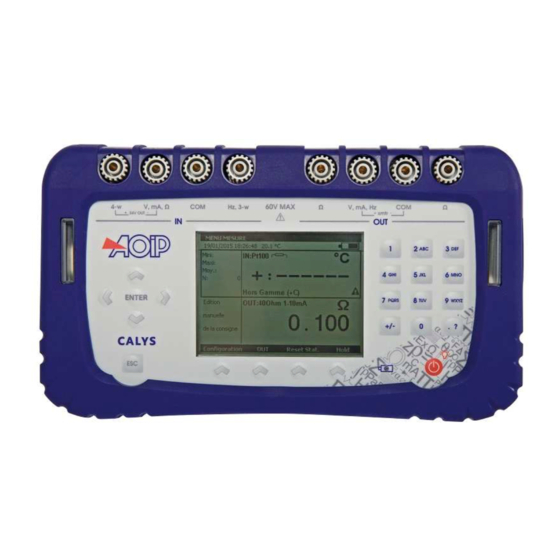
Quatre bornes pour le raccordement en fonction "émission/simulation" (OUT). Se reporter au paragraphe 0. Les 8 bornes du CALYS 50 / 75 / 100 sont « push & lock ». Elles acceptent les fiches bananes 4mm, les fils nus, les cosses à... -
Page 11: A.2.5 Écran
Matériel A.2.5 Écran Le CALYS 50 / 75 / 100 est doté d’un afficheur LCD graphique avec un rétro-éclairage à LED blanches. La résolution de l’afficheur est de 240 x 320 pixels. Pendant le fonctionnement de l’appareil, l'écran comporte : Une fenêtre destinée à... - Page 12 CALYS 50 / 75 / 100 GENERALITES Le navigateur : Une touche d’annulation : Une touche de Marche/arrêt de l’appareil et d'allumage/extinction du rétro-éclairage: Un appui court démarre l’appareil. Pendant le fonctionnement un appui court met en marche ou éteint l’éclairage. Un appui long de 2 secondes arrête l’appareil.
-
Page 13: A.2.7 Batteries Et Chargeur
Précautions à prendre si la charge batterie est faible: A la réception de votre CALYS 50 / 75 / 100 il est possible que la charge des batteries ne soit pas suffisante pour un fonctionnement optimal voire même pour un démarrage de l’appareil. -
Page 14: A.3 Directives Ce
CALYS 50 / 75 / 100 GENERALITES A.3 Directives CE A.3.1 Conformité aux directives en vigueur L'appareil est conforme aux directives en vigueur : - Directive sécurité 2006/95/CE avec la norme EN611010-1 - Directive CEM 2004/108/CE avec la norme EN61326-1 - Directive Radio 1999/5/CE avec les normes EN300-328 et EN301-489 La présente notice d'utilisation contient des textes d'information et d'avertissement qui doivent être respectés par... -
Page 15: A.4 Logiciel
A.4 Logiciel Le firmware du CALYS 50 / 75 / 100 est stocké dans une mémoire flash. Par suite, il est relativement facile de faire une mise à jour du firmware quand une nouvelle version est disponible. Se reporter au paragraphe A.6.1 pour des informations détaillées sur la mise à... - Page 16 CALYS 50 / 75 / 100 GENERALITES La fonction « aide en ligne » n’est pas visible sur le menu. Elle est accessible à tout moment en exerçant un appui long sur la touche . Lorsqu’elle est activée, une fenêtre d’aide sur la fonction en cours d’utilisation apparaît. La touche permet de fermer la fenêtre d’aide et toutes les boites de dialogues affichées.
- Page 17 Par exemple, Il est possible de changer l’état du champ « Alimentation boucle » d’OFF à ON avec la touches navigation Bas et Haut. Pendant le fonctionnement du CALYS 50 / 75 / 100 plusieurs symboles sont affichés pour faciliter la sélection et l’indication des fonctions en cours. Ces symboles sont résumés dans le tableau suivant :...
- Page 18 CALYS 50 / 75 / 100 GENERALITES Symbole Description Touches de fonction Touche de tabulation Ouvrir une liste déroulant Fermer une liste déroulant Effacer l’élément sélectionné Arrêt de l’émission en cours Suspension de l’émission en cours Commencer ou reprendre l’émission Lancer l’émission dans le sens croissant...
-
Page 19: A.5 Securite
Sécurité A.5 Sécurité A.5.1 Conformité aux normes de sécurité L'appareil a été construit et essayé conformément à la norme européenne EN 61010-1 : règles de sécurité pour les appareils de mesures électroniques. La présente notice d'utilisation contient des textes d'information et d'avertissement qui doivent être respectés par l'utilisateur pour sa protection contre les dangers du courant électrique, assurer un fonctionnement sûr de l'appareil, et le préserver contre toute fausse manœuvre pouvant l'endommager ou détériorer sa sécurité... -
Page 20: A.5.5 Définitions
CALYS 50 / 75 / 100 GENERALITES A.5.5 Définitions A.5.5.1 Définition de la catégorie d'installation Cette notion est appelée aussi catégorie de surtension. C'est la classification de l'installation suivant des limites normalisées pour les surtensions transitoires (norme CEI 664). A.5.5.2 Tableau des symboles utilisés... -
Page 21: A.6 Services
Configuration propos. La façon la plus rapide pour vérifier si une mise à jour est disponible est de visiter le site web d’AOIP S.A.SErreur ! Nom de propriété de document inconnu. et regarder la page « Logiciels ». Pour effectuer la mise à jour du firmware, réaliser les opérations suivantes : Si nécessaire, installer sur le PC le pilote USB de communication avec les appareils AOIP. -
Page 22: A.6.2 Recalibration
Soit retourner l'appareil à l'adresse indiquée au début de ce guide pour vérification et ajustage. Il est possible d’effectuer un ajustage du CALYS 50 / 75 / 100 en utilisation un instrument dont la précision est meilleure que 50 ppm. Pour ajuster l’appareil utiliser le menu... - Page 23 Services Pour ajuster le CALYS 50 / 75 / 100 utiliser la touché de fonction REGLAGE. Effectuer les opérations de réglage dans l’ordre suivant : Mesure Auto-Ajustage Offsets Ohms Emission Date d’étalonnage Pour chaque type d’étalonnage sélectionner la fonction à étalonner avec les touches de navigation Haut et Bas et suivre les instructions indiquées dans les boites de dialogues.
-
Page 24: A.6.3 Nettoyage
Nettoyage Si le CALYS 50 / 75 / 100 a besoin d’être nettoyé utiliser un tissu imbibé d’une solution de nettoyage non dissolvante. Arrêter l’appareil et essuyer la gaine et le clavier si nécessaire. L’introduction de tout liquide à l’intérieure de l’appareil risque de l’endommager définitivement. -
Page 25: Mise En Route
Mise en route B. PRISE EN MAIN Afin d'utiliser l'appareil avec toute la sécurité nécessaire, tout opérateur doit lire attentivement le paragraphe A.1 (page 19) qui, entre autres, traite de la sécurité avant toute prise en main. Il est conseillé de lire aussi les paragraphes suivants : A.1.2 Déballage (page 8) A.2.7 NTA47227-300A8... -
Page 26: B.1 Mise En Route
/arrêt pendant une seconde. Après le démarrage, le CALYS 50 / 75 / 100 se met par défaut en mesure de tension et en émission de tension. Connecter la sortie Volt sur l’entrée Volt comme indiqué sur la figure suivante. - Page 27 Mise en route Pour choisir une fonction de mesure, activer la touche F1 (configuration). Sélectionner le menu Fonction … avec les touches de navigation et valider par la touche ENTER. Une boite de dialogue CONFIGURATION MESURE s’affiche. Les branchements en mode mesure se font sur les quatre bornes « IN » situées dans la moitié gauche de l’appareil: NTA47227-300A8 27 / 164...
-
Page 28: B.2.1 Mesure De Tension Continue
CALYS 50 / 75 / 100 PRISE EN MAIN B.2.1 Mesure de tension continue Afficher la boite de dialogue CONFIGURATION MESURE Sélectionner la fonction de mesure puis le calibre adapté à la mesure à l’aide des touches de fonction et de navigation. - Page 29 Mesure Dans ce cas, le CALYS 50 / 75 / 100 alimente un transmetteur passif en 24V et mesure en même temps le courant établi par le transmetteur. NTA47227-300A8 29 / 164...
- Page 30 CALYS 50 / 75 / 100 PRISE EN MAIN Si l’alimentation de la boucle est désactivée le branchement se fait entre les bornes mA et COM. Lorsque la mise à l’échelle quadratique est activée, le calibrateur prend la racine carrée de son entrée et affiche le résultat en pourcentage.
-
Page 31: B.2.3 Mesure De Résistance
Mesure Le CALYS 50 / 75 / 100 affiche dans la fenêtre une indication sur la configuration choisie à l’aide des icônes suivantes : : Pour indiquer une Alimentation de boucle désactivée : Pour indique une Alimentation de boucle activée : Pour indique une échelle quadratique... -
Page 32: B.2.4 Test De Continuité
Valider par ENTER. Le CALYS 50 / 75 / 100 effectue une mesure de résistance dans ce mode et affiche « ouvert » si la résistance mesurée est supérieure à 1000 Ohms et « fermé » si la résistance mesurée est inférieure à 1000 Ohms. -
Page 33: B.2.5 Mesure De Fréquence
Mesure B.2.5 Mesure de fréquence Afficher la boite de dialogue CONFIGURATION MESURE Sélectionner la « fonction de mesure » Fréquence puis le « type d’entrée » Signal à l’aide des touches de fonction et de navigation. Valider par ENTER. Le branchement se fait entres les bornes Hz et COM. L’unité... -
Page 34: B.2.7 Comptage D'impulsion
CALYS 50 / 75 / 100 PRISE EN MAIN B.2.7 Comptage d’impulsion Afficher la boite de dialogue CONFIGURATION MESURE Sélectionner la « fonction de mesure » Comptage puis le « type d’entrée » Signal Contact sec à l’aide des touches de fonction et de navigation. -
Page 35: B.2.8 Mesure Sondes Résistives (Température)
Cu 10 (α = 427) Cu 50 (α = 428) α étant le coefficient de température de la sonde. Le CALYS 50 / 75 / 100 affiche un pictogramme représentant le montage utilisé ( pour 2 fils, pour 3 fils ou 4 fils) pour effectuer la mesure. -
Page 36: B.2.9 Mesure Thermocouple (Température)
CALYS 50 / 75 / 100 PRISE EN MAIN B.2.9 Mesure Thermocouple (Température) Afficher la boite de dialogue CONFIGURATION MESURE Sélectionner la « fonction de mesure » puis le « type de couple » approprié à l’aide des touches de fonction et de navigation. -
Page 37: B.2.10 Mesure De Pression
B.2.11 Mesure de pression et détection d’ouverture de contact Le CALYS 50 / 75 / 100 permet de détecter l’ouverture ou la fermeture de contact (switch) et d’acquérir la valeur de la pression à l’instant du changement d’état de ce dernier. - Page 38 CALYS 50 / 75 / 100 PRISE EN MAIN Sélectionner le type de détection (Ouverture, Fermeture ou Ouverture et fermeture) et valider. Dès la validation du type de détection, chaque changement (sélectionné) sera détecté et la valeur de pression mesurée à...
-
Page 39: B.3 Generation / Simulation
Génération / Simulation B.3 Génération / Simulation L’accès aux fonctions d’émission/simulation s’effectue à partir de la touche de fonction F2 (OUT). L’appui sur cette touche rend la fenêtre d’émission/simulation active : Un rectangle entoure alors la fenêtre inférieure de l’écran. La touche F2 permet le passage du mode OUT au mode IN... -
Page 40: B.3.1 Génération De Tension Continue
CALYS 50 / 75 / 100 PRISE EN MAIN B.3.1 Génération de tension continue Afficher la boite de dialogue CONFIGURATION EMISSION Sélectionner la fonction d’émission puis le calibre adapté à la mesure à l’aide des touches de fonction et de navigation. -
Page 41: B.3.2 Génération De Courant
Une fois la mise à l’échelle activée l’utilisateur saisie les valeurs à simuler dans l’unité de la nouvelle échelle. Le CALYS 50 / 75 / 100 affiche dans la fenêtre une indication sur la configuration choisie à l’aide des icônes suivantes : : Pour indiquer une Alimentation de boucle désactivée... -
Page 42: B.3.3 Simulation De Résistance
CALYS 50 / 75 / 100 PRISE EN MAIN B.3.3 Simulation de résistance Afficher la boite de dialogue CONFIGURATION EMISSION Sélectionner la fonction de mesure Ohms puis le calibre à l’aide des touches de fonction et de navigation. Sélectionner le courant de mesure Valider par ENTER. -
Page 43: B.3.4 Simulation Sondes Résistives (Température)
Génération / Simulation B.3.4 Simulation sondes résistives (température) Afficher la boite de dialogue CONFIGURATION EMISSION Sélectionner la « fonction d’émission » puis le « type de sonde » approprié à l’aide des touches de fonction et de navigation. Sélectionner le courant de mesure Sélection l’unité... -
Page 44: B.3.5 Simulation De Thermocouple (Température)
CALYS 50 / 75 / 100 PRISE EN MAIN B.3.5 Simulation de thermocouple (température) Afficher la boite de dialogue CONFIGURATION EMISSION Sélectionner la « fonction d’émission » puis le « type de couple » approprié à l’aide des touches de fonction et de navigation. -
Page 45: B.3.6 Génération De Fréquence
Génération / Simulation B.3.6 Génération de fréquence Afficher la boite de dialogue CONFIGURATION EMISSION Sélectionner la « Fonction d’émission » Fréquence puis le calibre à l’aide des touches de fonction et de navigation. Sélectionner le « Type de Sortie » Signal. Saisir l’amplitude du signal entre 0 et 20 V Valider par ENTER. -
Page 46: B.3.7 Génération De Fréquence Sur Contact Sec
CALYS 50 / 75 / 100 PRISE EN MAIN B.3.7 Génération de fréquence sur contact sec Afficher la boite de dialogue CONFIGURATION EMISSION Sélectionner la « Fonction d’émission » Fréquence puis le calibre à l’aide des touches de fonction et de navigation. -
Page 47: B.3.8 Génération D'impulsions
Génération / Simulation B.3.8 Génération d’impulsions Afficher la boite de dialogue CONFIGURATION EMISSION Sélectionner la « Fonction d’émission » Impulsions puis le calibre à l’aide des touches de fonction et de navigation. Sélectionner le « Type de Sortie » Signal. Saisir l’amplitude du signal entre 0 et 20 V Valider par ENTER. - Page 48 CALYS 50 / 75 / 100 PRISE EN MAIN Pendant la génération des impulsions une barre de progression indique l’état d’avancement. Les touches de fonction permettent de contrôler la génération : La touche permet d’arrêter à tout moment la génération La touche permet de suspendre la génération...
-
Page 49: Operations Avancees
C. OPERATIONS AVANCEES C.1 Modes de simulation Plusieurs modes de fonctionnement pour l’émission sont disponibles dans le CALYS 50 / 75 / 100 pour faciliter la vérification rapide et la calibration des instruments et des transmetteurs. Pour changer le mode d’émission activer la fenêtre émission à l’aide de la touche de fonction (F2). -
Page 50: C.1.2 Mode Edition Incrémentale
CALYS 50 / 75 / 100 OPERATIONS AVANCEES C.1.2 Mode Edition incrémentale Lorsque ce mode est activé le pictogramme apparaît dans la fenêtre d’émission. Utiliser les 4 touches du navigateur pour éditer la valeur à émettre. Pour sélectionner un digit utiliser les touches Gauche et Droite du navigateur. - Page 51 Modes de simulation Les touches Haut/Bas du navigateur permettent de sélectionner la consigne dans la liste. La touche ENTER permet d’émettre la consigne sélectionnée. Les touches Gauche/Droite du navigateur permettent d’émettre la consigne précédente/Suivante. Les touches numériques 0 - 9 permettent de saisir au clavier la valeur à émettre. Dans le cas des valeurs prédéfinies en pourcentage de la pleine échelle le pictogramme apparaît à...
-
Page 52: C.1.4 Mode Marches D'escalier
CALYS 50 / 75 / 100 OPERATIONS AVANCEES C.1.4 Mode Marches d’escalier Ce mode permet de programmer une progression incrémentale de la fonction d’émission active. Lorsque ce mode est activé le pictogramme apparaît dans la fenêtre d’émission. La touche de fonction permet de lancer un cycle d’incréments croissants et la touche... -
Page 53: C.1.5 Mode Rampe Simple
Modes de simulation Pendant la génération d’une marche d’escalier une barre de progression indique l’état d’avancement. Les touches de fonction permettent de contrôler la génération : La touche permet d’arrêter à tout moment la génération La touche permet de suspendre la génération La touche permet de commencer ou reprendre la génération Le pictogramme... -
Page 54: C.1.6 Mode Rampe Cyclique
CALYS 50 / 75 / 100 OPERATIONS AVANCEES C.1.6 Mode rampe cyclique La fonction génération de rampe cyclique permet de programmer une première variation linéaire dans un sens (croissant ou décroissant) suivi par un premier palier et puis une deuxième variation linéaire dans le sens opposé de la première variation suivi par un deuxième palier. -
Page 55: C.1.7 Mode Synthétiseur
Modes de simulation C.1.7 Mode synthétiseur La fonction synthétiseur permet : de stocker en mémoire permanente jusqu’à 100 valeurs d’émission, de rappeler et d’émettre manuellement ou automatiquement le contenu de ces mémoires. Lorsque ce mode est activé le pictogramme apparaît dans la fenêtre d’émission. La touche de fonction permet de lancer la génération des valeurs dans l’ordre croissant et la touche permet de... -
Page 56: C.1.8 Mode Transmetteur
CALYS 50 / 75 / 100 OPERATIONS AVANCEES Utiliser les touches de fonction : pour supprimer un point pour ajouter un point pour éditer un point Utiliser les touches pour émettre les points selon les paramètres définis. Pendant la génération une barre de progression indique l’état d’avancement. Les touches de fonction permettent de contrôler la génération :... -
Page 57: C.2 Mise A L ' Echelle
Mise à l'échelle C.2 Mise à l’échelle La fonction de correction d’échelle effectue les opérations de conversion entre les grandeurs électriques mesurées et les grandeurs physiques converties. Cette opération de linéarisation permet de corriger partiellement les erreurs induites par des systèmes capteurs/convertisseurs non linéaires. -
Page 58: C.3 Mesures Differentielles
CALYS 50 / 75 / 100 OPERATIONS AVANCEES C.3 Mesures différentielles La fonction mesure relative de l'appareil permet : de programmer une valeur de référence différente de celle de l’appareil (fonction NUL), d’annuler par mesure ou programmation une valeur constante ou parasite (fonction TARE). -
Page 59: C.4 Capteurs Etalonnes
Capteurs étalonnés C.4 Capteurs étalonnés La fonction capteurs étalonnés de l'appareil permet d’utiliser des capteurs dont les coefficients d’étalonnage (de correction) sont pris en compte par l’appareil lors de la mesure. Afficher la boite de dialogue CONFIGURATION MESURE. Sélectionner la fonction CAPTEURS ETALONNES. - Page 60 CALYS 50 / 75 / 100 OPERATIONS AVANCEES Pour entrer dans le tableau des points d’étalonnage, utiliser la touche Entrer les valeurs et valider. Utiliser les touches suivantes pour continuer le paramétrage du capteur : pour éditer un point déjà édité...
-
Page 61: C.5 Procedure D ' Etalonnage
Procédure d'étalonnage Dans le cas particulier où un seul point d’étalonnage est indiqué, le comportement est différent selon que le capteur est un thermocouple ou une résistance thermométrique : . Dans le cas d’un thermocouple, la correction est un écart fixe de tension. . - Page 62 CALYS 50 / 75 / 100 OPERATIONS AVANCEES Utiliser les touches suivantes pour définir les points. pour éditer un point déjà édité pour ajouter un point pour supprimer un point A partir de la touche de fonction F1 ( ), sélectionner le champ mode d’émission.
- Page 63 Procédure d'étalonnage Définir les conditions de tests (limites) en appuyant sur F3 (Conditions). Après avoir défini les limites, valider par ENTER. Valider par ENTER. Pour exécuter cette procédure, appuyer sur la touche F3 (Exécuter). NTA47227-300A8 63 / 164...
- Page 64 CALYS 50 / 75 / 100 OPERATIONS AVANCEES Après avoir renseigné les champs, lancer l’exécution en appuyant sur la touche F3 (Exécuter). Dans le cas où la procédure est exécutée manuellement, l’utilisateur devra valider un à un tous les ponts d’étalonnage.
-
Page 65: C.6 Memorisation Des Acquisitions En Cours
Mémorisation des acquisitions en cours C.6 Mémorisation des acquisitions en cours Attention cette fonctionnalité n’est disponible uniquement que pour les modèles CALYS 75 et CALYS 100. Le CALYS 75 / 100 est capable de mémoriser 10 000 valeurs en une ou plusieurs salves d’acquisition. Utiliser si nécessaire la touche F2 pour activer la fenêtre ‘IN’... - Page 66 CALYS 50 / 75 / 100 OPERATIONS AVANCEES Dans le cas de la sélection d’un trigger niveau bas niveau haut, il est nécessaire de définir le niveau de déclenchement et le nombre de données à enregistrer après ce déclenchement. Taille du bloc (2 500 mesures) Post trigger = 1000 mesures Déclenchement...
- Page 67 Mémorisation des acquisitions en cours En appuyant sur les touches de navigation gauche ou droite il est possible de déplacer le curseur et de lire la valeur en abscisse et ordonnée. Il est possible à ce niveau de redéfinir les marqueurs afin de faire un zoom entre ces deux nouveaux points : Dans le champ X, entrer une valeur qui sera la valeur basse du marqueur (X1), valider par ENTER et appuyer sur la touche de fonction F2 (X 1).
- Page 68 CALYS 50 / 75 / 100 OPERATIONS AVANCEES Nouvelle salve libre: Permet de débuter une nouvelle salve. Dans le cas où une salve est en cours, il sera demandé de sauvegarder celle-ci. Gestion des salves : Permet de visualiser toutes les salves enregistrées. Il est possible, à ce niveau, de renommer une salve ou d’effacer une ou toutes les salves.
-
Page 69: C.7 Configurations
Configurations C.7 Configurations Une configuration représente l’état du CALYS 50 / 75 / 100 à un moment donné. L’état de l’appareil inclut : Les fonctions et les calibres en cours en mesure et en simulation Les paramètres de tous les modes d’émission (marche d’escalier, rampe, synthétiseur, etc...) Les mises à... -
Page 70: C.8 Parametrage
Réglage de contraste Utiliser les touches de navigation Droit et Gauche pour ajuster le contraste de l’afficheur. Le CALYS 50 / 75 / 100 sauvegarde le réglage effectué dans sa mémoire non volatile. Il utilise le réglage effectué à chaque démarrage de l’appareil. -
Page 71: C.8.3 Préférences
Paramétrage C.8.3 Préférences Pour afficher la boite de dialogue Préférences utiliser le menu Configuration Setup. Préférences…. Les paramètres réglables sont : Filtrage : Permet de moyenner les mesures avant l’affichage. Quand le filtrage est désactivé le temps d’intégration des mesures est de 0,5 seconde. Résolution : Permet de régler la résolution des mesures lors de l’affichage. -
Page 72: Specifications Techniques
CALYS 50 / 75 / 100 SPECIFICATIONS TECHNIQUES D. SPECIFICATIONS TECHNIQUES Les expressions de précision citées s'appliquent de + 18°C à + 28°C, sauf mention contraire, et sont exprimées en ± (n % L + C) avec L = Lecture et C = Constante exprimée en unité pratique. Les spécifications sont données pour un intervalle de confiance de 95%. -
Page 73: Température Par Couples Thermoélectriques (Calys 50 / 75)
Circuit Ouvert pour R > 1000 Ω. Circuit Fermé pour R < 1000 Ω. D.1.4 Température par couples thermoélectriques (CALYS 50 / 75) Type de capteurs : - Normalisés selon CEI 584-1/1995 (Couples K, T, J, E, S, B, N). -
Page 74: D.1.5 Température Par Sondes À Résistance (Calys 50 / 75)
Il est possible, couple B excepté, de choisir par programmation au clavier la localisation de la jonction de référence : externe à 0°C, interne (compensation de la température des bornes de l'appareil). par programmation de la température. D.1.5 Température par sondes à résistance (CALYS 50 / 75) Capteur Etendue de mesure Résolution Précision / 1 an Pt 50 (α... -
Page 75: D.1.6 Fréquence Et Comptage (Calys 50 / 75 / 100)
Fonction Mesure D.1.6 Fréquence et comptage (CALYS 50 / 75 / 100) Calibre Résolution Gamme Précision / 1 an Remarques 20 kHz 0,01 Hz 1 Hz à 20 KHz 0,005% L + 5 mHz Coefficient de température < 5 ppm L/°C de -10°C à +18°C et de +28°C à +50 °C. -
Page 76: D.1.10 Température Par Couples Thermoélectriques (Calys 100)
CALYS 50 / 75 / 100 SPECIFICATIONS TECHNIQUES D.1.10 Température par couples thermoélectriques (CALYS 100) Type de capteurs : - Normalisés selon CEI 584-1/1995 (Couples K, T, J, E, S, B, N). - Selon Din 43710 (couples U et L). -
Page 77: D.1.11 Température Par Sondes À Résistance (Calys 100)
Tenir compte, en outre, de l'erreur propre du capteur de température utilisé et des conditions de sa mise en œuvre. Courant de mesure : 0,25 mA D.1.12 Caractéristiques complémentaires en "mesure" (CALYS 50 / 75 / 100) D.1.12.1 Changement de calibre manuel ou automatique Pour les fonctions mV, V et Ω, en changement de calibre automatique, l'appareil passe sur le calibre supérieur ou... -
Page 78: D.2 Fonction " Emission / Simulation
Temps d'établissement : < 5 ms. Ces spécifications sont données pour les configurations suivantes :- - CALYS 50 / 75 / 100 mode actif (+24 V ON) Mesureur mode passif (+24 V OFF). - CALYS 50 / 75 / 100 mode passif (+24 V OFF) Mesureur mode actif (+24 V ON) D.2.3... -
Page 79: D.2.4 Température Par Couples Thermoélectriques (Calys 50 / 75)
Fonction "Emission / Simulation" D.2.4 Température par couples thermoélectriques (CALYS 50 / 75) Type de capteurs : - Normalisés selon CEI 584-1/1995 (Couples K, T, J, E, S, B, N). - Selon Din 43710 (couples U et L). - Selon la table d’ENGELHARD (couple Platine) - Selon la norme ASTM E 1751-00 (couple G) - Selon la norme ASTM E 988-96 (couple D W3Re/W25Re ;... -
Page 80: D.2.5 Température Par Sondes À Résistance (Calys 50 / 75)
CALYS 50 / 75 / 100 SPECIFICATIONS TECHNIQUES D.2.5 Température par sondes à résistance (CALYS 50 / 75) Capteur Etendue de mesure Résolution Précision / 1 an Pt 50 (α = 3851) - 220°C + 1 200°C 0,03°C 0,014% L + 0,18°C - 220°C + 850°C... -
Page 81: D.2.6 Fréquence (Calys 50 / 75 / 100)
Temps d'établissement : < 5 ms. Ces spécifications sont données pour les configurations suivantes :- - CALYS 50 / 75 / 100 mode actif (+24V ON) Mesureur mode passif (+24 V OFF). - CALYS 50 / 75 / 100 mode passif (+24V OFF) Mesureur mode actif (+24 V ON) D.2.9... -
Page 82: D.2.10 Température Par Couples Thermoélectriques (Calys 100)
CALYS 50 / 75 / 100 SPECIFICATIONS TECHNIQUES D.2.10 Température par couples thermoélectriques (CALYS 100) Type de capteurs : - Normalisés selon CEI 584-1/1995 (Couples K, T, J, E, S, B, N). - Selon Din 43710 (couples U et L). -
Page 83: D.2.11 Température Par Sondes À Résistance (Calys 100)
Ni 120 Ohms avec α =672 selon la publication MIL-T-24388C Cu 10 Ohms avec α =427 selon la publication MINCO 16/9 D.2.12 Caractéristiques complémentaires en simulation (CALYS 50 / 75 / 100) D.2.12.1 Génération d'incréments La fonction génération d'incréments permet de programmer une progression incrémentale de la fonction d'émission active. - Page 84 CALYS 50 / 75 / 100 Multifunction Process Calibrator Instruction manual 84 / 164 NTA47227-300A8...
- Page 85 Parts, repairs to the product and service are guaranteed for a period of 90 days. This guarantee only applies to the original purchaser or the end user if he is a client of an AOIP S.A.S approved distributor and does not cover fuses, interchangeable batteries/cells nor any product which, in the opinion of AOIP S.A.S, has been...
- Page 86 CALYS 50 / 75 / 100 TABLE OF CONTENTS Table of contents GENERAL .................................. 88 ................................88 NTRODUCTION A.1.1 About this guide ..............................89 A.1.2 Unpacking ................................89 A.1.3 Returning ................................89 ................................. 90 ATERIAL A.2.1 General view of the unit ............................90 A.2.2 Sheath .................................
- Page 87 D.1.9 Resistance (CALYS 100) ..........................154 D.1.10 Temperature by thermocouples (CALYS 100) ....................155 D.1.11 Temperature using resistive probes (CALYS 100) ..................156 D.1.12 Additional characteristics in "measurement" (CALYS 50 / 75 / 100) ............... 156 "T " ........................157...
-
Page 88: General
A.1 Introduction The CALYS 50 / 75 / 100 is a multifunction calibrator. It is specially designed for calibration and maintenance and can measure and simulate physical and electrical quantities, either on site or in the laboratory. -
Page 89: A.1.1 About This Guide
A.1.2 Unpacking All CALYS 50 / 75 / 100 units are mechanically and electrically checked before delivery. The necessary precautions have been taken to ensure that they reach the user undamaged. However, it is a good idea to make a brief check for any damage that may have occurred during transportation. If this is the case, make an immediate claim against the carrier. -
Page 90: A.2 Material
Sheath The CALYS 50 / 75 / 100 is delivered with a rubber sheath fitted to the case. The sheath protects the unit from mechanical shocks and makes the side openings for the USB interface connector and the charger connector waterproof to IP54. -
Page 91: A.2.3 Connection Terminals
Four connection terminals for the "transmit/simulate" function (OUT). Refer to paragraph D.2. The 8 terminals of the CALYS 50 / 75 / 100 are of the “push & lock” type. They accept 4 mm banana plugs, bare wires, spade terminals and miniature connectors for thermocouples. -
Page 92: A.2.5 Screen
A.2.5 Screen The CALYS 50 / 75 / 100 is fitted with an LCD graphical display which is backlit with white LEDs. The resolution of the display is 240 x 320 pixels. When the unit is in use, the screen comprises: A window displaying the programming of the "measurement"... - Page 93 Material A navigator: A cancel key: A Start/stop key for the unit and back-lighting on/off key: A short push switches the unit on. During operation, a short push switches the back-lighting on or off. A long push of 2 seconds switches the unit off. A long push of 6 seconds resets the unit in case of lock. 12 alphanumeric keys for programming the parameters.
-
Page 94: A.2.7 Batteries And Charger
A.2.10 Stand The stand gives a good angle of view when the CALYS 50 / 75 / 100 is placed on a desk. Unfold the stand on the back of the unit and place the CALYS 50 / 75 / 100 on a desk as shown below. -
Page 95: A.3 Ce Directives
CE directives A.3 CE directives A.3.1 Compliance with safety standards The unit complies with applicable standards: - Safety directive 2006/95/CE with standard EN611010-1 - Directive CEM 2004/108/CE with standard EN61326-1 These instructions for use contain information and warnings which must be observed by the user to protect the latter against the dangers of electricity, to ensure the safe operation of the device and to protect it against any mishandling which could damage or compromise the safety of use of the device. -
Page 96: A.4 Software
A.4 Software The firmware of the CALYS 50 / 75 / 100 is stored in flash memory. It is therefore relatively easy to update the firmware when a new version is available. Refer to paragraph A.6.1 for detailed information on updating the firmware. - Page 97 Software Navigation within menus and sub-menus is by means of the navigation keys and the ENTER key. For example, to display the% FS menu in the example of the screen below, perform the following steps: 1) Press the F4 key associated with the proposed Mode from the main menu. 2) Press the Down navigation key twice to select the Predefined settings sub-menu and confirm with the ENTER key.
- Page 98 OFF to ON using the Down and Up navigation keys. During operation of the CALYS 50 / 75 / 100, several symbols are displayed to simplify selection and indication of the current functions. These symbols are shown in the table below:...
- Page 99 Software Symbol Description Function keys Tabulation key Open a drop-down list Close a drop-down list Cancel the selected item Stop the current transmission Suspend the current transmission Commence or resume transmission Launch transmission in the increasing direction Launch transmission in the decreasing direction Transmit synthesised points in the order entered Transmit synthesised points in the reverse order Cancel the selection...
-
Page 100: A.5 Safety
CALYS 50 / 75 / 100 GENERAL A.5 Safety A.5.1 Compliance with safety standards The unit is built and tested in accordance with European standard EN 61010-1: safety rules for electronic measuring equipment. These user instructions contain information and warning notices which must be respected by the user for protection against danger from electric currents, ensuring correct operation of the unit and protection against any false step that could damage the unit or make it unsafe to use. -
Page 101: A.5.5 Definitions
Safety A.5.5 Definitions A.5.5.1 Definition of the installation category This is also known as the overvoltage category. It is the classification of the installation according to standard limits for transient overvoltages (standard CEI 664). A.5.5.2 Table of symbols used Symbol Description Warning: see accompanying documents Earth point... -
Page 102: A.6 Service
Configuration About menu. The quickest way to find out if an update is available is to visit the AOIP S.A.S website and look at the “Software” page. To update the firmware, proceed as follows: 1) If necessary, install on the PC the USB driver for communication with AOIP instruments. -
Page 103: A.6.2 Recalibration
Or return the unit to the address shown at the start of this guide for checking and adjustment. It is possible to adjust the CALYS 50 / 75 / 100 using an instrument whose accuracy is better than 50 ppm. To adjust the unit, select the Configuration Maintenance menus, then enter the password 9456. - Page 104 CALYS 50 / 75 / 100 GENERAL To adjust the CALYS 50 / 75 / 100, use the ADJUST function key. Make adjustments in the following order: Measurement Auto-Adjust Ohms Offsets Transmission Date of calibration For each type of calibration, select the function to be calibrated with the Up and Down navigation keys and follow the instructions shown in the dialogue boxes.
-
Page 105: A.6.3 Cleaning
Cleaning If the CALYS 50 / 75 / 100 needs cleaning, use a tissue soaked in a non-solvent cleaning solution. Switch off the unit and wipe the sheath and keyboard if necessary. If any liquid enters the unit it may cause irreparable damage. -
Page 106: Getting Started
(LED off) before switching on the unit by pressing the Start/stop key for one second. After starting, the CALYS 50 / 75 / 100 is set by default to voltage measurement and voltage transmission. Connect the Volts output to the Volts input as shown in the diagram below. - Page 107 Measurement To choose a measurement function, press key F1 (configuration). Select the Function … menu with the navigation keys and confirm with the ENTER key. The MEASUREMENT CONFIGURATION dialogue box is displayed. Connections in the measurement mode are made to the four “IN” terminals on the left half of the unit: NTA47227-300A8 107 / 164...
-
Page 108: B.2.1 Measuring Dc Voltage
CALYS 50 / 75 / 100 GETTING STARTED B.2.1 Measuring DC voltage Display the MEASUREMENT CONFIGURATION dialogue box: Select the Vdc measurement function then the correct measurement range using the function and navigation keys. Confirm with ENTER. The following ranges are available:... -
Page 109: B.2.2 Measuring Current
If loop power supply is on, the connection is made between terminals 4-w and mA. In this case, the CALYS 50 / 75 / 100 supplies a passive transmitter with 24 V and at the same time measures the current established by the transmitter. - Page 110 In the case of the 4-20 mA range, the scale curve is as follows: x (mA) The CALYS 50 / 75 / 100 displays in the window details of the selected configuration using the following icons: : To show loop power supply off...
-
Page 111: B.2.3 Measuring Resistance
The CALYS 50 / 75 / 100 displays an icon showing the connections used ( for 2 wire, for 3 wire or wire) to make the measurement. The wiring arrangement is automatically detected by the calibrator. -
Page 112: B.2.4 Continuity Test
Confirm with ENTER. The CALYS 50 / 75 / 100 makes a resistance measurement in this mode and displays “open” if the resistance measured is greater than 1000 Ohms and “closed” if the resistance measured is less than 1000 Ohms. -
Page 113: B.2.5 Measuring Frequency
Measurement B.2.5 Measuring frequency Display the MEASUREMENT CONFIGURATION dialogue box: Select the "Frequency measurement function, then the “type of input” Signal using the function and navigation keys. Confirm with ENTER. Connection is made between the Hz and COM terminals. The display unit may be in Hz or in beats per minute (BPM). The measurement resolution is 0.01 Hz. -
Page 114: B.2.7 Pulse Counting
CALYS 50 / 75 / 100 GETTING STARTED B.2.7 Pulse counting Display the MEASUREMENT CONFIGURATION dialogue box: Select the Counting measurement function, then the “type of input” Signal or Hard Contact using the function and navigation keys. Enter the counting time using the alphanumeric keys. -
Page 115: B.2.8 Resistive Temperature Probes (Temperature)
Cu 10 (α = 427) Cu 50 (α = 428) α is the temperature coefficient of the probe. The CALYS 50 / 75 / 100 displays an icon showing the connections used ( for 2 wires, for 3 wires or for 4 wires) to carry out the measurement. -
Page 116: B.2.9 Measurement By Thermocouple (Temperature)
CALYS 50 / 75 / 100 GETTING STARTED B.2.9 Measurement by Thermocouple (Temperature) Display the MEASUREMENT CONFIGURATION dialogue box: Select the Tc measurement function, then the appropriate “type of thermocouple” using the function and navigation keys. Select the display unit Select the type of cold junction (CSF) used. -
Page 117: B.2.10 Pressure Measurement
Measurement B.2.10 Pressure measurement CAUTION: Function only available for models CALYS 75 and CALYS 100. Open the MEASUREMENT CONFIGURATION dialog box, Select the Pressure measurement function. Select the unit (BAR, PSI, Pa, Atm, Kgcm2, cmHg, mmHg, inHgftH2O, inH2O). Press ENTER. Connect the pressure sensor on the right-hand side of the unit (see chapter, side connectors). -
Page 118: B.2.11 Pressure Measurement And Detection Of Contact Opening
B.2.11 Pressure measurement and detection of contact opening The CALYS 50 / 75 / 100 can detect the opening or closing of a contact (switch) and acquire the value of pressure at the moment that this change of state occurs. -
Page 119: B.3 Generation / Simulation
Generation / Simulation B.3 Generation / Simulation The transmission/simulation functions are selected by pressing the function button, F2 (OUT). Pressing this button activates the transmission/simulation window: the lower window in the display is then marked by a rectangular border. The F2 key will change the OUT mode to IN mode. -
Page 120: B.3.1 Generating A Dc Voltage
CALYS 50 / 75 / 100 GETTING STARTED B.3.1 Generating a DC voltage Display the TRANSMISSION CONFIGURATION dialogue box: Select the Vdc transmission function, then the range suitable for measurement using the function and navigation keys. Confirm with ENTER. The following ranges are available:... -
Page 121: B.3.2 Current Generation
Connection is made between the mA and COM terminals. If the loop power supply is on, the CALYS 50 / 75 / 100 simulates a passive transmitter supplied with 24 V internally. If the loop power supply is off, the CALYS 50 / 75 / 100 simulates a passive transmitter supplied with 24 V externally. -
Page 122: B.3.3 Resistance Simulation
CALYS 50 / 75 / 100 GETTING STARTED B.3.3 Resistance simulation Display the TRANSMISSION CONFIGURATION dialogue box: Select the Ohm measurement function Select the Idc measurement function, then the range using the function and navigation keys. Select the measurement current Confirm with ENTER. -
Page 123: B.3.4 Resistive Probe Simulation (Temperature)
Generation / Simulation B.3.4 Resistive probe simulation (temperature) Display the TRANSMISSION CONFIGURATION dialogue box: Select the Rt transmission function, then the appropriate “type of probe”, and range using the function and navigation keys. Select the measurement current Select the display unit Confirm with ENTER. -
Page 124: B.3.5 Thermocouple Simulation (Temperature)
CALYS 50 / 75 / 100 GETTING STARTED B.3.5 Thermocouple simulation (temperature) Display the TRANSMISSION CONFIGURATION dialogue box: Select the Tc transmission function, then the appropriate “type of thermocouple”, using the function and navigation keys. Select the display unit Select the type of cold junction compensation (CSF) used. Enter the temperature of the CSF in the case of a programmed CSF. -
Page 125: B.3.6 Frequency Generation
Generation / Simulation B.3.6 Frequency generation Display the TRANSMISSION CONFIGURATION dialogue box: Select the Frequency transmission function, then the range using the function and navigation keys. Select the Signal “Output type”. Enter the amplitude of the signal between 0 and 20 V. Confirm with ENTER. -
Page 126: B.3.8 Pulse Generation
CALYS 50 / 75 / 100 GETTING STARTED B.3.8 Pulse generation Display the TRANSMISSION CONFIGURATION dialogue box: Select the Pulse transmission function, then the range using the function and navigation keys. Select the “Type of Output” Signal. Enter the amplitude of the signal between 0 and 20 V. - Page 127 Generation / Simulation During pulse generation, a progress bar indicates the state of progress. The function keys can be used to control generation: key stops generation at any time key suspends generation key commences or resumes generation icon in the transmission window indicates suspended generation. B.3.8.1 Parameters Output type: Signal...
-
Page 128: Advanced Operation
To change the transmission mode, open the transmission window using the OUT function key (F2). When the transmission window is open, the CALYS 50 / 75 / 100 is set by default to the Manual edit mode. To access the other modes, select the Mode menu using function key F4. Select a transmission mode using the Up/Down keys of the navigator and confirm with ENTER. -
Page 129: C.1.2 Incremental Edit Mode
Simulation modes C.1.2 Incremental Edit mode When this mode is active, the icon appears in the transmission window. Use the 4 navigator keys to edit the value to be transmitted. To select a digit, use the Left and Right keys of the navigator. The editable digit appears reversed in the display (white on black). -
Page 130: C.1.3 Predefined Settings Mode
CALYS 50 / 75 / 100 ADVANCED OPERATION C.1.3 Predefined Settings mode This mode is available for the DC current transmission function for the 0-20 mA and 4-20 mA ranges only. Two types of predefined settings are offered: Valve Test and Percentage of full scale (% of FS). -
Page 131: C.1.4 Staircase Mode
Simulation modes C.1.4 Staircase mode This mode is used to program an incremental progression of the active transmission function. When this mode is active, the icon appears in the transmission window. function key launches a cycle of increasing increments and the function key launches a cycle of decreasing increments. - Page 132 CALYS 50 / 75 / 100 ADVANCED OPERATION During generation of a staircase, a progress bar indicates the state of progress. The function keys control generation: key stops generation at any time key suspends generation key commences or resumes generation icon in the transmission window indicates suspended generation.
-
Page 133: C.1.5 Simple Ramp Mode
Simulation modes C.1.5 Simple Ramp mode The simple ramp generation function is used to program a linear variation in one direction (increasing or decreasing) of the active transmission function. When this mode is active, the icon appears ion the transmission window. key is used to launch an increasing ramp and the function key is used to launch a decreasing ramp. -
Page 134: C.1.6 Cyclic Ramp Mode
CALYS 50 / 75 / 100 ADVANCED OPERATION C.1.6 Cyclic Ramp mode The cyclic ramp generation function is used to program a first linear variation in a direction (increasing or decreasing) followed by a first step and then a second linear variation in a direction opposite to the first variation followed by a second step. -
Page 135: C.1.7 Synthesizer Mode
Simulation modes C.1.7 Synthesizer mode The synthesizer function is used: to store up to 100 transmission values in permanent memory, to recall and transmit the contents of these memories manually or automatically. When this mode is active, the icon appears in the transmission window. key is used to launch generation of values in increasing order and the function key is used to launch generation of values in decreasing order. -
Page 136: C.1.8 Transmitter Mode
CALYS 50 / 75 / 100 ADVANCED OPERATION Use the function keys: To cancel a point To add a point To edit a point Use the keys to transmit points according to the parameters defined. During generation, a progress bar indicates the state of progress. The function keys are used to control generation:... -
Page 137: Caling
Simulation modes C.2 Scaling The scale correction function performs a conversion between the electrical quantities measured and the physical quantities converted. This linearization is used partially to correct errors induced by non-linear sensor/converter systems. The Set to scale function is used to define up to 10 segments of a straight line, or 10 points, in order to approach a non- linear response curve as closely as possible and to perform scale corrections for each segment. -
Page 138: C.3 Differential Measurements
CALYS 50 / 75 / 100 ADVANCED OPERATION C.3 Differential Measurements The relative measurement function of the unit is used: to program a reference value other than that of the unit (ZERO function), to cancel by measurement or programming a constant or interfering value (TARE function). -
Page 139: Calibration Procedure
Calibration procedure C.4 Calibrated sensors The unit’s calibrated sensors function makes it possible to use sensors of which the calibration (correction) factors can be taken into account by the unit at the time of measurement. Open the MEASUREMENT CONFIGURATION dialog box, Select the Calibrated Sensors function. - Page 140 CALYS 50 / 75 / 100 ADVANCED OPERATION To enter calibration points in the table, use the button. Enter the values and press ENTER. Use the following buttons to continue configuring a sensor. To edit an existing calibration point, To add a calibration point, To delete a calibration point.
-
Page 141: C.5 Calibration Procedure
Calibration procedure Sensors declared in this manner are added to the list of couple types (or of probe types) proposed in the measurement function settings dialog box. They appear at the top of the list, in front of the standard sensors. Their name is preceded by the '*' character, indicating that these are calibrated sensors. - Page 142 The settling time field can be used to define the time, in seconds, between sending the setting from the output of the CALYS 50 / 75 / 100 and making the measurement at its input. When all fields have been completed, press ENTER.
- Page 143 Calibration procedure Press F3 (conditions) to define the test conditions (limits). When the limits have been defined, press ENTER. Press ENTER again. To execute the procedure, press F3 (Execute). After completing the fields, start execution by pressing F3 (Execute). Where the procedure is executed manually, the user will have to confirm the calibration points one by one. NTA47227-300A8 143 / 164...
- Page 144 CALYS 50 / 75 / 100 ADVANCED OPERATION Calibration point requiring confirmation (press ENTER) If the transmission mode has been defined as One-Way or Two-Way, the procedure is executed automatically. Press the function button, F1, to store the calibration report.
-
Page 145: Toring The Current Acquisitions
CAUTION: Function only available for models CALYS 75 and CALYS 100. The CALYS 50 / 75 / 100 is capable of storing 10,000 values in one or more acquisition bursts. If necessary, use the F2 button to open the ‘IN’ window and display the Measurement menu bar. - Page 146 CALYS 50 / 75 / 100 ADVANCED OPERATION If high-level or low-level trigger is selected, the trigger level and number of data points to be stored after this trigger must be defined. Block size (2,500 measurements) Post trigger = 1000 measurement...
- Page 147 Storing the current acquisitions The left and right arrow buttons can be pressed to move the cursor and read off the abscissa and ordinate values. At this level, the markers can be redefined in order to zoom in between these two new points: in the X field, enter a low value for the marker (X1), press ENTER and then press the function button, F2 (X 1), In the X field, enter a high value for the marker (X2), press ENTER and then press the function button, F3 (X 2).
-
Page 148: C.7 Configurations
ADVANCED OPERATION C.7 Configurations A configuration is the state of the CALYS 50 / 75 / 100 at a given moment. The state of the unit includes: The current functions and ranges for measurement and simulation, The parameters of all the transmission modes (staircase, ramp, synthesizer, etc.), The scale corrections applied, All the preferences defined in paragraph C.8.3. -
Page 149: Etting Parameters
Adjustment of contrast Use the Right and Left navigation keys to adjust the contrast of the display. The CALYS 50 / 75 / 100 saves the setting made in its non-volatile memory and uses it each time the unit is switched on. -
Page 150: C.8.3 Preferences
CALYS 50 / 75 / 100 ADVANCED OPERATION C.8.3 Preferences To display the Preferences dialogue box, use the Configuration Setup Preferences… menus. The adjustable parameters are: Filtering: Used to average measurements before display. When filtering is switched off, the integration time for measurements is 0.5 seconds. -
Page 151: Technical Specifications
D.1 Measurement Function Measurement rate: 0.5 s per measurement. Maximum rated voltage in common mode: 60 VDC or VAC. D.1.1 DC Voltage (CALYS 50 / 75) Range Resolution Accuracy / 1 year Notes ±100 mV 1 µV... -
Page 152: D.1.4 Temperature By Thermocouples (Calys 50 / 75)
Open circuit for R > 1000 Ω. Closed circuit for R < 1000 Ω. D.1.4 Temperature by thermocouples (CALYS 50 / 75) Sensor types: - In accordance with CEI 584-1/1995 (couples K, T, J, E, S, B, N), - In accordance with Din 43710 (couples U and L), - In accordance with the ENGELHARD table (platinum couple). -
Page 153: D.1.5 Temperature Using Resistive Probes (Calys 50 / 75)
The above accuracy is given for 4 wire connection of the temperature sensor. Taking into account, also, the intrinsic error of the temperature sensor used and its conditions of use. Measurement current: 0.25 mA D.1.6 Frequency and counting (CALYS 50 / 75 / 100) Range Resolution Accuracy / 1 year... -
Page 154: D.1.8 Dc Current (Calys 100)
CALYS 50 / 75 / 100 TECHNICAL SPECIFICATIONS - Range 10V : < (6 ppm R + 1 ppm Cal) /°C, - Range 50V : < (5 ppm R + 2 ppm Cal) /°C. Use the absolute value of the value measured (|L|) to calculate the accuracy. -
Page 155: D.1.10 Temperature By Thermocouples (Calys 100)
Measurement function D.1.10 Temperature by thermocouples (CALYS 100) Sensor types: - In accordance with CEI 584-1/1995 (couples K, T, J, E, S, B, N), - In accordance with Din 43710 (couples U and L), - In accordance with the ENGELHARD table (platinum couple). - As per standard ASTM E 1751-00 (G couple) - As per standard ASTM E 988-96 (D W3Re/W25Re couple;... -
Page 156: D.1.11 Temperature Using Resistive Probes (Calys 100)
Taking into account, also, the intrinsic error of the temperature sensor used and its conditions of use. Measurement current: 0.25 mA D.1.12 Additional characteristics in "measurement" (CALYS 50 / 75 / 100) D.1.12.1 Manual or automatic range selection For the mV, V and Ω functions, with automatic range selection, the unit selects a higher or lower range. -
Page 157: D.2 "Transmission / Simulation" Function
Settling time: < 5 ms The above specifications are given for the following configurations:- - CALYS 50 / 75 / 100 active mode (+24 V ON) Passive mode tester (+24 V OFF). - CALYS 50 / 75 / 100 passive mode (+24 V OFF) Active mode tester (+24 V ON). -
Page 158: D.2.4 Temperature By Thermocouples (Calys 50 / 75)
CALYS 50 / 75 / 100 TECHNICAL SPECIFICATIONS D.2.4 Temperature by thermocouples (CALYS 50 / 75) Sensor types: - In accordance with CEI 584-1/1995 (couples K, T, J, E, S, B, N), - In accordance with Din 43710 (couples U and L), - In accordance with the ENGELHARD table (platinum couple). -
Page 159: D.2.5 Temperature By Resistive Probes (Calys 50 / 75)
Transmission / Simulation Function D.2.5 Temperature by resistive probes (CALYS 50 / 75) Sensor Range of measurement Resolution Accuracy/1 year - 220°C + 1,200°C 0.03°C 0.014% R + 0.18°C Pt 50(α = 3851) - 220°C + 1,200°C 0.02°C 0.014% R + 0.12°C Pt 100 (α... -
Page 160: D.2.6 Frequency (Calys 50 / 75 / 100)
Settling time: < 5 ms The above specifications are given for the following configurations:- - CALYS 50 / 75 / 100 active mode (+24 V ON) Passive mode tester (+24 V OFF). - CALYS 50 / 75 / 100 passive mode (+24 V OFF) Active mode tester (+24 V ON) D.2.9... -
Page 161: D.2.10 Temperature By Thermocouples (Calys 100)
Transmission / Simulation Function D.2.10 Temperature by thermocouples (CALYS 100) Sensor types: - In accordance with CEI 584-1/1995 (couples K, T, J, E, S, B, and N), - In accordance with Din 43710 (couples U and L), - In accordance with the ENGELHARD table (platinum couple). - As per standard ASTM E 1751-00 (G couple) - As per standard ASTM E 988-96 (D W3Re/W25Re couple;... -
Page 162: D.2.11 Temperature By Resistive Probes (Calys 100)
Ni 120 Ohms with α =672 in accordance with publication MIL-T-24388C Cu 10 Ohms with α =427 in accordance with publication MINCO 16/9 D.2.12 Additional characteristics in simulation (CALYS 50 / 75 / 100) D.2.12.1 Generation of increments The increment generation function is used to program an incremental progression of the active transmission function. - Page 163 NTA47227-300A8 10th October 2017 (French - English) © 2004, 2017 AOIP S.A.S. All rights reserved. Printed in France. All product names are trademarks of their respective companies. RCS: n°447 524 794 00032 – TVA: n°FR13447524794 50-52 Avenue Paul Langevin – F-91130 Ris Orangis – Tel: +33 (0)169 028 888 / Fax: +33 (0)169 020 438 –...
- Page 164 AOIP SAS ZAC DE L'ORME POMPONNE 50-52 Avenue PAUL LANGEVIN F-91130 RIS-ORANGIS From France: +33 (0)169 028 888 From your country: +33 (0)169 028 900 Fax: +33 (0)169 020 438 RCS: n°447 524 794 00032 – TVA: n°FR13447524794 50-52 Avenue Paul Langevin – F-91130 Ris Orangis – Tel: +33 (0)169 028 888 / Fax: +33 (0)169 020 438 –...