Publicité
Les langues disponibles
Les langues disponibles
Liens rapides
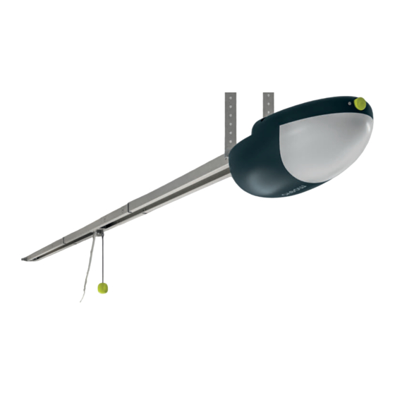
Operator for
garage doors
MD432KM
EN
Installation and use instruc-
tions and warning
IT
Istruzioni ed avvertenze per
l'installazione e l'uso
PL
Instrukcje instalacji i
użytkowania i ostrzeżenia
Code: IS0876A00MM – 09-09-2022
FR
Instructions et avertisse-
ments pour l'installation et
l'utilisation
PT
Instruções e advertências
de instalação e uso
Publicité

Manuels Connexes pour moovo MD432KM


Sommaire des Matières pour moovo MD432KM
- Page 1 Operator for garage doors MD432KM Installation and use instruc- Instructions et avertisse- tions and warning ments pour l’installation et l’utilisation Istruzioni ed avvertenze per l’installazione e l’uso Instruções e advertências de instalação e uso Instrukcje instalacji i użytkowania i ostrzeżenia...
- Page 3 CONTENTS GENERAL SAFETY WARNINGS AND PRECAUTIONS LED INDICATIONS STEP 1 STEP 11 11.1 Input LED status indications ..... 21 KNOWLEDGE OF THE PRODUCT AND PREPARATION 11.2 Error LED .
- Page 4 – should liquids penetrate parts of the automation components, disconnect the power supply immediately and contact the Moovo Technical Assistance Service. Using the automation in these conditions constitutes a potential hazard.
- Page 5 – the system’s power supply network must include a disconnection – permanently attach the trapping hazard warning labels in a highly device (not supplied) with a contact opening gap permitting complete visible location or near the fixed control devices (if present). –...
- Page 6 [b] - 3-piece guide for carriage + joining brackets improper and is strictly forbidden! [c] - omega-shaped fastening bracket This product (MD432KM) comprises an electromechanical gearmotor [d] - gearmotor ceiling-mounting brackets [e] - guide wall-mounting bracket with a 24 VDC motor and a three-piece guide with belt transmission.
- Page 7 Up-and-over door Height: Surface Height: Surface • When automating a projecting up-and-over door, ensure that MD432KM 2.4 m area: 10 m 2.4 m area: 8.5 m movement does not obstruct public roads or pavements. • Ensure that the mechanical structure of the door is suitable for being Table 2: limits in relation to the door height automated and complies with local regulations.
- Page 8 Note - The shape of the door and weather conditions, such as the STEP 4 presence of strong winds, can reduce the above maximum values. STEP 4 In these cases, it is important to measure the force required to move 4.1 PRELIMINARY SET-UP the door in the worst conditions and compare it with the technical specifications of the gearmotor.
- Page 10 Technical specifications of electrical cables (note 1) Devices Terminals Function Type of cable Maximum admissible length TX 2 x 0.25 mm cables 20 m (note 2) Safety photocells 3 - 5 PHOTO input RX 3 x 0.25 mm cables 20 m (note 2) Control button 3 - 4 STEP-BY-STEP input...
- Page 11 INSTALLATION: COMPONENT ASSEMBLY AND CONNECTION STEP 5 06. slide the head (G) to the end of the guide STEP 5 07. turn the guide upside-down and lock the head (G) using the screw provided (“Fig. 14”) 5.1 INSTALLING THE AUTOMATION COMPONENTS WARNINGS •...
- Page 12 11. from the opening side of the door, position the wall mounting 13. mount the door mounting bracket (K) on the drawbar (L) bracket (J) on the guide and lock it by inserting the pin and cotter 14. insert the relevant pin (M) into the drawbar and lock it in place with pin (“Fig.
- Page 13 19. measure the desired distance “B”, which will define how far the 24. using a ladder, lift the gearmotor until the brackets rest against the gearmotor will be from the ceiling, and cut the two ceiling-mounted drilled holes brackets (Q) to size 25.
- Page 14 29. slide the motor carriage until the door mounting bracket (K) on the 5.2 MANUALLY UNLOCKING AND LOCKING THE upper edge of the door lies exactly perpendicular to the guide (A) GEARMOTOR 30. fasten the bracket (K) using the screws and rivets suited to the door material and the force required to move the door itself The gearmotor is equipped with a mechanical unlocking device that (“Fig.
- Page 15 The MD432KM must be connected to the power supply by a qualified electrician. To test the MD432KM, plug it into a power outlet using an extension if necessary (Fig. “37”). Fig. “35”” 03. Pass the cables through the holes [S] (...
- Page 16 6.3 DESCRIPTION OF THE ELECTRICAL CONNECTIONS Table 3 Terminals Function Description Below is a brief description of the electrical connections (“Table 3” - Fig. “38”” ); for further information, read “STEP 14” (“Devices that can Control output through the transmitter 1 - 2 OUT1 button.
- Page 17 SETTING THE CONTROL UNIT STEP 7 If the “check” dip-switch is set to OFF, the safety devices STEP 7 connected to the “Phototest” terminal [3] are constantly powered. 7.1 DIP-SWITCH ADJUSTMENT DIP4 “FUNCTION”: If the dip-switch is set to OFF, the safety devices connected to terminal “S2 Photo”...
- Page 18 PROGRAMMING THE TRANSMITTER STEP 8 8.3 PROGRAMMING THE BUTTON CONNECTED TO THE STEP 8 OUT1 OUTPUT This procedure can be adopted to programme the remote control button connected to the “OUT1” output (terminals 1-2). ACTION RESULT PRESS THE RADIO BUT- “radio”...
- Page 19 8.6 DELETING A SINGLE TRANSMITTER This operation deletes a single transmitter from the memory. ACTION RESULT PRESS THE RADIO IN A PREVIOUSLY BUTTON FOR 4 SECONDS The red “radio” LED MEMORISED TRANSMITTER, AND RELEASE IT WHEN lights up (if not, consult PRESS AND HOLD KEYS T1 THE RADIO LED STARTS paragraph 14.3.1)
- Page 20 (for example Fig. 1), wiring diagram (for example Fig. 31), risk analysis and relative solutions adopted, manufacturer conformity declaration for all devices used. For MD432KM use Annex 1 “EC declaration of conformity of the components...
- Page 21 STEP 11 RED RADIO LED: STEP 11 - flashes when a command is received from a Moovo radio transmitter - lit steady when the control unit is in a radio programming menu - off when the control unit is in stand-by mode...
- Page 22 RESET PROCEDURE STEP 12 This reset does not delete the memorised radio transmitters STEP 12 (see “STEP 8” for the management of radio transmitters). The reset procedure deletes the door path parameters (“STEP 9”) and all the advanced functions (“STEP 13”). It can be carried out in the event of programming errors and restores the control unit factory set- tings.
- Page 23 When multiple devices are connected to this contact, they must be connected in series. If multiple pairs of photocells are connected, the RX and TX units of the safety group must be installed in a criss-cross pattern. “S1 Edge” SAFETY DEVICES FOR THE OPENING/CLOSING PHASES.
- Page 24 ADVANCED PROCEDURE STEP 14 Backjump levels: 0 / 500 ms / 700 ms / 1 s / 1.5 s / 2 s. STEP 14 When the series is made up of a flash of the Set LED, the back- The control unit has other special characteristics that are not nec- jump value is zero (no reversal of movement at the end of the essary for most standard installations.
- Page 25 14.2 SELECTING THE TYPE OF DEVICES CONNECTED TO The control unit constantly verifies the integrity of the edge by “S1 EDGE” measuring the resistance between the two dedicated terminals. By default = “S1 Edge”set for devices with normally closed To perform the check on the safety devices, the contact (terminal 9) connected edges must be of the resistive type with 8.2 This procedure allows for setting the “S1 Edge”...
- Page 26 TROUBLESHOOTING STEP 15 STEP 15 Problems Symptoms/causes Solution The control unit LEDs No power to the control unit Check the mains voltage – see paragraph “6.1 are switched off Connecting the devices included in the system” / “6.2 When connecting the power supply”. The fuses have blown.
- Page 27 The devices of the MD432KM automation do not require spe- If other devices are present, follow the instructions in the relative cial maintenance. However a check should be performed at least maintenance schedule.
- Page 28 STEP 18 MD432KM is manufactured by Moovo. In order to improve its products, Moovo reserves the right to modify their technical specifica- tions at any time without prior notice. In any case, the manufacturer guarantees their functionality and suitability for their intended use.
- Page 29 USER GUIDE (to be handed to the end user) STEP 19 STEP 19 To unlock the device: This user guide should be stored and handed to all users of 01. pull the unlocking cord (A) (“Fig. “46””) the automation. 19.1 WARNINGS •...
- Page 30 19.4 REPLACING THE TRANSMITTER BATTERY 04. Then, holding the transmitter with the keys facing upwards, put the battery cover back in place and ensure that the “tab” shown in grey in the figure is above the battery, as shown in the figure below. The appliance must be disconnected from the power supply when removing the batteries.
- Page 31 19.6 MAINTENANCE SCHEDULE 19.7 MAINTENANCE REGISTER Warning! – All maintenance work on this system must be carried Important – Before passing this maintenance register on to the owner out by qualified technical personnel, in full compliance with the of the automation, make sure that all the necessary information has been safety standards provided for by the laws in force and the safety filled in.
- Page 32 Description of intervention performed Signature of Signature of Date Technician Owner (describe the checks, adjustments, repairs, modifications, etc.)
- Page 33 Declaration of conformity EU Declaration of Conformity (N. 793/MD432) and declaration of incorporation of “partly completed machinery” Rev: 0 Language: English Manufacturer’s Name: Nice S.p.A. Address: Via Callalta n°1, 31046 Oderzo (TV) Italy Authorized Person to constitute the technical documentation: Nice S.p.A.
- Page 34 EC DECLARATION OF CONFORMITY In conformity to Directive 98/37/EC, ANNEX II, part A (EC declaration of conformity for machinery) The undersigned / company: (name or company name of the subject responsible for commissioning the power-operated door) (address) Hereby declares under his/her/its sole responsibility that: The automation: o power-operated sectional door o power-operated up-and-over door...
- Page 37 INDICE AVVERTENZE E PRECAUZIONI GENERALI PER LA INDICAZIONI LED SICUREZZA PASSO 11 PASSO 1 11.1 Indicazione led di stato degli ingressi ....21 11.2 Led errore .
- Page 38 Non procedere con l’installazione se si hanno dubbi di qualunque na- presi) le cui capacità fisiche, sensoriali o mentali siano ridotte, oppure tura e richiedere eventuali chiarimenti al Servizio Assistenza Moovo. con mancanza di esperienza o di conoscenza. Se questa è la prima volta che vi apprestate a realizzare un’automazio- Considerando le situazioni di rischio che possono verificarsi du- ne per portoni da garage (“sezionali”...
- Page 39 – nella rete di alimentazione dell’impianto prevedere un dispositivo di – fissare in modo permanente le etichette di avvertenza contro l’in- disconnessione (non in dotazione) con una distanza di apertura dei trappolamento in un punto molto visibile o in prossimità di eventuali contatti che consenta la disconnessione completa nelle condizioni dispositivi di comando fissi.
- Page 40 [e] - staffa per fissare la guida alla parete [f] - fermi meccanici per l’arresto del carrello Il presente prodotto (MD432KM) composto da un motoriduttore elet- [g] - sistema di sblocco con minuteria metallica (viti, rondelle, ecc.)* tromeccanico con un motore in corrente continua a 24V, una guida [h] - staffe ad innesto rapido per fissaggio a soffitto SRA1 in tre pezzi con trasmissione a cinghia.
- Page 41 Altezza: Superficie: Altezza: Superficie: pubblici. MD432KM 2.4 m 10 m 2.4 m 8.5 m • Verificare che la struttura meccanica del portone sia adatta ad essere automatizzata e conforme alle norme vigenti sul territorio.
- Page 42 Nota – La forma del portone e le condizioni climatiche come ad esem- PASSO 4 pio la presenza di vento forte, possono ridurre i valori massimi riportati. PASSO 4 In questi casi è importante misurare la forza necessaria a muovere il 4.1 LAVORI PRELIMINARI DI PREDISPOSIZIONE portone nella peggiore delle condizioni e confrontarla con i dati riportati nelle caratteristiche tecniche del motoriduttore.
- Page 44 Caratteristiche tecniche dei cavi elettrici (nota 1) Dispositivi Morsetti Funzione Tipo di cavo Lunghezza massima consentita Fotocellule di TX Cavo 2 x 0,25 mm2 20 m (nota 2) 3 - 5 Ingresso FOTO sicurezza RX Cavo 3 x 0,25 mm2 20 m (nota 2) Pulsante di 3 - 4...
- Page 45 INSTALLAZIONE: MONTAGGIO E COLLEGAMENTO DEI COMPONENTI PASSO 5 06. far scorrere la testa (G) fino all’estremità della guida PASSO 5 07. capovolgere la guida e bloccare la testa (G) utilizzando le viti fornite a corredo (“Figura 14”) 5.1 INSTALLARE I COMPONENTI DELL’AUTOMAZIONE AVVERTENZE •...
- Page 46 11. dal lato di apertura del portone, posizionare la staffa a muro (J) sul- 13. montare la staffa di attacco portone (K) sull’asta di traino (L) la guida e bloccarla inserendo il perno e la coppiglia (“Figura 17”) 14. inserire l’apposito perno (M) sull’asta e bloccarlo con la coppiglia (N) (“Figura19”) SOLO PER I PORTONI BASCULANTI Se il portone da automatizzare è...
- Page 47 19. rilevare la quota desiderata “B” che rappresenta la distanza che 24. utilizzando una scala, sollevare il motoriduttore fino a fare appog- dovrà avere il motoriduttore dal soffitto e tagliare a misura le due giare le staffe sui fori appena fatti staffe a soffitto (Q) 25.
- Page 48 29. far scorrere il carrello motore fino a portare la staffa di attacco 5.2 SBLOCCARE E BLOCCARE MANUALMENTE IL portone (K) sul bordo superiore dello stesso, esattamente perpen- MOTORIDUTTORE dicolare alla guida (A) 30. fissare la staffa (K) utilizzando viti o rivetti adeguati al materiale del Il motoriduttore è...
- Page 49 MD432KM deve essere connesso all’alimentazione da un elettrici- sta qualificato. Per testare MD432KM, inserire la spina in una presa usando una pro- lunga se necessario (fig. 37). fig. "35" 03. Passare i cavi tramite il foro [S] (...
- Page 50 6.3 DESCRIZIONE DEI COLLEGAMENTI ELETTRICI Tabella 3 Morsetti Funzione Descrizione Di seguito una breve descrizione delle connessioni elettriche (“Tabella 3” - fig. "38" ); per maggiori informazioni, leggere il “PASSO 14” (“Di- Uscita di comando tramite pulsante spositivi collegabili alla centrale”). del trasmettitore.
- Page 51 IMPOSTAZIONE DELLA CENTRALE PASSO 7 Se il dip-switch “check” viene messo in OFF, i dispositivi di sicu- PASSO 7 rezza collegati al morsetto “Phototest” [3] vengono costantemen- te alimentati. 7.1 REGOLAZIONE DEI DIP-SWITCHES DIP4 “FUNCTION”: Se il dip-switch è messo su OFF, i disposi- tivi di sicurezza collegati al morsetto “S2 Photo”...
- Page 52 PROGRAMMAZIONE DEL TRASMETTITORE PASSO 8 8.3 PROGRAMMAZIONE DEL PULSANTE COLLEGATO PASSO 8 ALL’USCITA OUT1 Questa procedura permette di programmare il tasto del radiocomando collegato all’uscita “OUT1” (morsetti 1-2). AZIONE RISULTATO rosso PREMI IL PULSANTE RA- "radio" si accende in DIO PER 1 SECONDO modalità...
- Page 53 8.6 CANCELLAZIONE DI UN SINGOLO TRASMETTITORE Questa operazione elimina un singolo trasmettitore dalla memoria. AZIONE RISULTATO PREMERE IL PULSANTE IN UN TRASMETTITORE Il LED rosso "radio" RADIO PER 4 SECONDI E GIA’ MEMORIZZATO TENERE lampeggia (in caso RILASCIARE QUANDO IL PREMUTI I contrario, consultare il LED RADIO INCOMINCIA A...
- Page 54 (ad esempio figura 1), schema dei colle- gamenti elettrici (ad esempio fig. 31), analisi dei rischi e relative soluzioni adottate, dichiarazione di conformità del fabbricante di tutti i dispositivi utilizzati. Per MD432KM utilizzare l’allegato 1 “Dichiarazione CE di confor-...
- Page 55 MD432KM”. proprietario sui pericoli ed i rischi ancora presenti. 2 Apporre sul portone una targhetta contenente almeno i seguenti dati: tipo 8 Fissare in maniera permanente sul portone una etichetta o targa con di automazione, nome e indirizzo del costruttore (responsabile della “messa questa immagine (altezza minima 60mm) con scritto ATTENZIONE - in servizio”), numero di matricola, anno di costruzione e marchio “CE”.
- Page 56 PROCEDURA DI RESET PASSO 12 Questo reset non cancella i trasmettitori radio memorizzati PASSO 12 (vedi “PASSO 8” per la gestione dei trasmettitori radio). La procedura di reset cancella i parametri del percorso della porta (“PASSO 9”) e tutte le funzioni avanzate (“PASSO 13”). Può essere eseguita in caso di errori di programmazione e riporta la centrale alle impostazioni di fabbrica.
- Page 57 Quando si collegano più dispositivi a questo contatto, devo- no essere collegati in serie. Se si collegano più coppie di fotocellule, le unità RX e TX del gruppo di sicurezza devono essere installate incrociate. “S1 Edge” DISPOSITIVI DI SICUREZZA IN FASE DI APERTURA/ CHIUSURA.
- Page 58 PROCEDURA AVANZATA PASSO 14 Livelli di backjump: 0 / 500ms / 700ms / 1Sec / 1,5 Sec / 2Sec. PASSO 14 Quando la serie è costituita da un lampeggio del led Set, il valore La centrale dispone di ulteriori caratteristiche speciali non neces- di backjump è...
- Page 59 14.2 SELEZIONE DEL TIPO DI DISPOSITIVI COLLEGATI A La centrale verifica costantemente l’integrità della costa misuran- “S1 EDGE” do la resistenza tra i due terminali dedicati. Di fabbrica = “S1 Edge” impostato per dispositivi con con- Per effettuare il controllo sui dispositivi di sicurezza, tatto normalmente chiuso (morsetto 9) le coste collegate devono essere di tipo resistivo con 8.2 Questa procedura consente di impostare l’uscita “S1 Edge”...
- Page 60 RISOLUZIONE DEI PROBLEMI PASSO 15 PASSO 15 Problemi Sintomi/cause Soluzione I LED della centrale Nessuna alimentazione alla centrale Controllare la tensione di rete – vedere il paragrafo “6.1 sono spenti Collegamento dei dispositivi previsti nell’impianto” / “6.2 All’allacciamento dell’alimentazione”. I fusibili sono saltati. È necessario Sostituire i fusibili.
- Page 61 “19.3 Interventi di manutenzione concessi all’u- vigenti. tilizzatore”. I dispositivi per l’automazione MD432KM non necessitano di Se sono presenti altri dispositivi seguire quanto previsto nel rispettivo piano manutenzione. SMALTIMENTO DEL PRODOTTO PASSO 17 “raccolta separata”...
- Page 62 200 m all’esterno; 35 m all’interno di edifici ( Tutti i radiocomandi possono essere soggetti ad interferenze che ne possono alterare le prestazioni. Nei casi di queste interferenze, Moovo non può offrire nessuna garanzia circa la reale portata dei propri dispositivi.
- Page 63 GUIDA ALL’USO (da consegnare all’utilizzatore finale) PASSO 19 PASSO 19 Per effettuare lo sblocco: Si consiglia di conservare questa guida all'uso e consegnar- 01. tirare il cordino di sblocco (A) (“Figura “46””) la a tutti gli utilizzatori dell’automatismo. 19.1 AVVERTENZE •...
- Page 64 19.4 SOSTITUZIONE PILA DEL TRASMETTITORE 04. Quindi, tenendo il trasmettitore con i tasti rivolti verso l’alto, rein- serire il copri pila nella sua sede iniziale facendo in modo che la “lamella” rappresentata in colore grigio stia sopra la pila, come L’apparecchio deve essere scollegato dall’alimentazione mostrato nella figura di seguito.
- Page 65 19.6 PIANO DI MANUTENZIONE 19.7 REGISTRO DI MANUTENZIONE Attenzione! – La manutenzione dell’impianto deve essere effettua- Importante – Questo registro di manutenzione deve essere consegnato ta da personale tecnico e qualificato, nel pieno rispetto delle nor- al proprietario dell’automazione dopo averlo compilato nelle parti richie- me per la sicurezza previste dalle leggi vigenti e delle prescrizioni ste.
- Page 66 Descrizione dell’intervento effettuato Firma del Firma del Data Tecnico Proprietario (descrivere le verifiche, le regolazioni, le riparazioni, le modifiche ecc.)
- Page 67 Dichiarazioni di conformità Dichiarazione di Conformità UE (N.793/MD432) e dichiarazione di incorporazione di “quasi macchina” Rev: 0 Lingua: Italiano Nome Produttore: Nice S.p.A. Indirizzo: Via Callalta n°1, 31046 Oderzo (TV) Italy Persona autorizzata a costituire la documentazione tecnica: Nice S.p.A. Indirizzo: Via Callalta n°1, 31046 Oderzo (TV) Italy Tipo di prodotto:...
- Page 68 DICHIARAZIONE CE DI CONFORMITÀ Secondo la direttiva 98/37/CE ALLEGATO II parte A (dichiarazione CE di conformità per le macchine) Il sottoscritto / ditta: (nome o ragione sociale di chi ha messo in servizio il portone motorizzato) (indirizzo) Dichiara sotto la propria responsabilià che: L’automazione: o portone sezionale motorizzato o portone basculante motorizzato...
- Page 71 SPIS TREŚCI OGÓLNE OSTRZEŻENIA I ZALECENIA DOTYCZĄCE WSKAZANIA DIOD LED BEZPIECZEŃSTWA KROK 11 KROK 1 11.1 Sygnalizacja stanu wejść diodami LED ....21 11.2 Dioda LED błędu ........21 ZNAJOMOŚĆ...
- Page 72 – produkt nie jest przeznaczony do obsługi przez osoby (w tym W przypadku jakichkolwiek wątpliwości nie należy przystępować do dzieci) o ograniczonych zdolnościach fizycznych, zmysłowych montażu i zwrócić się o wyjaśnienia do Serwisu Technicznego Moovo. bądź umysłowych lub przez osoby nieposiadające odpowiedniego doświadczenia i wiedzy.
- Page 73 – w sieci zasilającej system zapewnić urządzenie odłączające – umieścić na stałe etykiety ostrzegające przed uwięzieniem w dobrze (niedostarczone) o odległości rozwarcia styków umożliwiającej widocznym miejscu lub w pobliżu ewentualnych stałych urządzeń całkowite odłączenie warunkach dyktowanych kategorią sterujących. – umieścić na stałe etykietę dotyczącą ręcznego zwalniania (obsługa przepięciową...
- Page 74 [b] - 3-częściowa prowadnica wózka + wsporniki łączące [c] - uchwyt mocujący omega [d] - uchwyty do mocowania motoreduktora do sufitu Niniejszy produkt (MD432KM) składa się z motoreduktora elektrome- [e] - uchwyt do mocowania prowadnicy do ściany chanicznego z silnikiem prądu stałego 24V, trzyczęściowej prowadnicy [f] - ograniczniki mechaniczne do zatrzymania wózka...
- Page 75 • W przypadku automatyzacji bramy uchylnej sprawdzić, czy jej ruch Wysokość: Powierzch- Wysokość: Powierzch- nie zajmuje przestrzeni dróg lub chodników publicznych. MD432KM 2,4 m nia: 10 m 2,4 m nia: 8,5 m • Sprawdzić, czy konstrukcja mechaniczna bramy nadaje się do automa- tyzacji i czy jest zgodna z obowiązującymi na danym obszarze przepisami.
- Page 76 Uwagi – Kształt bramy oraz warunki klimatyczne, np. obecność silnych KROK 4 wiatrów, mogą dodatkowo zmniejszyć wartości maksymalne. W takim KROK 4 przypadku ważne jest określenie siły potrzebnej do przesunięcia bramy 4.1 WSTĘPNE PRACE PRZYGOTOWAWCZE w najgorszych warunkach i porównanie jej z wartościami podanymi w parametrach technicznych motoreduktora.
- Page 78 Dane techniczne przewodów elektrycznych (uwaga 1) Urządzenia Zaciski Funkcja Typ przewodu Maksymalna dozwolona długość TX Przewód 2 x 0,25 Fotokomórki 20 m (uwaga 2) 3 - 5 Wejście FOTO bezpieczeństwa RX Przewód 3 x 0,25 20 m (uwaga 2) Przycisk sterujący 3 - 4 Wejście KROK PO KROKU Przewód 2 x 0,25 mm2...
- Page 79 INSTALACJA: MONTAŻ I PODŁĄCZENIE ELEMENTÓW KROK 5 06. przesunąć głowicę (G) do końca prowadnicy KROK 5 07. odwrócić prowadnicę i zablokować głowicę (G) przy użyciu dołączonych śrub („Rysunek 14”) 5.1 INSTALACJA ELEMENTÓW NAPĘDU OSTRZEŻENIA • Nieprawidłowy montaż może spowodować poważne obrażenia osoby wykonującej prace oraz osób, które będą...
- Page 80 11. od strony otwarcia bramy, umieścić uchwyt do mocowania na 13. zamontować uchwyt zaczepu bramy (K) na drążku ciągnącym (L) ścianie (J) na prowadnicy i zablokować go, wsuwając sworzeń i 14. wsunąć sworzeń (M) w drążek i zabezpieczyć go za pomocą zawleczkę...
- Page 81 19. określić żądany wymiar „B”, stanowiący odległość motoreduktora 24. wykorzystując drabinę, podnieść motoreduktor aż do oparcia od sufitu, i przyciąć dwa uchwyty sufitowe (Q) na wymiar uchwytów na nawierconych otworach 20. przymocować przy użyciu dwóch śrub uchwyty do sufitu (Q), 25.
- Page 82 29. przesunąć wózek silnika aż do przeniesienia uchwytu zaczepu 5.2 RĘCZNE BLOKOWANIE I ODBLOKOWYWANIE bramy (K) na górną krawędź bramy, dokładnie prostopadle do MOTOREDUKTORA prowadnicy (A) 30. przymocować uchwyt (K) stosując śruby lub nity odpowiednie Motoreduktor jest wyposażony system mechanicznego do materiału, z którego wykonana jest brama, i siły koniecznej do wysprzęglania, który umożliwia ręczne otwieranie i zamykanie bramy.
- Page 83 ścisłej zgodności z obowiązującymi przepisami, regulacjami i normami. MD432KM musi zostać podłączone do zasilania przez wykwalifikowanego elektryka. Aby przetestować MD432KM, włożyć wtyczkę do gniazda, używając w razie potrzeby przedłużacza (rys. „37”). rys. „„35”” 03. Przeprowadzić przewody przez otwór [S] (...
- Page 84 6.3 OPIS POŁĄCZEŃ ELEKTRYCZNYCH Tabela 3 Zaciski Funkcja Opis Poniżej zamieszczono krótki opis połączeń elektrycznych („Tabela 3” - rys. „„38”” ); więcej informacji można znaleźć „KROK 14” Wyjście sterowania za pomocą przycisku nadajnika. Beznapięciowy („Urządzenia, które można podłączyć do centrali”). 1 - 2 OUT1 styk przekaźnikowy dla obciążeń...
- Page 85 USTAWIENIA CENTRALI KROK 7 pomocą potencjometru „pause” (Zob. punkt „7.2 Regulacja KROK 7 potencjometrów”). Jeśli przełącznik DIP „auto” zostaje ustawiony na OFF, funkcja automatycznego zamykania jest 7.1 REGULACJA PRZEŁĄCZNIKÓW DIP wyłączona. Aby zamknąć bramę, należy wydać odpowiednie polecenie (przewodowo lub przez nadajnik radiowy). DIP3 „CHECK”: Jeśli przełącznik DIP jest ustawiony na ON, urządzenia zabezpieczające podłączone do zacisku „Phototest”...
- Page 86 PROGRAMOWANIE NADAJNIKA KROK 8 8.3 PROGRAMOWANIE PRZYCISKU POŁĄCZONEGO Z KROK 8 WYJŚCIEM OUT1 Ta procedura umożliwia zaprogramowanie przycisku pilota radiowego połączonego z wyjściem „OUT1” (zaciski 1-2). DZIAŁANIE REZULTAT Czerwona dioda LED WCISNĄĆ PRZYCISK RA- „radio” zapala się DIO NA 1 SEKUNDĘ światłem ciągłym START Czerwona dioda LED...
- Page 87 8.6 USUWANIE POJEDYNCZEGO NADAJNIKA Ta operacja powoduje usunięcie z pamięci pojedynczego nadajnika. DZIAŁANIE REZULTAT WCISNĄĆ PRZYCISK RADIO Czerwona dioda LED NA UPRZEDNIO NA 4 SEKUNDY I ZWOLNIĆ, „radio” miga (jeśli tak WCZYTANYM NADAJNIKU GDY DIODA LED RADIO nie jest, zob. punkt PRZYTRZYMAĆ...
- Page 88 DZIAŁANIE REZULTAT Jeśli potencjometr „Force” zostanie zmodyfikowany, BRAMA WYKONUJE Żółta dioda LED „set” należy przeprogramować ruch napędu. RUCH CAŁKOWITEGO pozostaje zapalona ZAMKNIĘCIA światłem ciągłym Czerwona dioda „Error” miga podczas automatyzowanego ruchu, gdy wykryty zostanie punkt BRAMA WYKONUJE Żółta dioda LED „set” RUCH CAŁKOWITEGO pozostaje zapalona obciążenia mechanicznego (odpowiada to zwiększonemu...
- Page 89 7 Przed oddaniem napędu do eksploatacji należy odpowiednio deklarację zgodności producenta wszystkich stosowanych urządzeń. poinformować właściciela o wciąż występujących zagrożeniach i ryzyku. W przypadku MD432KM użyć załącznika 1 „Deklaracja zgodności WE 8 Przymocować na stałe na bramie etykietkę lub tabliczkę z następującym elementów składowych MD432KM”.
- Page 90 PROCEDURA RESETU KROK 12 Ten reset nie powoduje usunięcia zapisanych nadajników ra- KROK 12 diowych (informacje na temat zarządzania nadajnikami radiowymi Procedura resetu usuwa parametry trasy bramy („KROK 9”) i wszyst- można znaleźć w „KROK 8”). kie funkcje zaawansowane („KROK 13”). Może zostać przeprowadzo- na w przypadku błędów w programowaniu i przywraca centralę...
- Page 91 W przypadku podłączenia kilku urządzeń do tego styku, muszą być one połączone szeregowo. Jeśli podłączonych jest kilka par fotokomórek, jednostki RX i TX zespołu bezpieczeństwa muszą być zainstalowane krzyżowo. „S1 Edge” URZĄDZENIA ZABEZPIECZAJĄCE PODCZAS OTWIERANIA/ZAMYKANIA. Możliwe jest podłączenie urządzeń (np. fotokomórek lub listew krawędziowych) ze stykami normalnie zamkniętymi (NC) lub listwami 3 4 5 rezystancyjnymi 8k2 do wejścia „S1 Edge”...
- Page 92 PROCEDURA ZAAWANSOWANA KROK 14 Poziomy backjump: 0 / 500 ms / 700 ms / 1 s / 1,5 s / 2 s. KROK 14 Gdy na serię składa się z jednego mignięcia diody led Set, Centrala posiada dodatkowe funkcje specjalne, które nie są wartość...
- Page 93 14.2 WYBÓR RODZAJU URZĄDZEŃ PODŁĄCZONYCH DO Centrala stale monitoruje stan listwy poprzez pomiar rezystancji „S1 EDGE” pomiędzy dwoma dedykowanymi zaciskami. Ustawienie fabryczne = „S1 Edge” ustawione na urządzenia Aby przeprowadzić kontrolę urządzeń ze stykiem normalnie zamkniętym (zacisk 9) zabezpieczających, podłączone listwy krawędziowe Procedura ta pozwala na ustawienie wyjścia „S1 Edge”...
- Page 94 ROZWIĄZYWANIE PROBLEMÓW KROK 15 KROK 15 Usterki Objawy/przyczyny Środki zaradcze Diody LED centrali są Brak zasilania centrali Sprawdzić napięcie sieciowe – zob.punkt „6.1 wyłączone Podłączenie urządzeń będących częścią systemu” / „6.2 Podłączenie zasilania”. Przepaliły się bezpieczniki. Przed Wymienić bezpieczniki. W przypadku ponownego dotknięciem bezpieczników należy przepalenia bezpieczników należy sprawdzić, czy nie doszło odłączyć...
- Page 95 „19.3 Prace konserwacyjne, które może wykonywać instrukcji oraz w zgodzie z obowiązującymi przepisami i użytkownik”. normami. W przypadku występowania innych, dodatkowych urządzeń, Urządzenia automatyki MD432KM nie wymagają specjalnych należy przestrzegać planu konserwacji przedstawionego w ich czynności konserwacyjnych; należy jednak sprawdzać okresowo instrukcjach obsługi. UTYLIZACJA URZĄDZENIA KROK 17 W celu usunięcia produktu należy zatem przeprowadzić...
- Page 96 KROK 18 KROK 18 MD432KM jest wyprodukowany przez Moovo. Moovo zastrzega sobie prawo do zmiany parametrów technicznych swych produktów w dowolnej chwili i bez uprzedzenia, gwarantując jednakże, że będą one dalej pełnić swe funkcje zgodnie z ich przewidzianym zasto- sowaniem. Uwaga: wszystkie parametry techniczne odnoszą się do temperatury 20°C.
- Page 97 INSTRUKCJA OBSŁUGI (do przekazania użytkownikowi końcowemu) KROK 19 KROK 19 W celu wysprzęglenia: Zalecamy zachować instrukcję i przekazywać ją wszystkim 01. pociągnąć linkę wysprzęglającą (A) („Rysunek „46””) użytkownikom urządzenia. 19.1 OSTRZEŻENIA • Nadzorować bramę podczas jej ruchu i zachować bezpieczną odległość do momentu całkowitego otwarcia lub zamknięcia bramy.
- Page 98 19.4 WYMIANA BATERII W NADAJNIKU 04. Następnie, trzymając nadajnik z przyciskami skierowanymi do góry, ponownie włożyć pokrywę baterii w jej pierwotne miejsce, tak aby „blaszka”, zaznaczona kolorem szarym, znalazła się nad Podczas wyjmowania baterii urządzenie musi być odłączone baterią, jak pokazano na rysunku poniżej. od zasilania.
- Page 99 19.6 PLAN KONSERWACJI 19.7 DZIENNIK KONSERWACJI Uwaga! – Konserwacja systemu musi być przeprowadzana przez Ważne – Niniejszy dziennik konserwacji należy przekazać, po wypełnieniu wykwalifikowany personel techniczny, w poszanowaniu obowią- wymaganych części, właścicielowi napędu. zujących przepisów bezpieczeństwa i zaleceń dotyczących bez- pieczeństwa zamieszczonych w KROKU 1 - „Ogólne ostrzeżenia W dzienniku należy zapisywać...
- Page 100 Opis wykonanej pracy Podpis Podpis Data Technika Właściciela (opisać kontrole, regulacje, naprawy, modyfikacje itp.)
- Page 101 Deklaracje zgodności Deklaracja Zgodności UE (N.793/MD432) i deklaracja włączenia „maszyny nieukończonej” Wer.: 0 Język: Polski Nazwa Producenta: Nice S.p.A. Adres: Via Callalta n°1, 31046 Oderzo (TV) Italy Osoba upoważniona do sporządzenia dokumentacji technicznej: Nice S.p.A. Adres: Via Callalta n°1, 31046 Oderzo (TV) Italy Typ produktu: Wstępnie zmontowany motoreduktor 24Vdc z wbudowaną...
- Page 102 DEKLARACJA ZGODNOŚCI WE Zgodnie z dyrektywą 98/37/WE, ZAŁĄCZNIK II, część A (deklaracja zgodności WE dla maszyn) Niżej podpisany / firma: (nazwisko lub nazwa firmy, która oddała do użytku bramę z napędem) (adres) Oświadcza na własną odpowiedzialność, że: System automatyki: o brama segmentowa z napędem o brama uchylna z napędem Nr seryjny: Rok produkcji:...
- Page 105 TABLE DES MATIÈRES CONSIGNES ET PRÉCAUTIONS GÉNÉRALES DE INDICATIONS LED SÉCURITÉ PHASE 11 PHASE 1 11.1 Indication LED de l’état des entrées ....21 11.2 LED error .
- Page 106 – si des substances liquides pénètrent à l’intérieur de certains composants de l’automatisme, déconnecter immédiatement l’alimentation électrique et s’adresser au Service après-vente Moovo. L’utilisation de l’automatisme dans ces conditions peut créer symboles des situations dangereuses. indiquent des arguments qui peuvent être une source potentielle –...
- Page 107 – s’assurer que les éléments de commande sont bien à l’écart des – fixer de manière permanente les étiquettes d’avertissement contre organes en mouvement tout en restant directement visibles. les risques de piégeage dans un endroit bien en vue ou à proximité –...
- Page 108 PHASE 3 doit être considérée comme impropre et interdite ! [d] - pattes de fixation de l’opérateur au plafond Ce produit (MD432KM) est composé d’un opérateur électromécanique [e] - patte de fixation du rail au mur [f] - butée mécanique pour l’arrêt du chariot avec un moteur en courant continu à...
- Page 109 Porte basculante Hauteur : Surface : Hauteur : Surface : • En cas d’automatisation d’une porte basculante débordante, vérifier MD432KM 2,4 m 10 m 2,4 m 8,5 m que son mouvement n’encombre ni la rue ni le trottoir. • Vérifier que la structure mécanique de la porte de garage est adaptée Tableau 2 : limites relatives à...
- Page 110 Remarque – La forme de la porte de garage et les conditions PHASE 4 climatiques, telles que la présence de vent fort, peuvent réduire les PHASE 4 valeurs maximales indiquées. Dans ce cas, il est important mesurer 4.1 TRAVAUX PRÉALABLES la force nécessaire pour manœuvrer la porte de garage dans la pire des conditions et de la comparer aux données indiquées dans les caractéristiques techniques de l’opérateur.
- Page 112 Caractéristiques techniques des câbles électriques (remarque 1) Dispositifs Bornes Fonction Type de câble Longueur maximale autorisée Photocellules de Émetteur Câble 2 x 0,25 mm 20 m (remarque 2) 3 - 5 Entrée PHOTO sécurité Récepteur Câble 3 x 0,25 mm 20 m (remarque 2) Touche de 3 - 4...
- Page 113 INSTALLATION : MONTAGE ET CONNEXIONS DES COMPOSANTS PHASE 5 06. faire glisser la tête (G) jusqu’à l’extrémité du rail PHASE 5 07. retourner le rail et bloquer la tête (G) à l’aide des vis fournies (« Figure 14 ») 5.1 INSTALLER LES COMPOSANTS DE L’AUTOMATISME RECOMMANDATIONS •...
- Page 114 11. du côté de l’ouverture de la porte de garage, positionner l’étrier 13. monter l’étrier de fixation de la porte (K) sur la tige d’entraînement mural (J) sur le rail et le bloquer en insérant le pivot et la goupille («...
- Page 115 19. déterminer la cote souhaitée « B » qui représente la distance à 24. à l’aide d’une échelle, soulever l’opérateur jusqu’à ce que les laquelle l’opérateur doit se trouver par rapport au plafond et étriers soient contre les trous découper les deux supports de plafond (Q) à la bonne dimension 25.
- Page 116 29. faire coulisser le chariot moteur jusqu’à ce que l’étrier de fixation 5.2 DÉBRAYER ET BLOQUER MANUELLEMENT de la porte (K) soit sur le bord supérieur de la porte, exactement L’OPÉRATEUR perpendiculaire au rail (A) 30. fixer l’étrier (K) à l’aide de vis ou de rivets adaptés au matériau de L’opérateur est muni d’un système de débrayage mécanique qui la porte et à...
- Page 117 MD432KM doit être raccordé à l’alimentation électrique par un électricien qualifié. Pour tester MD432KM, insérer la fiche dans une prise de courant en utilisant une rallonge si nécessaire (fig. 37). fig. « 35 »...
- Page 118 6.3 DESCRIPTION DES RACCORDEMENTS Tableau 3 ÉLECTRIQUES Bornes Fonction Description Une brève description des raccordements électriques (« Tableau 3 » Sortie de commande par le bouton fig. « 38 » de l’émetteur. Contact de relais sans ) est indiquée ci-après ; pour plus d’informations, lire la 1 - 2 OUT1 tension pour des charges de 24V...
- Page 119 CONFIGURATION DE LA LOGIQUE DE COMMANDE PHASE 7 commande ferme automatiquement la porte après le temps PHASE 7 configuré par le potentiomètre « pause » (voir le paragraphe « 7.2 Réglage des potentiomètres »). Si le micro-interrupteur dip 7.1 RÉGLAGE DES MICRO-INTERRUPTEURS DIP « auto »...
- Page 120 PROGRAMMATION DE L’ÉMETTEUR PHASE 8 8.3 PROGRAMMATION DE LA TOUCHE CONNECTÉE À PHASE 8 LA SORTIE OUT1 Cette procédure permet de programmer la touche de la radiocommande reliée à la sortie « OUT1 » (bornes 1-2). ACTION RÉSULTAT APPUYER La LED rouge « radio » TOUCHE RADIO s’allume...
- Page 121 8.6 SUPPRESSION D’UN SEUL ÉMETTEUR Cette opération efface un seul émetteur de la mémoire. ACTION RÉSULTAT APPUYER SUR LA TOUCHE DANS UN ÉMETTEUR La LED rouge « radio » RADIO PENDANT 4 DÉJÀ MÉMORISÉ, clignote (si ce n’est pas SECONDES ET RELÂCHER MAINTENIR LES TOUCHES le cas, se référer au LORSQUE LA LED RADIO...
- Page 122 (par exemple fig. 1), le schéma des la manœuvre de fermeture inversera le mouvement. connexions électriques (par exemple fig. 31), l’analyse des risques et les solutions adoptées, la déclaration de conformité du fabricant de tous les dispositifs utilisés. Pour MD432KM utiliser l’annexe 1 « Déclaration CE de...
- Page 123 MD432KM ». 7 Avant de mettre l’automatisme en service, informer de manière adé- quate le propriétaire des dangers et des risques résiduels. 2 Fixer sur la porte de garage une plaque contenant au moins les données 8 Fixer de manière permanente sur la porte de garage une étiquette ou suivantes : type d’automatisme, nom et adresse du constructeur (respon-...
- Page 124 PROCÉDURES DE RÉINITIALISATION PHASE 12 Cette réinitialisation ne supprime pas les émetteurs radio PHASE 12 mémorisés (voir « PHASE 8 » pour la gestion des émetteurs radio). La procédure de réinitialisation supprime les paramètres du parcours de la porte (« PHASE 9 ») et toutes les fonctions avancées (« PHASE 13 »).
- Page 125 Lorsque plusieurs dispositifs à ce contact, ils doivent être connectés en série. Si plusieurs paires de photocellules sont connectées, les unités émetteur et récepteur du groupe de sécurité doivent être installées en croix. « S1 Edge » DISPOSITIFS DE SÉCURITÉ DANS LA PHASE D’OUVERTURE/FERMETURE.
- Page 126 PROCÉDURE AVANCÉE PHASE 14 Niveaux de backjump : 0 / 500ms / 700ms / 1Sec / 1,5 Sec / 2 PHASE 14 Sec. La logique de commande possède des caractéristiques spéciales Lorsque la série consiste en un clignotement de la LED Set, la supplémentaires qui ne sont pas nécessaires pour la plupart des valeur du backjump est nulle (pas d’inversion du mouvement à...
- Page 127 14.2 SÉLECTION DU TYPE DE DISPOSITIFS CONNECTÉS La logique de commande vérifie constamment que le bord est À « S1 EDGE » intact en mesurant la résistance entre les deux bornes dédiées. Défaut d’usine = « S1 Edge » configuré pour les dispositifs Pour effectuer le contrôle des dispositifs de sécurité, avec contact normalement fermé...
- Page 128 RÉSOLUTION DES PROBLÈMES PHASE 15 PHASE 15 Problèmes Symptômes/causes Solution Les LED de la logique Pas d’alimentation électrique de la logique Vérifier la tension du réseau - voir le paragraphe « 6.1 de commande sont de commande Connexion des dispositifs prévus dans l’installation » / éteintes « 6.2 Au raccordement de l’alimentation ».
- Page 129 « 10.1 Essai de mise en service » et effectuer ce qui selon les prescriptions des lois et des normes en vigueur. est prévu dans le paragraphe « 19.3 Interventions d’entretien Les dispositifs pour l’automatisation MD432KM n’ont pas autorisées à l’utilisateur ». besoin d’être soumis à une maintenance particulière ; vérifier Si l’installation comprend d’autres dispositifs, suivre les indications...
- Page 130 PHASE 18 MD432KM est produit par Moovo. Dans le but d’améliorer ses produits, Moovo se réserve le droit d’en modifier à tout moment et sans préavis les caractéristiques techniques, en garantissant dans tous les cas le bon fonctionnement et le type d’utilisation prévus.
- Page 131 NOTICE D’UTILISATION (à remettre à l’utilisateur final) PHASE 19 Ces opérations manuelles doivent être effectuées en cas de coupure PHASE 19 de courant électrique ou d’anomalies de fonctionnement ou dans les phases d’installation. Il est conseillé de conserver cette notice et de lA remettre à tous les utilisateurs de l’automatisme.
- Page 132 19.4 REMPLACEMENT DE LA PILE DE L’ÉMETTEUR 04. En tenant l’émetteur avec les touches vers le haut, remettre le couvercle en place en faisant en sorte que la « lamelle » représentée en gris se trouve au-dessus la pile, comme l’illustre Il faut débrancher l’appareil de l’alimentation électrique lors la figure ci-après.
- Page 133 19.6 PLAN D’ENTRETIEN 19.7 REGISTRE DE MAINTENANCE Attention ! – La maintenance de l’installation doit être effectuée Important – Ce registre de maintenance doit être remis au propriétaire par du personnel technique et qualifié, dans le plein respect de l’automatisme après l’avoir dûment rempli. des normes de sécurité...
- Page 134 Description de l’intervention effectuée Signature du Signature du Date technicien propriétaire (décrire les vérifications, les réglages, les réparations, les modifications, etc.)
- Page 135 Déclarations de conformité Déclaration de conformité EU (N. 793/MD432) et déclaration d’incorporation de “quasi-machines” Rev: 0 Langue: Français Nom du fabricant: Nice S.p.A. Adresse: Via Callalta n°1, 31046 Oderzo (TV) Italy Personne autorisée à constituer la documentation technique: Nice S.p.A. Adresse: Via Callalta n°1, 31046 Oderzo (TV) Italy Motoréducteur 24Vdc pré-assemblé...
- Page 136 DÉCLARATION CE DE CONFORMITÉ Suivant la Directive 98/37/CE, ANNEXE II, partie A (déclaration CE de conformité pour les machines) Le soussigné / société : (nom ou raison sociale de qui a mis en service la porte de garage motorisée) (adresse) Déclare sous sa responsabilité que : L’automatisme : o porte sectionnelle motorisée o porte de garage basculante motorisée...
- Page 139 ÍNDICE ADVERTÊNCIAS E PRECAUÇÕES GERAIS DE INDICADORES LED SEGURANÇA PASSO 11 PASSO 1 11.1 Indicador LED de estado das entradas ....21 11.2 Led de erro ........21 CONHECIMENTO DO PRODUTO E PREPARAÇÃO PARA INSTALAÇÃO PROCEDIMENTO DE RESET...
- Page 140 Não prosseguir com a instalação se houver dúvidas de qualquer crianças) com capacidades físicas, sensoriais ou mentais reduzidas, natureza e pedir esclarecimentos ao Serviço de Assistência Moovo. ou com falta de experiência ou conhecimento. Se estiver a preparar-se para instalar pela primeira vez um sistema Tendo em consideração as situações de risco que podem...
- Page 141 – Na rede de alimentação da instalação deve estar previsto um – Fixar de forma permanente as etiquetas de advertência contra dispositivo de desconexão (não fornecido) com uma distância de entalamento num ponto bem visível ou próximo de eventuais abertura dos contactos que permita a desconexão completa nas dispositivos de comando fixos.
- Page 142 [e] - suportes para fixação da guia à parede [f] - batentes mecânicos do retentor da corrediça Este produto (MD432KM) é constituído por um motorredutor [g] - sistema de desbloqueio com peças metálicas (parafusos, anilhas, eletromecânico com motor de 24 V de corrente contínua, uma guia em etc.)*...
- Page 143 Portão SECCIONAL Portão basculante verificar se o respetivo movimento não vai obstruir as vias ou os MD432KM Altura: 2,4 m Superfície: 10 m Altura: 2,4 m Superfície: 8,5 m passeio públicos. • Verificar se a estrutura mecânica do portão é adequada para ser Tabela 2: limites em relação à...
- Page 144 Nota – A forma do portão e as condições climáticas como, por exemplo, PASSO 4 a presença de ventos fortes, podem reduzir os valores máximos PASSO 4 indicados. Nesses casos, é importante medir a força necessária para 4.1 TRABALHOS DE PREPARAÇÃO PRELIMINARES mover o portão nas piores condições e compará-la com os dados fornecidos nas características técnicas do motorredutor.
- Page 146 Características técnicas dos cabos elétricos (nota 1) Dispositivos Terminais Função Tipo de cabo Comprimento máximo permitido Fotocélulas de Cabo TX 2 x 0,25 mm2 20 m (nota 2) 3 - 5 Entrada FOTO segurança Cabo RX 3 x 0,25 mm2 20 m (nota 2) Botão de comando 3 - 4...
- Page 147 INSTALAÇÃO: MONTAGEM E LIGAÇÃO DOS COMPONENTES PASSO 5 06. Fazer deslizar a cabeça (G) até à extremidade da guia PASSO 5 07. Virar a guia e fixar a cabeça (G) utilizando os parafusos fornecidos (“Figura 14”) 5.1 INSTALAR OS COMPONENTES DA AUTOMATIZAÇÃO ADVERTÊNCIAS •...
- Page 148 11. Do lado da abertura do portão, colocar o suporte de parede (J) na 13. Montar o suporte de acoplamento do portão (K) na haste de guia e fixá-lo inserindo o pino e o contrapino (“Figura 17”) tração (L) 14. Introduzir o pino apropriado (M) na haste e fixá-lo com o contrapino (N) (“Figura 19”) APENAS PARA PORTÕES BASCULANTES Se o portão a automatizar for do tipo “basculante”...
- Page 149 19. Determinar a dimensão desejada “B” que representa a distância a 24. Utilizando um escadote, elevar o motorredutor até os suportes que o motorredutor deve estar do teto e cortar à medida os dois ficarem encostados aos furos acabados de perfurar suportes do teto (Q) 25.
- Page 150 29. Fazer deslizar a corrediça motriz até o suporte de acoplamento 5.2 DESBLOQUEAR E BLOQUEAR MANUALMENTE O do portão (K) ficar no respetivo bordo superior, exatamente MOTORREDUTOR perpendicular à guia (A) 30. Fixar o suporte (K) utilizando parafusos ou rebites adequados ao O motorredutor está...
- Page 151 MD432KM. Esta operação deve ser realizada por pessoal quali- ficado e experiente, em estrita conformidade com a legislação, regulamentos e normas em vigor. O MD432KM deve ser ligado à fonte de alimentação por um eletri- cista qualificado. Para testar o MD432KM, inserir a ficha numa tomada usando uma extensão, se necessário (fig.
- Page 152 6.3 DESCRIÇÃO DAS LIGAÇÕES ELÉTRICAS Tabela 3 Terminais Função Descrição Segue-se uma breve descrição das ligações elétricas (“Tabela 3” - fig. ““38” ); para mais informações, ler “PASSO 14” (“Dispositivos Saída de comando através do botão do transmissor. Contacto de relé sem ligados à...
- Page 153 CONFIGURAÇÃO DA CENTRAL PASSO 7 positivos de segurança ligados ao terminal “Phototest” [3] são PASSO 7 sujeitos a uma verificação prévia antes de ser iniciado qualquer movimento. 7.1 REGULAÇÃO DOS DIP-SWITCHES Se o dip-switch “check” for colocado em OFF, os dispositivos de segurança ligados ao terminal “Phototest”...
- Page 154 PROGRAMAÇÃO DO TRANSMISSOR PASSO 8 8.3 PROGRAMAÇÃO DO BOTÃO LIGADO À SAÍDA OUT1 PASSO 8 Este procedimento permite a programação do botão do comando de rádio ligado à saída “OUT1” (terminais 1-2). AÇÃO RESULTADO vermelho PREMIR O BOTÃO RADIO "radio” acende-se no DURANTE 1 SEGUNDO modo fixo O LED vermelho “ra-...
- Page 155 8.6 ELIMINAÇÃO DE UM SÓ TRANSMISSOR Esta operação elimina apenas um transmissor da memória. AÇÃO RESULTADO O LED vermelho NUM TRANSMISSOR QUE PREMIR O BOTÃO RADIO “radio” fica JÁ TENHA MEMORIZAÇÕES, DURANTE 4 SEGUNDOS E intermitente (caso MANTER PREMIDOS SOLTAR QUANDO O LED contrário, consultar o OS BOTÕES T1 E T2 RADIO FICAR INTERMITENTE...
- Page 156 AÇÃO RESULTADO Se o potenciómetro “Force” for modificado, o O PORTÃO EXECUTA O LED amarelo “set” movimento da automatização tem de ser reprogramado. UM MOVIMENTO DE mantém-se aceso no FECHO COMPLETO modo fixo O LED vermelho “Error” fica intermitente durante o movimento da automatização quando é...
- Page 157 Para MD432KM utilizar o anexo 1 “Declaração 7 Antes de colocar o automatismo em funcionamento, informar CE de conformidade dos componentes de MD432KM”. adequadamente o proprietário sobre os perigos e riscos ainda presentes. 2 Colocar no portão uma placa contendo no mínimo os seguintes dados: 8 Afixar permanentemente no portão uma etiqueta ou placa com esta...
- Page 158 PROCEDIMENTO DE RESET PASSO 12 Este reset não elimina os radiotransmissores memorizados PASSO 12 (ver “PASSO 8” para saber como gerir os radiotransmissores). O procedimento de reset elimina os parâmetros do percurso do portão (“PASSO 9”) e todas as funções avançadas (“PASSO 13”). Pode ser executado em caso de erros de programação e volta a colocar as definições de fábrica na central.
- Page 159 Quando são ligados mais dispositivos a este contacto, eles devem ser ligados em série. Se forem ligados mais pares de fotocélulas, as unidades RX e TX do grupo de segurança devem ser instaladas em cruz. “S1 Edge” DISPOSITIVOS DE SEGURANÇA EM FASE DE ABER- TURA/FECHO.
- Page 160 PROCEDIMENTO AVANÇADO PASSO 14 Quando na série a luz de sinalização intermitente do LED Set PASSO 14 pisca uma vez, o valor do backjump é zero (nenhuma inversão A central dispõe de características especiais adicionais que não de movimento no fim do percurso), quando a luz de sinalização são necessárias na maioria das instalações padrão.
- Page 161 14.2 SELEÇÃO DO TIPO DE DISPOSITIVOS LIGADOS A A central verifica constantemente a integridade do sensor “S1 EDGE” medindo a resistência entre os dois terminais dedicados. De fábrica = “S1 Edge” definido para dispositivos com Para efetuar o controlo nos dispositivos de segurança, contacto normalmente fechado (terminal 9) os sensores ligados devem ser do tipo resistivo com Este procedimento permite definir a saída “S1 Edge”...
- Page 162 RESOLUÇÃO DE PROBLEMAS PASSO 15 PASSO 15 Problemas Sintomas/causas Soluções Os LED da central Nenhuma alimentação na central Controlar a tenção de rede – ver o parágrafo “6.1 Liga- estão apagados ção dos dispositivos previstos na instalação” / “6.2 Ao efetuar a ligação à corrente”. Os fusíveis dispararam.
- Page 163 “10.1 Ensaio” e efetuar o que está pre- acordo com as leis e normas em vigor. visto no parágrafo “19.3 Intervenções de manutenção que Os dispositivos de automatização MD432KM não requerem podem ser efetuadas pelo utilizador”. manutenção especial; no entanto, deve verificar-se periodica- Se estiverem presentes outros dispositivos, seguir o respetivo plano de manutenção.
- Page 164 PASSO 18 MD432KM é produzido pela Moovo. A fim de melhorar os seus produtos, a Moovo reserva-se o direito de alterar as características técnicas em qualquer altura e sem aviso prévio, continuando todavia a garantir a funcionalidade e a utilização prevista. Nota: as características técnicas referem-se todas a uma temperatura de 20 °C.
- Page 165 GUIA DE UTILIZAÇÃO (para entregar ao utilizador final) PASSO 19 PASSO 19 Para efetuar o desbloqueio: É aconselhável guardar este guia de utilização e entregá-lo 01. Puxar o cordão de desbloqueio (A) (“Figura “46””) a todos os utilizadores do automatismo. 19.1 ADVERTÊNCIAS •...
- Page 166 19.4 SUBSTITUIÇÃO DA PILHA DO TRANSMISSOR 04. Depois, segurando o transmissor com os botões virados para cima, reintroduzir o suporte da pilha na respetiva posição, de modo que a “aba” ilustrada a cinzento fique sobre a pilha, O aparelho deve ser desligado da fonte de alimentação para conforme é...
- Page 167 19.6 PLANO DE MANUTENÇÃO 19.7 REGISTO DE MANUTENÇÃO Atenção! – A manutenção da instalação deve ser efetuada por Importante – Este registo de manutenção deve ser entregue ao pessoal técnico e qualificado, em total conformidade com as proprietário da automatização depois de preenchidos os campos normas de segurança estabelecidas pelas leis em vigor e com necessários.
- Page 168 Descrição da intervenção efetuada Assinatura do Assinatura do Data Técnico Proprietário (descrever verificações, regulações, reparações, modificações, etc.)
- Page 169 Declaração de conformidade Declaração de conformidade UE (N.793/MD432) e declaração de incorporação de "quase-máquina" Rev: 0 Língua: Português Nome do produtor: Nice S.p.A. Endereço: Via Callalta n°1, 31046 Oderzo (TV) Itália Pessoa autorizada a compilar a documentação técnica: Nice S.p.A. Endereço: Via Callalta n°1, 31046 Oderzo (TV) Itália Tipo de produto:...
- Page 170 DECLARAÇÃO CE DE CONFORMIDADE De acordo com a diretiva 98/37/CE ANEXO II, parte A (declaração CE de conformidade relativa a máquinas) O abaixo assinado/a empresa: (nome ou razão social de quem colocou em funcionamento o portão motorizado) (endereço) Declara sob sua exclusiva responsabilidade que: A automatização: o portão seccional motorizado o portão basculante motorizado...
- Page 172 Moovo is a commercial trademark owned by Nice S.p.a. Moovo è un marchio di Nice S.p.a. Oderzo TV, Italy Moovo jest znakiem towarowym Nice S.p.a. Tel. +39 0422 85 38 38 Moovo est une marque de Nice S.p.a. Fax +39 0422 85 35 85 Moovo é...