
Manuels Connexes pour probst SH-2500-UNI-B


Sommaire des Matières pour probst SH-2500-UNI-B
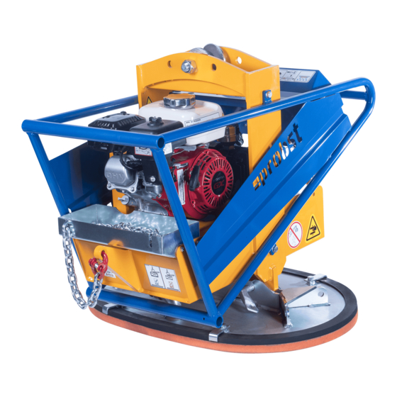
- Page 1 Betriebsanleitung Operating Instructions Instructions d'emploi SH-2500-UNI-B 52400043 DE/GB/FR...
- Page 2 Bitte beachten Sie, dass das Produkt ohne vorliegende Betriebsanleitung in Landessprache nicht eingesetzt / in Betrieb gesetzt werden darf. Sollten Sie mit der Lieferung des Produkts keine Betriebsanleitung in Ihrer Landessprache erhalten haben, kontaktieren Sie uns bitte. In Länder der EU / EFTA senden wir Ihnen diese kostenlos nach.
- Page 3 52400011 SH-2500-UNI-B (neue Warneinrichtung) SH-2500-UNI-B 5240.0011 Vakuum-Anbaugerät SH-2500 Betriebsanleitung Original Betriebsanleitung Vakuum-Anbaugerät SH-2500 SH-2500-UNI-B 5240.0043...
-
Page 4: Table Des Matières
3.13 Sicherheitseinrichtungen prüfen ....................12 3.14 Allgemeines ........................... 13 Bestimmungsgemäßer Einsatz ....................13 Beschreibung ......................... 15 Bestandteile des Hebegerätes SH-2500-UNI-B ................15 Technische Daten ........................16 Bedienelemente ........................16 Akustische Warneinrichtung ....................16 Vakuumpumpe ........................16 Saugplatten ........................... 16 Installation ..........................17 •... -
Page 5: Inhalt
Vakuumpumpe (TFK 12) ......................28 Keilriemen ..........................28 Saugplatten / Dichtlippen ......................28 Filter ............................ 29 Akustische Warneinrichtung ....................29 Dichtheitsprüfung ........................29 • Prüfungspflicht ..........................30 • Hinweis zum Typenschild ....................... 31 • Hinweis zur Vermietung/Verleihung von PROBST-Geräten ..............31 3 / 31... -
Page 6: Eg-Konformitätserklärung
Pos: Pos: 1.3 /02 K onf ormitätserklärung/MRL_ 98/37/EG (gültig bis 29.12. 09) @ 0\mod3 9_1.doc @ 51 86 @ Dokumentationsbevollmächtigter: Name: J. Holderied Anschrift: Probst GmbH; Gottlieb-Daimler-Str. 6; 71729 Erdmannhausen, Germany Unterschrift, Angaben zum Unterzeichner: Erdmannhausen, 18.01.2019................(M. Probst, Geschäftsführer) Pos: 2 /==== ===== ===== ===== ===== ===== == @ 0 \mod8_1. -
Page 7: Sicherheit
Betriebsanleitung Sicherheit SH-2500-UNI-B Pos: 11 /99 gerät espez. Modul e/PG2 Vak uum - Verlegesy steme/ gemeinsame M odule/ gemeinsame M odule Vak uum geräte/Ka p. Sicherheit ( Vorla ge) @ 0\mod472_1. doc @ 1 0888 @ 12223222322 Sicherheit Sicherheitshinweise Lebensgefahr! Bezeichnet eine Gefahr. - Page 8 Betriebsanleitung Sicherheit SH-2500-UNI-B Verbot: außermittiges Positionieren der Saugplatten bei 2904.0337 200x65 mm Verwendung einer Traverse am Vakuum-Anbaugerät. (optional) Lastsicherung bei Verwendung einer Traverse am 29040688 146x85 mm Vakuum-Anbaugerät: (optional) Lastsicherungsketten müssen straff an der Last anliegen. Lastsicherungsketten dürfen niemals locker unter der Last hängen!
- Page 9 Betriebsanleitung Sicherheit SH-2500-UNI-B Täglich Batterietest an Warneinrichtung durchführen 29040444 30x60 mm Bei Nichtgebrauch Benzinhahn schließen, da sonst durch Erschütterung beim Transport, Benzin herausschwappen 29040624 58x50 mm könnte. HINWEISZEICHEN Zuerst Schlauchkupplung festziehen, bevor Schiebeventil 29040392 70x65 mm (Vakuum on-off) betätigt wird.
-
Page 10: Funktions- Und Sichtprüfung
Betriebsanleitung Sicherheit SH-2500-UNI-B Funktions- und Sichtprüfung • Das Gerät muss vor jedem Einsatz auf Funktion und Zustand geprüft werden. • Wartung, Schmierung und Störungsbeseitigung dürfen nur bei stillgelegtem Gerät erfolgen! • Bei Mängeln, die die Sicherheit betreffen, darf das Gerät erst nach einer kompletten Mängelbeseitigung wieder eingesetzt werden. -
Page 11: Hinweise Für Das Betreiberunternehmen
Betriebsanleitung Sicherheit SH-2500-UNI-B Hinweise für das Betreiberunternehmen Das Gerät ist nach dem Stand der Technik gebaut und betriebssicher. Dennoch gehen davon Gefahren aus, • wenn es nicht von geschultem oder zumindest unterwiesenem Personal benutzt wird, • wenn es nicht seiner Bestimmung gemäß eingesetzt wird. -
Page 12: Besondere Gefahren
Betriebsanleitung Sicherheit SH-2500-UNI-B Besondere Gefahren • Arbeitsbereich für unbefugte Personen, insbesondere Kinder, weiträumig absichern. • Arbeitsbereich ausreichend beleuchten. • Vorsicht bei nassen, angefrorenen oder verschmutzten Baustoffen. • Vorsicht bei Gewitter! • Das Arbeiten mit dem Gerät bei Witterungsverhältnissen unter 3 ° C (37,5° F) ist verboten! Es besteht die Gefahr des Herabfallens der Last bedingt durch Nässe oder Vereisung. -
Page 13: Saugplatten
Betriebsanleitung Sicherheit SH-2500-UNI-B 3.11 Saugplatten 3.11.1 Vermeidung von Beschädigungen: • Zur Vermeidung von Beschädigungen (Risse, Materialabrieb) der Gummidichtung an der Saugplatte ist folgendes zu beachten: • Während dem Arbeitseinsatz mit dem Gerät muss generell darauf geachtet werden, dass die Saugplatte weder beim Anheben, Absetzen bzw. -
Page 14: Sicherheitseinrichtungen Prüfen
Betriebsanleitung Sicherheit SH-2500-UNI-B 3.14 Sicherheitseinrichtungen prüfen • Das Gerät verfügt über folgende Manometer mit roter Gefahrenbereichsanzeige Sicherheitseinrichtungen: • Warneinrichtung - akustisch bzw. elektronisch (optional) • Sicherheitseinrichtungen prüfen: bei unterbrochenem Betrieb zu Beginn jeder Arbeitsschicht oder • bei durchgehendem Betrieb einmal wöchentlich Warneinrichtung prüfen:... -
Page 15: Allgemeines
Für die unterschiedlichen Einsatzwecke und Lasten gibt es diverse Saugplatten, die durch einen Schnellwechselverschluss an das Gerät (SH-2500-UNI-B) angebaut werden. • Die zulässige Tragfähigkeit (WLL) des Gerätes (SH-2500-UNI-B) von 2.500 kg darf nicht überschritten werden. • Dieses Gerät ist mit folgender Sicherheitseinrichtung Sicherheitsspeicher (Vakuumtankvolumen 12,5 l). - Page 16 Betriebsanleitung Allgemeines SH-2500-UNI-B • Einige der Saugplatten, die an das Gerät angebaut werden können, reduzieren seine Tragfähigkeit. Auf jeder Saugplatte ist die zulässige Traglast angegeben. • Es dürfen nur für das Gerät zugelassene Saugplatten verwendet werden! • Das Überschreiten der zulässigen und der angegeben Traglast der Saugplatten ist strengstens untersagt!!! Gefahr: Herunterfallen der Last (Steinplatte)! Pos: 8 / 03 Allgem eine s/01 Be stimmungsgemäßer Einsatz/01 Be stimmungsgemäßer Einsatz (Pflicht-Modul e) / ne u_Verbot_ NICHT ERLAUB TE TÄT IGKEITE N (für NICHT Greifgeräte) @ 3\mod_1250497 85 0608_1.doc @ 29051 @...
-
Page 17: Beschreibung
Pos: 15 /99 gerät espez. M odule/ PG2 Vak uum - Verle gesy steme/ SH-25 00- UNI-B/Be schrei bung S H-2500- UNI-B @ 0\m od173_1.doc @ 8172 @ 122222 Beschreibung Bestandteile des Hebegerätes SH-2500-UNI-B Die fettgedruckten Positionen haben Sicherheitsfunktion. Pos. -
Page 18: Technische Daten
Betriebsanleitung Beschreibung SH-2500-UNI-B Technische Daten SH-2500-UNI-B Max. Traglast [WLL] bei -0,6 bar Unterdruck 2.500 kg Gewicht [ kg ] Volumen des Sicherheitsspeicher [ l ] Saugleistung der Vakuumpumpe [ m³/h ] Geräuschpegel [ dB(A) ] ca. 70 Höchstleistung des Motors (bei 3600 1/min) [ kW ] ca. -
Page 19: Installation
Betriebsanleitung Installation SH-2500-UNI-B Pos: 16 /= ===== ===== ===== ===== ===== ===== @ 0\m od8_1. doc @ 515 8 @ Pos: 17 /05 Installati on/KÜ_ Installation @ 0\m od15 _1.doc @ 5466 @ 1 Installation Pos: 18 / 05 Installation/ 01 Mecha nischer Anbau/ Ü_M echa nischer A nbau @ 0\mod105_1.doc @ 7346 @ •... -
Page 20: Optionales Zubehör (Sh-2500-Rs Und Sh-2500-Hgv)
Betriebsanleitung Installation SH-2500-UNI-B Optionales Zubehör (SH-2500-RS und SH-2500-HGV) SH-2500-RS • Um den Arbeitsradius zu erweitern, wird die Nachrüstung des Radsatzes SH-2500-RS empfohlen. • Der Radsatz besteht aus zwei aufsteckbaren Haupträdern (Ø 300 mm) und einer abklappbaren Stütze mit Lenkrolle. Der nachträgliche Anbau an das Basisgerät SH ist problemlos möglich. -
Page 21: Verwendung Der Optionalen Traverse Mit 2 (3) Saugplatten
Betriebsanleitung Installation SH-2500-UNI-B Pos: 20 / 99 geräte spez. Module/ PG2 Vakuum-Verl ege system e/SH -2500-UNI-B /Install.-Trav erse (525 001 66) mit 2 SPS. _SH.. .VPM @ 2\mod1 024_1. doc @ 8102 @ 2 Verwendung der optionalen Traverse mit 2 (3) Saugplatten Bei der Verwendung der Traverse mit 2 Saugplatten dürfen nur Saugplatten der gleichen Bauart... -
Page 22: Befestigen Der Lastsicherungsketten (Der Optionalen Traverse)
Betriebsanleitung Installation SH-2500-UNI-B Befestigen der Lastsicherungsketten (der optionalen Traverse) • Das Gerät mit der angesaugten Last etwas anheben (ca. 20-30 cm). • Beide Lastsicherungsketten aus den Kettenkästen der Traverse (TRA) entnehmen. • Lastsicherungsketten unter der angehobenen Last durchwerfen (durchführen). Niemals dabei unter die Last (Steinplatte) mit den Händen fassen! Quetschgefahr!!! •... -
Page 23: Bedienung
Betriebsanleitung Bedienung SH-2500-UNI-B Pos: 22 /99 geräte spez. Modul e/PG2 Vakuum-Verlegesyst eme/S H-2500- UNI-B/Be dienung SH uni2500 b/SH.. . @ 0\m od175 _1.doc @ 82 00 @ 1223333 Bedienung Arbeitssicherheitshinweise • Sicherheitsschuhe und Arbeitshandschuhe tragen. • Maximale Tragkraft des Gerätes nie überschreiten. Maximale Tragkraft des verwendeten Hebezeuges nie überschreiten. -
Page 24: Last Anheben
Betriebsanleitung Bedienung SH-2500-UNI-B 7.2.1 Last anheben: • Benzinmotor (weitere Details - siehe Bedienungsanleitung HONDA) starten und Warneinrichtung einschalten. • Gerät direkt über der Last positionieren. Schrägziehen vermeiden. Auf gleichmäßige Lastverteilung achten. • Gerät auf die Last aufsetzen. • Hülse am Schiebeventil (6) verschieben. Die Last wird angesaugt. -
Page 25: Last Ablegen
Betriebsanleitung Bedienung SH-2500-UNI-B 7.2.2 Last ablegen • Gerät mit angesaugter Last komplett auf dem Boden absetzen. • Hülse am Schiebeventil (6) zurückschieben. Die Last löst sich. 7.2.3 Feuchte Lasten heben • Das Gerät ist bestimmungsgemäß nicht für das Ansaugen von nassen Werkstücken geeignet, deshalb bei nassen Werkstücken:... -
Page 26: 7.2.4 Stillstandszeiten
Betriebsanleitung Bedienung SH-2500-UNI-B • Kondensat-Ablassschraube des Speicherbehälters an der Geräteunterseite öffnen. Wasser vollständig ablaufen lassen. • Anschließend Ablassschraube wieder dicht verschrauben. Ablassschraube 7.2.4 Stillstandszeiten Die Geräteaufbewahrung muss in einem geschlossenen und frostfreien Raum erfolgen (nicht ungeschützt im freien Gelände) Pos: 23 /==== ===== ===== ===== ===== ===== == @ 0\mod8_1. doc @ 5158 @... -
Page 27: Fehlersuche, Abhilfe
Betriebsanleitung Fehlersuche, Abhilfe SH-2500-UNI-B Pos: 24 / 99 geräte spez. M odule/ PG2 Va kuum - Verle ge systeme /SH-25 00-UNI-B/ Fehl ersuc he SH -2500-UNI-B /SH.. . @ 0\m od17 6_1. doc @ 8214 @ 1 Fehlersuche, Abhilfe Das Gerät darf nur von qualifiziertem Fachpersonal, Mechaniker und Elektriker installiert und gewartet werden. -
Page 28: Wartung Und Pflege
Betriebsanleitung Wartung und Pflege SH-2500-UNI-B Pos: 26 / 99 geräte spez. Module /PG2 Vakuum-Verl ege system e/S H-2500-UNI -B/Wart ung SH-25 00- UNI-B/S H... @ 0\mod177_1. doc @ 8228 @ 1222222 Wartung und Pflege Pos: 31.2 /07 Wart ung und Pflege /01 Wart ung/ Ü_Wart ung+T ext allg. (nur mecha n. Geräte) @ 0\mod27_1. doc @ 7122 @ Wartung Um eine einwandfreie Funktion, Betriebssicherheit und Lebensdauer des Gerätes zu gewährleisten, sind die in... -
Page 29: Wartungsintervalle
Betriebsanleitung Wartung und Pflege SH-2500-UNI-B Wartungsintervalle Die jährliche Prüfung ist durch einen Sachkundigen durchzuführen. Intervall Täglich Wöchent- Monat- 1/2- Jährlich lich lich jährlich Sicherheitseinrichtungen prüfen : Vakuum-Manometer Warneinrichtung (Batterietest) schaltet bei korrektem Unter-/Überdruck Lastsicherungskette Sichtprüfung 1) Vakuum-Filter überprüfen, ggf. austauschen Benzinmotor (siehe auch separate Betriebsanleitung) Keilriemenspannung prüfen, ggf. -
Page 30: Vakuumpumpe (Tfk 12)
Betriebsanleitung Wartung und Pflege SH-2500-UNI-B Vakuumpumpe (TFK 12) Siehe beiliegende Bedienungsanleitung der Vakuumpumpe (im Anhang). Keilriemen • Die Keilriemenspannung ist monatlich zu überprüfen. • Keilriemen darf sich maximal 1 cm durchdrücken lassen, ansonsten muss er nachgespannt werden. • Vorgehensweise: •... -
Page 31: Filter
Betriebsanleitung Wartung und Pflege SH-2500-UNI-B Filter • Filter mindestens einmal wöchentlich kontrollieren und Filterpatrone ausblasen (von innen nach außen). Filter nicht ausklopfen. • Bei starker Verschmutzung die Filterpatrone wechseln. • Beim Herausnehmen der Filterpatrone keinen Staub in die Saugleitung gelangen lassen. -
Page 32: Prüfungspflicht
100-500). • Die dementsprechenden gesetzlichen Bestimmungen u. die der Konformitätserklärung sind zu beachten! • Die Durchführung der Sachkundigenprüfung kann auch durch den Hersteller Probst GmbH erfolgen. Kontaktieren Sie uns unter: service@probst-handling.com • Wir empfehlen, nach durchgeführter Prüfung und Mängelbeseitigung des Gerätes die Prüfplakette „Sachkundigenprüfung / Expert inspection“... -
Page 33: Hinweis Zum Typenschild
Beispiel: • Hinweis zur Vermietung/Verleihung von PROBST-Geräten Bei jeder Verleihung/Vermietung von PROBST-Geräten muss unbedingt die dazu gehörige Original Betriebsanleitung mitgeliefert werden (bei Abweichung der Sprache des jeweiligen Benutzerlandes, ist zusätzlich die jeweilige Übersetzung der Original Betriebsanleitung mit zuliefern)! Pos: 31 /==== ===== ===== ===== ===== ===== == @ 0 \mod8_1.doc @ 5158 @... -
Page 35: Beschreibung
Bedienungsanleitung Warneinrichtung SH 2500 uni-b, (akustisch, batteriebetrieben) BA 30.12.01.00075 Status 03.2010 / Index 00 Seite / Page 1/3 (42500190) 1. Sicherheit Hinweise für das Installations-, Wartungs- und Bedienpersonal Das Gerät darf nur von qualifiziertem Fachpersonal installiert und gewartet werden. Jede Person, die im Betrieb des Anwenders mit der Aufstellung, Inbetriebnahme, Bedienung, Wartung und Reparatur des Gerätes beauftragt ist, muss die Betriebsanleitung und besonders das Kapitel "Sicherheit"... - Page 36 Bedienungsanleitung Warneinrichtung SH 2500 uni-b, (akustisch, batteriebetrieben) BA 30.12.01.00075 Status 03.2010 / Index 00 Seite / Page 2/3 (42500190) Um ein sicheres Arbeiten der Warneinrichtung zu gewährleisten, ist vor jedem Geräteeinsatz immer ein Funktionstest durchzuführen! Vorsicht Während der Arbeit sollte das am Hebegerät angebrachte Manometer immer im Auge behalten werden um Vakuumabfall parallel zur Warneinrichtung erkennen zu können! Vorsicht Nr.
- Page 37 Bedienungsanleitung Warneinrichtung SH 2500 uni-b, (akustisch, batteriebetrieben) BA 30.12.01.00075 Status 03.2010 / Index 00 Seite / Page 3/3 (42500190) 5. Wartung Zur Wartung des Gerätes genügt es, den vorgeschriebenen Funktionstest täglich oder vor Arbeitsbeginn durchzuführen. Bei längerem Stillstand des Gerätes Batterien aus dem Gerät entfernen. Vakuumschläuche sind monatlich auf Dichtheit und Beschädigungen zu überprüfen.
- Page 39 Betriebsanleitung Vakuumpumpe TFK 12 Vakuumpumpe TFK 12...
- Page 40 Betriebsanleitung Vakuumpumpe TFK 12 Inhalt Technische Daten ........................3 Kennlinie (bei 1400 1/min)......................3 Bestimmungsgemäßer Gebrauch ....................4 Technische Besonderheiten - Maßblatt..................4 Allgemeine Sicherheitshinweise ....................5 Spezielle Sicherheitshinweise ......................6 Inbetriebnahme ..........................7 Arbeitshinweise ..........................8 Betriebsstörungen ........................8 Wartung und Reinigung........................9 Schieberwechsel ........................10 Gewährleistung ..........................10...
-
Page 41: Technische Daten
Betriebsanleitung Vakuumpumpe TFK 12 Technische Daten Pumpendaten: Alle Daten beziehen sich auf eine Wellendrehzahl von 1400 1/min max. Volumenstrom 12 m³/h max. abs. Vakuum 200 mbar max. Überdruck 1 bar (S3 10%) Anschlussgewinde 1 x G ¾ saugseitig Anschlussgewinde 1 x G ¾ druckseitig LängexBreitexHöhe ca. -
Page 42: Bestimmungsgemäßer Gebrauch
Betriebsanleitung Vakuumpumpe TFK 12 Bestimmungsgemäßer Gebrauch Die Pumpen sind nur zum Ansaugen von Luft ausgelegt; das Ansaugen anderer Gase oder gar Flüssigkeiten ist unzulässig! Der Betrieb in explosionsgefährdeten Bereichen (z.B. in unmittelbarer Nähe von Gastanks) ist verboten. Das Fördern brennbarer oder explosiver Gase ist unzulässig. Betreiben Sie die Pumpe nur innerhalb den angegebenen Druckgrenzen. -
Page 43: Allgemeine Sicherheitshinweise
Betriebsanleitung Vakuumpumpe TFK 12 Allgemeine Sicherheitshinweise Bedienungsanleitung Augenschutz tragen Schutzhandschuhe Gehörschutz tragen lesen tragen Halten Sie Ihren Arbeitsbereich in Ordnung! Unordnung am Arbeitsplatz ergibt Unfallgefahr. Berücksichtigen Sie Umgebungseinflüsse! Setzen Sie Elektrogeräte nicht dem Regen aus. Benützen Sie Elektrogeräte nicht in feuchter Umgebung. Sorgen Sie für gute Beleuchtung. -
Page 44: Spezielle Sicherheitshinweise
Betriebsanleitung Vakuumpumpe TFK 12 Spezielle Sicherheitshinweise Gefahrloses Arbeiten mit der Pumpe ist nur möglich, wenn Sie die Bedienungsanleitung vollständig und aufmerksam lesen und die darin enthaltenen Anweisungen strikt befolgen. Prüfen Sie vor jedem Gebrauch Gerät, Kabel, Stecker, Schlauch und Anschlüsse auf Beschädigungen. -
Page 45: Inbetriebnahme
Betriebsanleitung Vakuumpumpe TFK 12 Inbetriebnahme Achtung! Die Pumpe wird im Betrieb sehr heiß! Verbrennungsgefahr! Montieren Sie die Pumpe auf eine feste, waagerechte Unterlage. Kuppeln Sie Ihren Antrieb an das freie Wellenende der Pumpe an; vermeiden Sie hierbei Fluchtungsfehler. Bei Verwendung eines Riementriebes beträgt die maximale Riemenvorspannung 110 N. Prüfen Sie die Drehrichtung. -
Page 46: Arbeitshinweise
Betriebsanleitung Vakuumpumpe TFK 12 Arbeitshinweise Tragen Sie Schutzausrüstung bei der Arbeit! Sollte die Pumpenleistung unzureichend sein, unterbrechen Sie Ihre Arbeit und überprüfen Sie das System auf Undichtigkeiten, geknickte Schläuche etc. Lassen Sie aufgetretene Schäden vom Fachmann reparieren. Betriebsstörungen Die folgende Tabelle gibt einen Auszug möglicher Störungen und deren Ursachen wieder. Sollten Sie den Fehler nicht beheben können, so schicken Sie die Pumpe bitte an den Hersteller zur Reparatur. -
Page 47: Wartung Und Reinigung
Betriebsanleitung Vakuumpumpe TFK 12 Wartung und Reinigung Achtung! Die Pumpe wird im Betrieb sehr heiß! Verbrennungsgefahr! Ölen Sie niemals Teile der Pumpe. Alle beweglichen Pumpenteile sind wartungsfrei und bedürfen keiner Schmierung. Schmierstoffe in der Pumpe können zum Ausfall führen. Trennen Sie vor allen Wartungsarbeiten die Pumpe von der Stromzufuhr. In der Pumpe befinden sich Kohleschieber, die im Laufe der Zeit verschleißen. -
Page 48: Schieberwechsel
Betriebsanleitung Vakuumpumpe TFK 12 Schieberwechsel Trennen Sie die Pumpe von der Stromzufuhr. Markieren Sie die Lage des Deckels zum Gehäuse und lösen Sie die 4 Hutmuttern M8 am Pumpenkopf. Heben Sie den Pumpendeckel ab. Entnehmen Sie die Schieber und prüfen Sie deren Verschleißlänge. Sollte diese weniger als 18 mm betragen, so tauschen Sie die Schieber gegen neue. - Page 49 GX120 GX160 GX200 Seriennumber und motortyp BEDIENUNGSANLEITUNG 34ZH7620 00X34-ZH7-6201 HONDA EUROPE N.V.(EEC) www.honda-engines-eu.com...
- Page 50 Wir danken Ihnen für den Kauf eines Honda-Motors. Dieses Handbuch behandelt die Bedienung und Wartung der Motoren GX120 GX160 GX200 Alle in dieser Veröffentlichung enthaltenen Informationen beruhen auf der neuesten Produktinformation, die zum Zeitpunkt der Druckgenehmigung erhältlich war. Honda Motor Co., Ltd. behält sich das Recht vor, Änderungen jederzeit und ohne Vorankündigung vorzunehmen, ohne irgendwelche Verpflichtungen einzugehen.
- Page 51 SICHERHEITSANWEISUNGEN Sicherer Betrieb − Honda-Motoren sind für einen sicheren und zuver- l ä s s i g e n B e t r i e b a u s g e l e g t , s o f e r n s i e entsprechend den Anweisungen betrieben w e r d e n .
-
Page 52: Lage Der Sicherheitsaufkleber
SICHERHEITSANWEISUNGEN Sicherer Betrieb − Keine Gegenstände auf den Motor legen, um die Gefahr eines Feuers zu vermeiden. Für diesen Motor ist ein Funkenfänger als Zusatzeinrichtung erhältlich. In manchen Gebieten ist der Betrieb mit einem Funkenfänger gesetzlich vorgeschrieben, daher vor der Inbetriebnahme die örtlichen Vorschriften und Verordnungen überprüfen. - Page 53 BATTERIEANSCHLÜSSE (für elektrischen Anlasser) Eine 12-Volt-Batterie mit einer Kapazität von mindestens 18 Ah verwenden. Das Batterie-Pluskabel ( ) wie gezeigt am Anlasser-Magnetschalter + befestigen. Das negative ( ) Batteriekabel an eine Motorbefestigungsschraube, − Rahmenschraube oder eine andere geeignete Stelle der Motormasse anschließen.
- Page 54 ÜBERPRÜFUNGEN VOR DER INBETRIEBNAHME Motorölstand Wenn der Motor mit einer ungenügenden Ölmenge betrieben wird, kann dies einen schweren Motorschaden zur Folge haben. Die Überprüfung des Generators auf ebenem Untergrund mit gestopptem Motor durchführen. Den Öleinfüllverschluß entfernen, und den Ölmeßstab sauberwischen. Den Meßstab in den Öleinfüllstutzen einsetzen, jedoch nicht hineinschrauben.
- Page 55 Untersetzungsgetriebeöl Den Untersetzungsgetriebeölstand kontrollieren. Gegebenenfalls Motoröl der Klasse SG, SF nachfüllen. 〈 1/2 Untersetzung mit automatischer Fliehkraftkupplung 〉 Den Öleinfüllverschluß entfernen, und den Ölmeßstab sauberwischen. Den Meßstab in den Einfüllstutzen einsetzen, jedoch nicht hineinschrauben. Den Ölstand am Meßstab kontrollieren. Wenn der Motorölstand zu niedrig ist, mit dem empfohlenen Motoröl bis zur oberen Markierung affüllen (siehe Motoröl-Hinweise auf Seite Ölfassungsvermögen: 0,50...
- Page 56 Luftfilter Den Motor niemals ohne Luftfilter laufen lassen, da dies zu beschleunigtem Ver- schleiß des Motors führt. FILTEREINSATZE 〈 Zwei-Element-Ausführung 〉 Die Luftfiltereinsätze überprüfen, um sicherzustellen, daß diese sauber und in gutem Zustand sind. Die Einsätze erforderlichenfalls reinigen oder auswechseln (Seite (GX120/160) (GX120/160/200) 〈...
- Page 57 〈 Halbtrockentyp 〉 Den Luftfilter auf Schmutz oder Verstopfung des Einsätz überprüfen (Seite FILTEREINSATZ 〈 Ölbad-Ausführung 〉 Den Luftfiltereinsatz überprüfen und sich vergewissern, daß er nicht verschmutzt ist oder Beschädigungen aufweist. Den Einsatz-wenn erforderlich-reinigen oder ersetzen (Seite Den Ölzustand und -pegel überprüfen. Den Motor niemals ohne Luftfilter laufen lassen, da dies zu beschleunigtem Verschleiß...
- Page 58 Kraftstoff Kraftfahrzeugbenzin verwenden (vorzugsweise unverbleiten oder Kraftstoff mit niedrigem Bleigehalt verwenden, um die Verbren- nungsrückstände auf ein Minimum zu beschränken). Niemals ein Öl-Benzin-Geisch oder schmutziges Benzin verwenden. Eindringen von Schmutz, Staub oder Wasser in den Kraftstofftank vermeiden. Benzin ist sehr leicht entflammbar und unter bestimmten Bedingungen explosiv.
- Page 59 ALKOHOLHALTIGES BENZIN Falls Sie sich für die Verwendung von alkoholhaltigem Benzin (Gasohol) entscheiden, vergewissern Sie sich, daß seine Oktanzahl mindestens so hoch ist wie die für bleifreies Benzin empfohlene. Es gibt zwei Arten von ‘‘Gasohol’’: die eine enthält Äthanol, und die andere Methanol. Verwenden Sie kein Gasohol, das mehr als 10% Äthanol enthält.
-
Page 60: Anlassen Des Motors
ANLASSEN DES MOTORS Den Kraftstoffhahn auf ON aufdrehen. KRAFTSTOFFHAHN ……ON Den Chokehebel auf die CLOSE-Stellung schieben. Den Choke nicht benutzen, wenn der Motor warm oder die Lufttemperatur hoch ist. CHOKEHEBEL GESCHLOSSEN……... - Page 61 Den Gashebel etwas nach links schieben. SCHNELL LANGSAM DROSSELKLAPPENHEBEL Den Motor anlassen. Mit Rücklaufstarter: Den Motorschalter auf ON stellen. ZÜNDSCHALTER AUF (ON)
- Page 62 Den Anlassergriff leicht ziehen, bis Widerstand zu spüren ist, dann den Griff kräftig durchziehen. Den Anlassergriff nicht gegen den Motor zurückschnellen lassen. Den Griff vorsichtig zurückbewegen, um eine Beschädigung des Anlassers zu verhindern. Mit elektrischem Starter (bei ent- sprechender Ausstattung): START Den Motorschalter zur Stellung START drehen und diesen dort...
-
Page 63: Bedienung
BEDIENUNG Wührend der Warmlaufzeit des Motors den Chokehebel nach und nach zur OPEN-Stellung (OFFEN) schieben. CHOKEHEBEL ……OPEN Ö Ö Mit dem Gashebel die gewünschte Motordrehzahl einstellen. GASHEBEL SCHNELL LANGSAM... - Page 64 Ölwarnsystem (bei entsprechender Ausstattung) Das Ölwarnsystem dient zur Vermeidung von Motorschäden, sollte im Kur- belgehäuse eine ungenügende Motorölmenge vorhanden sein. Vor dem Absinken des Motorölstandes unter die Sicherheitsgrenze schaltet das Öl- warnsystem automatisch den Motor ab (der Motorschalter bleibt dabei in der ON-Stellung).
-
Page 65: Abstellen Des Motors
ABSTELLEN DES MOTORS Um den Motor in einer Notsituation abzustellen, den Motorschalter auf OFF stellen. Normalerweise den Motor folgendermaßen abstellen: Den Geshebel ganz nach rechts schieben. DROSSELKLAPPENHEBEL LANGSAM Den Motorschalter auf OFF drehen. ZÜNDSCHALTER Den Kraftstoffhahn auf OFF drehen. KRAFTSTOFFHAHN OFF……... - Page 66 WARTUNG Vor dem Beginn der Wartungsarbeiten den Motor abstellen. Um ein unbeabsichtigtes Anlassen zu vermeiden, den Motorschalter ausschalten und den Zündkerzenstecker abziehen. Der Motor sollte von einem autorisierten Honda-Händler gewartet werden, es sei denn, der Eigentümer besitzt die erforderlichen Werkzeuge und Wartungsdaten, und verfügt über die nötigen handwerklichen Fähigkeiten.
- Page 67 Wartungsplan NORMALE WARTUNGSINTERVALLE Erste Nach dem Alle 3 Alle 6 Alle Nach jedem angezeigten monatlichen oder Betriebs- inspektion ersten Monate Monate Jahre stunden-intervall durchzuführen, jenachdem wes Monat oder oder oder oder zueret eintritt. 20 Std. 50 Std. 100 Std. 300 Std. GEGENSTAND Motoröl Füllstand kontrollieren...
- Page 68 Ölwechsel Das Öl bei noch warmem Motor ablassen, um ein rasches und vollständiges Ablassen zu gewährleisten. Öleinfüllverschluß und Ablaßschraube zum Ablassen des Öls entfernen. Die Ablaßschraube wieder hineinschrauben und fest anziehen. Das empfohlene Öl einfüllen (siehe Seite ) und den Ölstand überprüfen.
- Page 69 Reinigen des Luftfilters Ein schmutziger Luftfilter behindert den Luftstrom zum Vergaser. Um Vergaserstörungen zu vermeiden, den Luftfilter regelmäßig reinigen. Den Filter häufiger reinigen, wenn der Motor in äußerst staubiger Umgebung betrieben wird. Niemals Benzin oder Reinigungslösungen mit niedrigem Flammpunkt zum Reinigen des Luftfiltereinsatzes verwenden.
- Page 70 〈 Zyklon-Typ 〉 Die Flügelmuttern und den Luftfilterdec- FLÜGELMUTTER kel entfernen. Die Einsätze herausneh- PAPIEREINSATZ men und trennen. Beide Einsätze sorgfältig auf Löcher oder Risse überprü- fen und diese bei Beschädigung auswechseln. Schaumeinsatz: Den Einsatz in warmem Seifenwasser auswaschen, abspülen u n d g r ü...
- Page 71 〈 Halbtrockentyp 〉 Die Flügelmutter abschrauben, den FLÜGELMUTTER Luftfilterdeckel entfernen und den Einsatz herausnehmen. LUFTFILTERDECKEL Den Einsatz in nichtbrennbarer Reini- gungslösung oder in solcher mit hohem Flammpunkt auswaschen und gründlich trocknen lassen. FILTEREINSATZ Den Einsatz mit sauberem Motoröl durch- tränken und überschüssiges Öl ausdrücken. Den Luftfiltereinsatz und Deckel wieder anbringen.
- Page 72 Reinigen des Filterbechers Benzin ist extrem feuergefährlich und unter gewissen Bedingungen explosiv. Im Arbeitsbereich nicht rauchen und offene Flammen und Funken fernhalten. Nach Anbringen des Filterbechers auf Undichtigkeit überprüfen und sicherstellen, daß der Bereich trocken ist, bevor der Motor angelassen wird.
- Page 73 Das Äußere der Zündkerze überprüfen. Die Kerze wegwerfen, wenn sie sichtlich abgenutzt oder der Isolator gerissen bzw. abgesplittert ist. Wenn die Zündkerzen wiederverwendet werden sollen, sie mit einer Drahtbürste reinigen. Den Elektrodenabstand mit einer Fühlerlehre messen. Den Abstand erforderlichenfalls durch entsprechendes Biegen der Masseelektrode berichtigen.
- Page 74 Reinigen des Funkenfängers (Sonderzubehör) Beim Betreiben des Motor wird der Auspuff sehr heiß. Den Auspuff deshalb vor weiteren Arbeiten am Motor abkühlen lassen. Der Funkenfänger muß alle 100 Betriebsstunden gereinigt werden, um seine Leistungsfähigkeit aufrechtzuerhalten. Die beiden 4 mm-Schrauben vom Auspuffablenkblech entfernen und das Ablenkblech abnehmen.
- Page 75 Vergaser-Leerlaufeinstellung Den Motor anlassen und bis zur n o r m a l e n B e t r i e b s t e m p e r a t u r warmlaufen lassen. Bei laufendem Motor die Drosselklap- pen-Anschlagschraube verstellen, um die standard-Leerlaufdrehzahl zu erzie- len.
- Page 76 DROSSELKLAPPEN- UND CHOKEZUG (ZUSATZAUSRÜSTUNG) Die Drosselklappen- und Chokehebel sind mit Bohrungen versehen, die ei- ne Montage der als Zusatzausrüstung erhältlichen Kabelzüge erlauben. Die nachfolgende Abbildung zeigt die Einbaubeispiele für einen Volldraht-Ka- belzug und einen beflochtenen Kabelzug. Wenn ein beflochtener Zug ver- wendet wird, muß...
- Page 77 TRANSPORT/LAGERUNG Beim Transport des Motors das Kraftstoffventil auf OFF stellen und den Motor waagerecht halten, um ein Auslaufen des Kraftstoffs zu vermeiden. Verschütteter Kraftstoff oder Kraftstoffdämpfe können sich entzünden. Vor dem Einlagern des Geräts für längere Zeit: Sich vergewissern, daß der Aufbewahrungsort frei von übermäßiger Feuchtigkeit und Staub ist.
- Page 78 STÖRUNGSBESEITIGUNG Der Motor springt beim Anlassen mit dem Rücklaufstarter nicht an: Ist der Motorschalter auf ON gestellt? Befindet sich ausreichend Öl im Motor? Steht das Kraftstoffventil auf ON? Befindet sich Kraftstoff im Tank? Wird der Vergaser mit Kraftstoff versorqt? Zur Überprüfung die Ablaßschraube bei geöffnetem Kraftstoffventil lösen.
-
Page 79: Technische Daten
TECHNISCHE DATEN * Abmessungen GX 120 GX 160 GX 200 Bezeichungscode für motorgetriebene GC01 GC02 GCAE Produkte Länge 300 mm 305 mm 313 mm Breite 345 mm 365 mm 376 mm Höhe 320 mm 335 mm 335 mm 〈 〉 〈... - Page 80 Mit Zyklon-Luftfilter * Abmessungen GX 120 GX 160 GX 200 Bezeichungscode für motorgetriebene GC01 GC02 GCAE Produkte Länge 310 mm 345 mm 313 mm Breite 410 mm 420 mm 430 mm Höhe 325 mm 335 mm 335 mm Leergewicht 12,0 kg 14,0 kg 16,0 kg Motor...
- Page 81 (durch eine autorisierte Fachwerkstatt)! Nach jeder erfolgten Durchführung eines Wartungsintervalls muss unverzüglich dieser Wartungsnachweis (mit Unterschrift u. Stempel) an uns übermittelt werden 1). 1) per E-Mail an: service@probst-handling.de / per Fax oder Post Betreiber: _ _ _ _ _ _ _ _ _ _ _ _ _ _ _ _ _ Gerätetyp:...
- Page 83 52400011 SH 2500 uni b (neue Warneinrichtung) SH 2500-UNI-B 5240.0011 Vacuum Lifting Device SH-2500 Operating Instructions Translation of original operating instructions Vacuum Lifting Device SH-2500 SH 2500-UNI-B 52400043...
- Page 84 Operating Instructions Contents SH 2500-UNI-B 1 Contents Contents ................................. 2 EC-Declaration of Conformity ..........................4 Safety ..................................5 Safety Symbols ..............................5 Safety Marking ..............................5 3.1.1 Function Control ............................8 Safety at work ..............................8 Instructions for the Company .......................... 9 Instructions for Installation, Maintenance and Operating Personnel ............
- Page 85 Vacuum filter ..............................30 10.7 Warning device (audible) ..........................30 10.8 Leak test ................................. 30 10.9 Safety procedures ............................31 10.10 Hints to the identification plate........................32 10.11 Hints to the renting/leasing of PROBST devices ................... 32 3 / 32...
-
Page 86: Ec-Declaration Of Conformity
Pos: 1.10 / 02 Konformitätserklär ung/5 neu_ Angaben zum Unterzeichner + D ok ubev ollmächtigt er @ 0\mod55_2.doc @ 53 41 @ Authorized person for EC-documentation: Name: J. Holderied Address: Probst GmbH; Gottlieb-Daimler-Str. 6; 71729 Erdmannhausen, Germany Signature, informations to the subscriber: Erdmannhausen, 18.01.2019................ -
Page 87: Safety
Operating Instructions Safety SH 2500-UNI-B Pos: 10 /= ===== ===== ===== ===== ===== ===== @ 0\m od8_2. doc @ 515 9 @ Pos: 11 /99 gerät espez. Modul e/PG2 Vak uum - Verlegesy steme/ gemeinsame M odule/ gemeinsame M odule Vak uum geräte/Ka p. Sicherheit ( Vorla ge) @ 1\m od472_2.doc @ 10889 @ 12223222322 Safety Safety Symbols Danger to life! - Page 88 Operating Instructions Safety SH 2500-UNI-B It is not allowed to position suction plates off-centre. 29040337 (optional) Load securing with the use of a spreader bar (TRA) on 29040688 the vacuum lifting device: (optional) The safety chains must fit tightly to the load Prohibition: safety chains must never hang loose under the load! WARNING SIGN...
- Page 89 Operating Instructions Safety SH 2500-UNI-B 29040444 30x60 mm Close the petrol cock when not in use, as gasoline may 29040624 58x50 mm escape if shaken during transport INFORMATIONS SIGNS First tighten the hose coupling before actuating the slide 29040392 70x65 mm valve (vacuum on-off).
-
Page 90: Function Control
Operating Instructions Safety SH 2500-UNI-B 3.1.1 Function Control ● Before using the device check the functions and the working condition. ● Maintenance and lubrication are only permitted when device is shut down! ● Do not use the device, until all faults which can cause safety hazards are removed. ●... -
Page 91: Instructions For The Company
Operating Instructions Safety SH 2500-UNI-B Instructions for the Company The lifting devices are manufactured according to current technical standards and are safe. However, they will present hazards ● if they are not operated by qualified or, at the least, trained staff, ●... -
Page 92: Special Hazards
Operating Instructions Safety SH 2500-UNI-B Special Hazards ● The operating range has to be covered for unauthorized persons, especially children. ● The workplace has to be sufficiently illuminated. ● Take care when handling wet, dirty and not solidified components. ● The working with the vacuum lifting device in case of atmospheric editions under 3°... -
Page 93: Testing The Safety Devices
Operating Instructions Safety SH 2500-UNI-B Testing the Safety Devices The lifting device is equipped with following safety equipment: ● pressure gauge (with red danger zone display) ● alarm signal (audio) Check this equipment ● at the beginning of each shift (when operating in shifts), ●... -
Page 94: Behaviour In Emergencies
Operating Instructions Safety SH 2500-UNI-B 3.11 Behaviour in Emergencies An emergency situation exists when ● power suddenly fails (device switches off), ● the vacuum pressure drops below -0.6 bar to the red section on the scale of the vacuum gauge. Lower the load immediately if possible. - Page 95 Operating Instructions Safety SH 2500-UNI-B Checking the Vacuum Hoses and Check all vacuum hoses and clamps for proper mounting and tighten the clamps if Hose Clamps: necessary. Checking the Vacuum Reservoir See “Testing for Leaks"“ in chapter “Maintenance“ Correct any faults before using the device. If faults occur during operation, switch the device off and correct the faults before continuing work with the device.
-
Page 96: General
Various suction plates can be fitted to the device (SH 2500 UNI B) via a quick release locating pin, enabling it to be used for many different purposes and with many different loads. ● The carrying capacity/working load limit (WLL) of the device (SH-2500-UNI-B) of 2.500kg must not be exceeded! ● This device is equipped with the following safety Safety vacuum storage tank (12,5 l). - Page 97 Operating Instructions General SH 2500-UNI-B • Some suction plates which can be mounted to the device will reduce its carrying capacity. The maximum load is indicated on each suction plate. • Use only suction plates which are approved for this device! •...
-
Page 98: Description
Operating Instructions Description SH 2500-UNI-B Pos: 15 /99 gerät espez. M odule/ PG2 Vak uum - Verle gesy steme/ SH UNI 25 00 b/Be schrei bung S H uni 25 00 b @ 0\m od173 _2.doc @ 8173 @ 122222 Description Components of the lifting device SH 2500 uni b Parts that have a safety function appear in bold type. -
Page 99: Technical Data
Operating Instructions Technical Data SH 2500-UNI-B Pos: 13 /99 gerät espez. M odule/ PG2 Vak uum- Verle gesy steme/ SH UNI 25 00 b/T echni sche Dat en S H uni 2500 b @ 0\m od172_2.doc @ 815 9 @ 1 Technical Data SH 2500 uni b Max. -
Page 100: Installation
Operating Instructions Installation SH 2500-UNI-B Pos: 17 /05 Installati on/KÜ_ Installation @ 0\m od15 _2.doc @ 5467 @ 1 Installation Pos: 18 / 05 Installation/ 01 Mecha nischer Anbau/ Ü_M echa nischer A nbau @ 0\mod105_2.doc @ 7347 @ Mechanical connection Pos: 19 / 99 geräte spez. -
Page 101: Optional Accessoires (Sh-2500-Rs And Sh-2500-Hgv)
Operating Instructions Installation SH 2500-UNI-B Optional Accessoires (SH-2500-RS and SH-2500-HGV) SH-2500-RS • To extend the working radius of Micro Jumbo MJ at any time, we recommend the solid set of wheels for later equipment. • The wheelset consists of two attachable main wheels (diameter Ø 300 mm), one foldable support-wheel and one swivelling wheel. -
Page 102: Use Of The Spreader Bar With 2 (3) Suction Plates
Operating Instructions Installation SH 2500-UNI-B Use of the spreader bar with 2 (3) suction plates When using the crossbar with 2 suction plates only suction plates of the same design (carrying capacity, dimensions and form) may be used! The suction plates must always have the same distance (A) to the vertical centre axis of the crossbar (see figure 1). Unequal positioning of the suction plates is not permitted (see figure 2)! Take care that the load (stone slab) hangs always horizontal. -
Page 103: Attaching The Safety Chain (Of The Optional Spreader Bar)
Operating Instructions Installation SH 2500-UNI-B 7.6.1 Attaching the safety chain (of the optional spreader bar) ● Lift the device with the sucked load just a little (approx.. 20-30 cm) ● Then remove both safety chains from the chain cases of the spreader bar (TRA). ●... -
Page 104: Operating
Operating Instructions Operating SH 2500-UNI-B Pos: 22 /99 geräte spez. Modul e/PG2 Vakuum-Verlegesyst eme/S H UNI 2500 b/Bedi enung SH uni2500 b/ SH... @ 0\m od175_2. doc @ 8201 @ 1223333 Operating Safety Instructions ● Wear safety shoes and gloves. ●... -
Page 105: Lifting And Landing Loads
Operating Instructions Operating SH 2500-UNI-B Lifting and Landing Loads The following operating steps must be checked by a qualified mechanic before the operating staff can use the device. Correct faults before start-up. In order to ensure safe operation of the device, a battery test of the warning device must be carried out before each use of the device. -
Page 106: 8.2.2 Lowering Loads
Operating Instructions Operating SH 2500-UNI-B Fig. A 8.2.2 Lowering Loads: ● Lower the load to a safe and clear, level surface, to ensure that the load cannot slip or tip over. ● Shift the bushing (6) on the slide valve back. The load is released. 24 / 32... -
Page 107: 8.2.3 Lifting Wet Loads
Operating Instructions Operating SH 2500-UNI-B 8.2.3 Lifting wet loads ● The lifting device is not intended for picking up wet stone slabs. When picking up wet stone slabs, please observe the following: ● Remove water from the suction surface. ● Carry out the following points after working with damp parts: ●... -
Page 108: Troubleshooting
Operating Instructions Troubleshooting SH 2500-UNI-B Troubleshooting The device must be installed and maintained by qualified personnel such as mechanics and electricians only. After each repair or maintenance job check the safety equipment. Error Cause Remedy Pump does not run Engine is defective Check the engine/call customer service V-belt is broken/too loose Replace/restretch the V-belt... -
Page 109: Maintenance And Care
Operating Instructions Maintenance and care SH 2500-UNI-B Pos: 26 / 99 geräte spez. Module /PG2 Vakuum -Verl ege system e/S H UNI 2500 b/ Wartung S H uni 2500 b/S H... @ 0\mod177_2.doc @ 822 9 @ 1222222 Maintenance and care Pos: 31.2 /07 Wart ung und Pflege /01 Wart ung/ Ü_Wart ung+T ext allg. -
Page 110: 10.2 Maintenance Intervals
Operating Instructions Maintenance and care SH 2500-UNI-B 10.2 Maintenance intervals The yearly inspection must be performed by a qualified specialist. Interval Daily Weekly Monthly Every Yearly six months Inspect safety features (see chapter Sicherheit) • Vacuum gauge • Check that warning light flashes at correct underpressure/overpressure values •... -
Page 111: Vacuum Pump (Tfk 12)
Operating Instructions Maintenance and care SH 2500-UNI-B 10.3 Vacuum pump (TFK 12) See vacuum pump operating instructions (in appendix) 10.4 V-Belt ● Check the V-belt tension monthly. ● The V-belt must not protrude more than 1cm or it will need to be rest retched. ●... -
Page 112: Suction Pads/ Seals
Operating Instructions Maintenance and care SH 2500-UNI-B 10.5 Suction pads/ seals ● Remove items and contaminations such as adhesives, glue, saw dust, dust etc. from the seals at least once a week. Use glycerin to clean the seals. ● Immediately replace damaged seals (those with tears, holes, ripples). ●... -
Page 113: Safety Procedures
● The corresponding legal regulations and the regulations of the declaration of conformity must be observed! ● The expert inspection can also be done by the manufacturer Probst GmbH. Contact us at: service@probst-handling.com ● We recommend affixing the inspection sticker "„Sachkundigenprüfung / Expert inspection" in a clearly visible place (order no.: 2904.0056+Tüv sticker with year number) after the inspection has been done. -
Page 114: 10.10 Hints To The Identification Plate
10.11 Hints to the renting/leasing of PROBST devices With every renting/leasing of PROBST devices the original operating instructions must be included unconditionally (in deviation of the users country's language, the respective translations of the original operating instructions must be delivered additionally)! Pos: 31 /==== ===== ===== ===== ===== ===== == @ 0\mod8_2.doc @ 5159 @... -
Page 116: Installation Location Requirements
Operating Instructions Warning Device SH 2500 uni-b, (audible, battery-operated) BA 30.12.01.00076 Last updated May 2010 / Index 00 Page 1/3 (42500190) 1. Safety Instructions for installation, maintenance and operating staff This unit should only be installed and maintained by qualified specialist personnel. All persons commissioned with the task of setting up, starting up, operating, maintaining and repairing the device at the company of the user must have read and understood the operating instructions, in particular the “Safety”... - Page 117 Operating Instructions Warning Device SH 2500 uni-b, (audible, battery-operated) BA 30.12.01.00076 Last updated May 2010 / Index 00 Page 2/3 (42500190) To ensure that the warning device operates safely, always test the device for function before each use. While working, always watch the manometer attached to the lifting unit to aid the warning device in recognizing vacuum drops.
- Page 118 Operating Instructions Warning Device SH 2500 uni-b, (audible, battery-operated) BA 30.12.01.00076 Last updated May 2010 / Index 00 Page 3/3 (42500190) 5. Maintenance In order to maintain the device, perform the prescribed function test daily or before starting work. Remove the batteries from the device if it is to be idle for an extended period. The vacuum hoses must be checked for leaks and damage on a monthly basis.
-
Page 120: Vacuum Pump
Operating Manual - Vacuum Pump TFK 12 Vacuum Pump TFK 12... - Page 121 Operating Manual - Vacuum Pump TFK 12 Contents Technical data..........................3 Performance curve (at 1400 RPM)....................3 General usage..........................4 Special technical features ......................4 General safety instructions......................5 Special safety instructions......................5 Installation ............................7 Operation .............................8 Fault finding..........................8 Service and cleaning ........................9 Vane service ..........................10 Guarantee ..........................10...
-
Page 122: Technical Data
Operating Manual - Vacuum Pump TFK 12 Technical data Pump data: All data in reference to speed of 1400 RPM max. Flow 12 m³/h max. Vacuum (abs.) 200 mbar max. Pressure 1 bar (intermittent only) Vacuum port 1 x G ¾ Pressure port 1 x G ¾... -
Page 123: General Usage
Operating Manual - Vacuum Pump TFK 12 General usage Theses pumps are designed for air only. They are not intended for other gases nor liquids. Operation is not permitted in potentially explosive areas (for example near gas tanks). Pumping flammable or explosive gases is also not permitted. Operate the pump only within the given pressure limits. -
Page 124: General Safety Instructions
Operating Manual - Vacuum Pump TFK 12 General safety instructions Read the operating Wear safety glasses Wear protective Wear ear protection instructions gloves Keep order in your working area! Disorder at the working place poses a great risk of accident. Take external influences into account. - Page 125 Operating Manual - Vacuum Pump TFK 12 Read the complete operating instructions carefully and strictly adhere to the described regulations so that the pump can be operated safely. Each time before putting the appliance into operation check if the cable, the plug, the hose and the connections are damaged.
-
Page 126: Installation
Operating Manual - Vacuum Pump TFK 12 Installation Warning: During operation the pump surfaces become very hot. There is the danger of burning. Mount the pump on a solid horizontal surface. Couple the drive to the free shaft ensuring correct alignment. -
Page 127: Operation
Operating Manual - Vacuum Pump TFK 12 Operation Wear protective clothing during operation. Should the pump not provide sufficient performance check the system for leakages, pinched tubes etc. Any damaged should be repair by a qualified technician. Fault finding The following list summarises possible malfunctions and describes how to eliminate them. Should you not be able to eliminate the malfunction, please return the pump to the manufacturer for repair. -
Page 128: Service And Cleaning
Operating Manual - Vacuum Pump TFK 12 Service and cleaning Warning: During operation the pump surfaces become very hot. There is the danger of burning. Never oil any pump parts. All moving parts are service free and do not need lubrication. Oil / grease inside the pump can lead to failure. -
Page 129: Vane Service
Operating Manual - Vacuum Pump TFK 12 Vane service Disconnect the pump from the power supply. Mark the position of the cover to the housing and loosen the 4 M8 nuts on the pump head. Lift and remove the pump cover. Remove the vanes and measure the vane length (see diagram above). - Page 131 GX120 GX160 GX200 Serial number and engine type OWNER’S MANUAL 32ZH7620 00X32-ZH7-6201 HONDA EUROPE N.V.(EEC) www.honda-engines-eu.com...
- Page 132 Thank you for purchasing a Honda engine. This manual covers the operation and maintenance of your engine: GX120 GX160 GX200 All information in this publication is based on the latest product information available at the time of printing. Honda Motor Co., Ltd. reserves the right to make changes at any time without notice and without incurring any obligation.
-
Page 133: Safety Instructions
SAFETY INSTRUCTIONS To ensure safe operation − Honda engine is designed to give safe and dependable service if operated according to instructions. Read and understand the Owner’s Manual before operating the engine. Failure to do so could result in personal injury or equipment damage. Always make a pre-operation inspection (page ) before you start the engine. -
Page 134: Safety Label Location
SAFETY INSTRUCTIONS To ensure safe operation − Do not place anything on the engine, as it may create a fire hazard. A spark arrester is available as an optional part for this engine. It is illegal in some areas to operate an engine without a spark arrester. - Page 135 BATTERY CONNECTIONS (for electric starter) Use a 12 volt battery with an ampere-hour rating of at least 18 AH. Connect the battery positive ( ) cable to the starter solenoid + terminal, as shown. Connect the battery negative ( ) cable to an engine mounting bolt, −...
-
Page 136: Pre-Operation Check
PRE-OPERATION CHECK Engine oil level Running the engine with insufficient oil can cause serious engine damage. Be sure to check the engine on a level surface with the engine stopped. Remove the oil filler cap and wipe the dipstick clean. Insert the dipstick into the oil filler neck, but do not screw it in. - Page 137 Reduction gear oil Check reduction gear oil level. Fill with SG, SF rated engine oil, if necessary. 〈 1/2 reduction with automatic centrifugal clutch 〉 Remove the oil filler cap and wipe the dipstick clean. Insert the dipstick into the filler neck but do not screw it in. If the level is low, fill to the upper level mark with the same oil recommended for the engine (see engine oil recommendations on page...
- Page 138 Air cleaner Never run the engine without the air cleaner. Rapid engine wear will result. 〈 Dual element type 〉 Check the air cleaner elements to be ELEMENTS sure they are clean and in good con- dition. Clean or replace the elements if necessary (page (GX120/160) (GX120/160/200) 〈...
-
Page 139: Oil Level
〈 Semi-dry type 〉 Check cleaner for dirt or obstruction of element (page ELEMENT 〈 Oil bath type 〉 Check the air cleaner element to be sure it is clean and in good condition. Clean or replace the element if necessary (page Check oil level and condition. - Page 140 Fuel Use automotive gasoline (Unleaded or lowleaded is preferred to minimize combustion chamber deposits). FOR NEW SOUTH WALES ONLY: Use unleaded fuel only. Never use an oil/gasoline mixture or dirty gasoline. Avoid getting dirt, dust or water in the fuel tank. Gasoline is extremely flammable and is explosive under certain conditions.
- Page 141 GASOLINES CONTAINING ALCOHOL If you decide to use a gasoline containing alcohol (gasohol), be sure it’s octane rating is at least as high as that recommended by Honda. There are two types of ‘‘gasohol’’: one containing ethanol, and the other containing methanol. Do not use gasohol that contains more than 10% ethanol.
-
Page 142: Starting The Engine
STARTING THE ENGINE Turn the fuel valve to the ON position. FUEL VALVE ……ON Move the choke lever to the CLOSED position. Do not use the choke if the engine is warm or the air temperature is high. CHOKE LEVER CLOSE……... -
Page 143: Throttle Control Lever
Move the throttle control lever slightly to the left. HIGH THROTTLE CONTROL LEVER Start the engine. With recoil starter: Turn the engine switch to the ON position. ENGINE SWITCH... - Page 144 Pull the starter grip lightly until resistance is felt, then pull briskly. Do not allow the starter grip to snap back against the engine. Return it gently to prevent damage to the starter. With electric starter (where equipped): START Turn the engine switch to the START position and hold it there until the engine starts.
- Page 145 High altitude operation At high altitude, the standard carburetor air-fuel mixture will be ex- cessively rich. Performance will decrease, and fuel consumption will increase. High altitude performance can be improved by specific modifica- tions to the carburetor. If you always operate the engine at altitudes higher than 1,830 m (6,000 feet) above sea level, have your authorized Honda dealer perform these carburetor modifi- cations.
- Page 146 OPERATION As the engine warms up, gradually move the choke lever to the OPEN position. CHOKE LEVER ……OPEN Position the throttle control lever for the desired engine speed. THROTTLE CONTROL LEVER HIGH...
-
Page 147: Circuit Breaker
Oil alert system (Where equipped) The Oil Alert System is designed to prevent engine damage caused by an insufficient amount of oil in the crankcase. Before the oil level in the crankcase can fall below a safe limit, the Oil Alert System will automatically stop the engine (the engine switch will remain in the ON position). -
Page 148: Stopping The Engine
STOPPING THE ENGINE To stop the engine in an emergency, turn the engine switch to the OFF position. Under normal conditions, use the following procedure: Move the throttle control lever fully to the right. THROTTLE CONTROL LEVER Turn the engine switch to the OFF position. ENGINE SWITCH Turn the fuel valve to the OFF position. -
Page 149: Maintenance Schedule
MAINTENANCE Shut off the engine before performing any maintenance. To prevent accidental start-up, turn OFF the engine switch key and disconnect the spark plug cap. The engine should be serviced by an authorized Honda dealer unless the owner has proper tools and service data and feels he is mechanically qualified. -
Page 150: Drain Plug
Oil change Drain the oil while the engine is still warm to assure rapid and complete draining. Remove the oil filler cap and drain plug to drain the oil. Install the drain plug, and tighten it securely. Refill with the recommended oil (see page ) and check the oil level. - Page 151 Air cleaner service A dirty air cleaner will restrict air flow to the carburetor. To prevent carburetor malfunction, service the air cleaner regularly. Service more frequently when operating the engine in extremely dusty areas. Never use gasoline or low flash point solvents for cleaning the air cleaner element.
- Page 152 〈 Cyclone type 〉 WING NUT Remove the wing nut and the air cleaner cover. Remove the PAPER GROOVE elements and separate them. ELEMENT Carefully check both elements for holes or tears and replace if damaged. Foam element: Clean in warm soapy water, rince and allow to dry thoroughly.
- Page 153 〈 Semi-dry type 〉 Unscrew the wing nut, remove the air WING NUT cleaner cover and remove the element. Wash the element in a nonflammable or high flash point solvent and dry it AIR CLEANER COVER thoroughly. Soak the element in clean engine oil and squeeze out the excess oil.
- Page 154 Sediment cup cleaning Gasoline is extremely flammable and is explosive under certain conditions. Do not smoke or allow flames or sparks in the area. After installing the sediment cup, check for leaks, and make sure the area is dry before starting the engine. Turn the fuel valve to OFF.
- Page 155 Visually inspect the spark plug. Discard the spark plug if there is apparent wear, or if the insulator is cracked or chipped. Clean the spark plug with a wire brush if it is to be reused. Measure the plug gap with a feeler gauge. Correct as necessary by bending the side electrode.
- Page 156 Spark arrester maintenance (optional part) If the engine has been running, the muffler will be very hot. Allow it to cool before proceeding. The spark arrester must be serviced every 100 hours to maintain its efficiency. Remove the two 4 mm screws from the exhaust deflector, and remove the deflector.
- Page 157 Carburetor idle speed adjustment Start the engine and allow it to warm up to normal operating temperature. With the engine idling, turn the throttle stop screw to obtain the standard idle speed. Standard idle speed: 1,400 ± rpm. THROTTLE STOP SCREW...
- Page 158 THROTTLE AND CHOKE CONTROL CABLE (optional part) The throttle and choke control levers are provided with holes for optional cable attachment. The following illustrations show installation examples for a solid wire cable and for a braided wire cable. If using a braided wire cable, add a return spring as shown. It is necessary to loosen the throttle lever friction nut when operating the throttle with a remote cable.
- Page 159 TRANSPORTING/STORAGE When transporting the engine, turn the fuel valve OFF and keep the engine level to prevent fuel spillage. Fuel vapor or spilled fuel may ignite. Befor storing the unit for an extended period; Be sure the storage area is free of excessive humidity and dust. Drain the fule…...
- Page 160 TROUBLESHOOTING Engine will not start using recoil starter: Is the engine switch in the ON position? Is there enough oil in the engine? Is the fuel valve ON? Is there fuel in the fuel tank? Is gasoline reaching the carburetor? To check,loosen the drain screw with the fuel valve ON? If any fuel is spilled, make sure the area is dry before testing the spark plug or starting the engine.
- Page 161 SPECIFICATIONS * Dimensions GX 120 GX 160 GX 200 Power equipment GC01 GC02 GCAE description code Length 300 mm (11.8 in) 305 mm (12.0 in) 313 mm (12.3 in) Width 345 mm (13.6 in) 365 mm (14.4 in) 376 mm (14.8 in) Height 320 mm (12.6 in) 335 mm (13.2 in)
- Page 162 With cyclone air cleaner * Dimensions GX 120 GX 160 GX 200 Power equipment GC01 GC02 GCAE description code Length 310 mm (12.2 in) 345 mm (13.6 in) 313 mm (12.3 in) Width 410 mm (16.1 in) 420 mm (16.5 in) 430 mm (16.9 in) Height 325 mm (12.8 in)
- Page 163 After each completed performance of a maintenance interval the included form must be fill out, stamped, signed and send back to us immediately 1) via e-mail to service@probst-handling.de / via fax or post Operator: _ _ _ _ _ _ _ _ _ _ _ _ _ _ _ _ _...
-
Page 165: Système De Préhension Par Aspiration
52400011 SH-2500-UNI-B (neue Warneinrichtung) SH-2500-UNI-B 5240.0011 Vakuum-Anbaugerät SH-2500 Instructions d'emploi Traduction des instructions d'emploi originales Système de préhension par aspiration SH-2500-UNI-B 5240.0043... - Page 166 Pos: 1.14 / 02 Konf ormitätserklär ung/4 ne u_EL_ 89/336/EW G ersetzt durch 2004/108/EG @ 1\mod559_3.doc @ 53 84 @ Personne autorise pour EC-documentation: Nom: J. Holderied Adresse: Probst GmbH; Gottlieb-Daimler-Str. 6; 71729 Erdmannhausen, Germany Signature, informations au signataire: Erdmannhausen, 10.05.2019................
- Page 167 Table des matières Sécurité Informations pour l’entreprise utilisatrice Informations pour le personnel d´installation, de maintenance et de service Instructions de sécurité citées dans ce mode d´emploi Exigences concernant le lieu d´implantation Usage conforme à la destination Emissions Sécurité en cours de fonctionnement Dangers spécifiques Lieu de travail 1.10...
-
Page 168: Plaque Signalétique
Plaques d'aspiration / lèvres d’étanchéité Filtre Mécanisme avertisseur Test d’étanchéité Plaque signalétique Devoir de contrôle Remarque concernant la location/le prêt des engins PROBST Annexe Pièces de rechange et d’usure BA 30.12.02.00217 Mode d’emploi : pompe TFK 12 BA 30.10.03.00059 Mode d’emploi : dispositif d’avertissement acoustique BA 30.12.01.00026... -
Page 169: Sécurité
Sécurité 1 Sécurité Informations pour Les appareils de la série SH UNI 2500 b sont construits selon l’état actuel de la technique et se distinguent par leur excellent fiabilité. Cependant, il subsiste des l’entreprise risques. utilisatrice lorsque les appareils ne sont pas utilisés par un personnel qualifié ou au moins instruit;... - Page 170 Sécurité 2904.0584 Transporter la machine seulement verticalement - jamais horizontalement (gisante), parce que autrement l'huile de moteur peut couler et se retrouver dans le filtre à air Les chaînes de sécurité doivent se 2904.0689 trouver parfaitement contre la charge. Les chaînes de sécurité ne doivent jamais pendre sous le poids.
-
Page 171: Exigences Concernant Le Lieu D´implantation
En cas de doute il convient de contacter le fabricant. Seules peuvent être utilisées les platines d’aspiration du fabricant PROBST dont l’autocollant de charge maximale indique sans aucun doute possible une capacité de charge maximale avec une dépression de - 0,6 bar ( - 8,7 psi). -
Page 172: Emissions
Sécurité ● La charge (dalle en pierre) qui doit être aspirée et transportée doit avoir une stabilité suffisante, dans le cas contraire la charge risque de se briser au moment où elle sera soulevée! ● Les dalles de pierre ne doivent en aucun cas fléchir pendant l’opération de levage –... -
Page 173: Sécurité En Cours De Fonctionnement
Sécurité Sécurité en cours de Ne travailler avec l’engin qu’à proximité du sol. La charge aspirée doit être fonctionnement abaissée immédiatement après le ramassage (par ex. d'une palette ou d'un camion) jusqu'à juste au-dessus du sol (env. 20 - 30 cm). La charge ne peut être soulevée et transportée qu'après avoir été... -
Page 174: Informations Pour L´utilisateur De L'appareil De Levage
Sécurité 1.10 Informations pour En tant qu’utilisateur, vous devez avoir été instruit sur le fonctionnement de l’appareil avant la mise en service. Vous devez avoir lu et compris le mode d’emploi et l´utilisateur de particulièrement le chapitre «Sécurité». l’appareil de levage Veillez à... -
Page 175: Caractéristiques Techniques
à fond. Resserrez-les le cas échéant. souples d’aspiration et les pinces des tuyaux souples 2 Caractéristiques techniques SH-2500-UNI-B Charge admise (WLL) valeur en cas de dépression 2.500 kg supérieure à – 0,6 bar Poids [kg] Volume du réservoir de sécurité [l] Débit la pompe à... -
Page 176: Description
Description SH UNI 2500 b 3 Description Composants du SH UNI 2500 b Les positions en gras représentent les composants de sécurité. N° Description N° Description Corps Soupape coulissante manuelle Cadre de commande Raccord 1/2 pouce Dispositif d'avertissement Chaîne de sécurité Vacuomètre Compartiment à... -
Page 177: Eléments De Commande
Description SH UNI 2500 b Eléments de Démarreur : mise en marche de l'appareil commande Starter réversible du moteur : mise en marche de l'appareil Levier des gaz du moteur : ajustement de la vitesse du moteur ... -
Page 178: Installation
Installation SH UNI 2500 b 4 Installation Mise en service Seul du personnel qualifié, mécanicien et électricien, est autorisé à installer et à entretenir l’appareil. Installer la plaque coude de soutien d'aspiration sur l'appareil de levage l’appareil plaque aspirante axe débrochable partie en saillie ... -
Page 179: Accessoires (En Option)
Installation SH UNI 2500 b Accessoires SH-2500-RS (en option) Afin de pouvoir augmenter le rayon de travail à tout moment du le SH-2500-UNI, nous vous conseillons ce kit de roulement, robuste et pou- vant être installé ultérieurement. Il peut être monté aucun problème à l’appareil de préhension SH-2500-UNI. - Page 180 Installation SH UNI 2500 b Utilisation de la Lors de l’utilisation de la traverse pour 2 plaques d’aspiration, n’installer que des traverse pour 2 (3) plaques de même caractéristiques (capacité de charge, dimensions et forme) ! plaques d’aspiration Les plaques doivent toujours être placée à équidistance (A) de l’axe central de la traverse (voir illustration 1).
-
Page 181: Fixer La Chaîne De Sécurité (La Traverse Optionnelle)
Installation SH UNI 2500 b 1.1.1 Fixer la chaîne de sécurité (la traverse optionnelle) Soulever très légèrement (20 -30 cm environ) l’appareil avec la charge aspirée. Retirer les chaînes de sécurité du compartiment à chaîne (9) et faire passer sous la charge soulevée et faire passer sous la charge soulevée. -
Page 182: Maniement
Maniement SH UNI 2500 b 5 Maniement Consignes Les règlements en vigueur localement en matière de sécurité s'appliquent, en concernant la Allemagne entre autres le règlement de prévention des accidents UVV 18.4 / VBG 9a sécurité du travail «Des dispositifs récepteurs de charges..». Les consignes suivantes concernant la sécurité... -
Page 183: Levage/Pose Des Charges
Maniement SH UNI 2500 b Levage/pose Les manœuvres suivantes doivent être contrôlées par un mécanicien avant que des charges le personnel utilisateur mette l'appareil en service. Eliminer les défauts constatés avant de mettre l'appareil en service. Pour garantir un fonctionnement du dispositif d’avertissement en toute sécurité, effectuez un test avant chaque utilisation !. -
Page 184: Fixation De La Chaîne De Sécurité
Maniement SH UNI 2500 b 5.2.2 Fixation de la chaîne de Soulever très légèrement (20 -30 cm environ) l’appareil avec la charge aspirée. sécurité Retirer la chaîne de sécurité (8) du compartiment à chaîne (9) et faire passer sous la charge soulevée et faire passer sous la charge soulevée. -
Page 185: Levage De Charges Humides
Maniement SH UNI 2500 b 5.2.3 Pose : Déposer complètement l’appareil avec la charge aspirée. Ramener le manchon de la soupape coulissante (6) en position initiale. La charge se détache. Levage de charges L'appareil de levage SHH UNI 2500 b n'est pas destiné à l'aspiration de pièces humides; si les pièces à... -
Page 186: Recherche Des Pannes / Entretien
Recherche des pannes / Entretien SH UNI 2500 b Seul du personnel spécialisé dûment qualifié, électriciens et mécaniciens, est 6 Recherche des pannes, autorisé à installer et à entretenir l'appareil. dépannage Une fois les travaux d'entretien ou de réparation terminés, vérifier impérativement les dispositifs de sécurité... - Page 187 Recherche des pannes / Entretien SH UNI 2500 b 7 Entretien Remarques Seul du personnel qualifié, mécanicien et électricien, est autorisé à installer et à entretenir l’appareil. générales Les travaux de réparation et d’entretien terminés, vérifiez en tout cas les mécanismes de sécurité, comme décrit dans le chapitre «Sécurité»...
-
Page 188: Plaques D'aspiration / Lèvres D'étanchéité
Entretien SH UNI 2500 b Courroie Vérifier la tension de la courroie trapézoïdale chaque mois. trapézoïdale La tension de la courroie trapézoïdale est bien ajustée quand la courroie fléchit au maximum de 1 cm. La resserrer si ce n'est pas le cas. Voici le procédé: ... -
Page 189: Test D'étanchéité
Entretien / Plaque signalétique / Pièces de rechange et d’usure SH UNI 2500 b Test d’étanchéité Mettre l’appareil de levage / le moteur à essence en service. Placer l’appareil de levage sur une plaque de tôle ou un objet similaire et faire aspirer la plaque. -
Page 190: Devoir De Contrôle
Société Remarque concernant la location/le prêt des engins PROBST Lors de chaque location/prêt d’un engin PROBST, les instructions d’emploi originales correspondantes doivent impérativement être jointes (si la langue n’est pas celle de l’utilisateur, une traduction des instructions d’emploi originales dans la langue adéquate doit être fournie) ! BA 30.12.02.00223... - Page 191 GX120 GX160 GX200 Numero de serie et tape de moteur MANUEL DE L’UTILISATEUR 33ZH7620 HONDA EUROPE N.V.(EEC) 00X33-ZH7-6201 www.honda-engines-eu.com...
- Page 192 Nous vous remercions d’avoir porté votre choix sur un moteur Honda. Ce manuel couvre les opérations d’utilisation et d’entretien des votre moteur: GX120 GX160 GX200 Toutes les informations de cette publication sont basées sur les dernières données concernant le produit disponibles au moment de la mise sous presse. La Honda Motor Co., Ltd.
-
Page 193: Consignes De Securite
CONSIGNES DE SECURITE Pour la sécurité d’utilisation − Les moteurs Honda ont été conçus pour assurer un fonctionnement stable et fiable lorsqu’ils sont utilisés conf ormément aux inst ruct ions données. L ire attentivement le manuel d’instructions avant de faire fonctionner le moteur. -
Page 194: Emplacement De L'autocollant D'avertissement
CONSIGNES DE SECURITE Pour la sécurité d’utilisation − Ne rien placer sur le moteur car cela entraînerait des risques d’incendie. Un pare-étincelles est disponible en option pour ce moteur. Il est illégal dans certaines zones de faire fonctionner un moteur sans pare-étincelles. Vérifier les lois et règlements en vigueur avant d’utiliser le moteur. - Page 195 BRANCHEMENTS DE BATTERIE (pour démarreur électrique) Utiliser une batterie de 12 V avec une capacité ampère-heure d’au moins 18 Ah. Connecter le câble positif ( ) de batterie à la borne à solénoïde de démarreur, de la manière + indiquée. Raccorder le câble négatif de la batterie ( ) à...
-
Page 196: Contrôles Avant L'utilisation
CONTRÔLES AVANT L’UTILISATION Niveau d’huile moteur Faire tourner le moteur avec une quantité insuffisante d’huile peut très sérieusement l’endommager. S’assurer de vérifier le moteur placé sur une surface horizontal, le moteur étant arrêté. Déposer le bouchon de remplissage d’huile et essuyer la jauge de niveau. Introduire la réglette-jauge dans le goulot de remplissage d’huile sans la visser. -
Page 197: Niveau Superieur
Huile de démultiplicateur Vérifier le niveau de l’huile pour engrenages du train démultiplicateur. Remplir d’huile moteur de classe SG, SF si nécessaire. 〈 Réduction 1/2 avec embrayage de type centrifuge automatique 〉 Déposer le bouchon de remplissage d’huile et essuyer la jauge de niveau. Introduire la réglette-jauge dans le goulot de remplissage sans la visser. - Page 198 Filtre à air Ne jamais faire tourner le moteur sans filtre à air. Cela entraînerait une usure prématurée du moteur. ELEMENTS Type à deux éléments 〈 〉 Vérifier les éléments du filtre à air pour s’assurer qu’ils sont bien propres et en bon état. Nettoyer ou remplacer les éléments si nécessaire (page (GX120/160) (GX120/160/200)
-
Page 199: Niveau D'huile
〈 Type demi-sec 〉 Vérifier l’état de propreté du filtre ou s’il y a une obstruction de l’élément (page ELEMENT FILTRANT Type à bain d’huile 〈 〉 Vérifier que l’élément du filtre à air est propre et en bon état. Nettoyer l’élément ou le remplacer si nécessaire (page Vérifier le niveau et l’état de l’huile. -
Page 200: Haut Du Reservoir De Carburant
Carburant Utiliser de l’essence automobile (sans plomb ou à faible teneur en plomb de préférence afin de réduire les dépôts dans la chambre de combustion). Ne jamais utiliser de mélange huile/essence ou de l’essence sale. Veiller à ce que de la saleté, de la poussière ou de l’eau ne pénètrent pas dans le réservoir d’essence. -
Page 201: Essences Contenant De L'alcool
ESSENCES CONTENANT DE L’ALCOOL Si l’on décide d’utiliser une essence contenant de l’alcool (‘‘gazole’’), s’assurer que son indice d’octane est au moins égal à l’indice recommandé par Honda. Il existe deux types de gazole: le premier contient de l’éthanol, le second du méthanol. Ne pas utiliser de gazole contenant plus de 10% d’éthanol. -
Page 202: Mise En Marche Du Moteur
MISE EN MARCHE DU MOTEUR Placer le robinet d’essence sur la position ‘‘ON’’ (ouvert). ROBINET D’ESSENCE ……ON Mettre la tirette de starter sur la position de FERMETURE. Ne pas utiliser le starter lorsque le moteur est chaud ou lorsque la température atmosphérique est élevée. -
Page 203: Levier De Commande Des Gaz
Déplacer le levier des gaz légèrement vers la gauche. ELEVE LEVIER DE COMMANDE DES GAZ Lancer le moteur. Avec démarreur à corde: Mettre l’interrupteur du moteur sur la position marche (ON). CONTACTEUR DU MOTEUR MARCHE... - Page 204 Tirer la poignée de lancement jusqu’à ce que l’on sente une résistance, puis la tirer d’un coup sec. Ne pas laisser la poignée de lancement revenir brutalement contre le moteur. La ramener lentement pour éviter tout dommage du démarreur. Avec le démarreur électrique (pour modèle équipé): START Tourner l’interrupteur du moteur à...
-
Page 205: Fonctionnement
FONCTIONNEMENT Lorsque le moteur commence à se réchauffer, mettre graduellement la tirette du starter sur la position d’OUVERTURE. LEVIER DE STARTER … … Mettre le levier des gaz sur la position correspondant à la vitesse du moteur souhaitée. LEVIER DE COMMANDE DES GAZ ELEVE... -
Page 206: Rupteur De Circuit
Système d’Alerte d’Huile (pour modèle équipé) Le système d’Alerte d’Huile a été conçu pour prévenir tout endommagement du moteur par manque d’huile dans le carter moteur. Avant que le niveau d’huile dans le carter ni tombe au- dessous de la limite de sécurité, le système d’Alerte d’Huile arrête automatiquement le moteur (l’interrupteur du moteur reste sur la position marche ON). -
Page 207: Arrêt Du Moteur
ARRÊT DU MOTEUR Pour arrêter le moteur en cas d’urgence, mettre l’interrupteur du moteur sur la position arrêt (OFF). Lorsque les conditions sont normales, procéder de la manière suivante: Mettre le levier des gaz complètement à droite. LEVIER DE COMMANDE DES GAZ Tourner l’interrupteur du moteur à... -
Page 208: Entretien
ENTRETIEN Arrêter le moteur avant d’effectuer toute opération d’entretien. Pour prévenir tout démarrage accidentel, couper le contact du moteur et déconnecter les capuchons des bougies d’allumage. L’entretien du moteur doit être eff ectué par un concessionnaire Honda agréé, à moins que le propriétaire ne possède toutes les informations d’entretien et les outils qui conviennent et qu’il soit suffisamment qualifié... - Page 209 Programme d’entretien FREQUENCE D’ENTRETIEN Chaque Premier Tous les 3 Tous les 6 Tous les Effectuer ces opérations après le nombre indiqué de mois utilisation mois ou mois ou mois ou ans ou ou d’heures d’utilisation, selon ce qui arrive en premier. 20 heures 50 heures 100 heures...
- Page 210 Renouvellement de l’huile Vidanger l’huile lorsque le moteur est encore chaud afin d’assurer une vidange rapide et complète. Retirer le bouchon de remplissage d’huile et le bouchon de vidange pour vidanger l’huile. Reposer le bouchon de vidange et le resserrer à fond. Refaire le plein avec de l’huile recommandée (voir page ) et vérifier le niveau d’huile.
- Page 211 Entretien du filtre à air Si le filtre à air est sale, le passage vers le carburateur sera restreint. Pour éviter tout mauvais fonctionnement du carburateur, entretenir régulièrement le filtre à air. L’entretenir plus fréquemment lorsque le moteur est utilisé dans des endroits extrêmement poussiéreux. Ne jamais utiliser d’essence ou de solvants à...
- Page 212 〈 Type cyclone 〉 ECROU A OREILLES Déposer l’écrou à oreilles et le couvercle du filtre à air. Retirer les éléments et les séparer. ELEMENT EN CANNELURE Vérifier attentivement si les deux éléments ne PAPIER sont pas déchirés ou troués et les remplacer s’ils sont endommagés.
- Page 213 〈 Type demi-sec 〉 ECROU A OREILLES Déviser l’écrou à oreilles, retirer le couvercle du filtre à air et sortir l’élément. Laver l’élément filtrant dans un solvant non- COUVERCLE DE inflammable ou à point d’éclair élevé et le sécher FILTRE A AIR complètement.
-
Page 214: Joint Torique
Nettoyage de la coupelle de sédimentation L’essence est une substance extrêmement inflammable qui peut exploser dans certaines conditions. Ne pas fumer et n’approcher ni flammes ni étincelles de l’aire de remisage. Après la repose de la coupelle à sédiment, vérif ier s’il y a des fuites et s’assurer que la zone est bien sèche avant de mettre le moteur en marche. - Page 215 Inspecter visuellement la bougie d’allumage et la jeter si les électrodes sont usées ou si l’isolant est fendu ou écaillé. En cas de réutilisation nettoyer la bougie avec une brosse métallique. Mesurer l’écartement des électrodes à l’aide d’un calibre d’épaisseur. Le corriger si nécessaire en tordant l’électrode latérale.
-
Page 216: Dispositif De Protection Du Silencieux
Entretien du pare-étincelles (pièce en option) Le silencieux devient très chaud si le moteur a été mis en marche. Le laisser se refroidir avant de procéder. Le pare-étincelles doit être entretenu toutes les 100 heures pour maintenir son efficacité. Retirer les deux vis de 4 mm déflecteur d’échappement et déposer le déflecteur. Retirer les quatre vis de 5 mm du dispositif de protection du silencieux et déposer ensuite le dispositif de protection du silencieux. - Page 217 Réglage de régime de ralenti du carburateur Mettre le moteur en marche et le laisser chauffer à sa température de fonctionnement normale. Le moteur tournant au ralenti, tourner la vis de butée d’ouverture du papillon de manière à obtenir le régime de ralenti normal. Régime de ralenti standard: 1.400 ±...
-
Page 218: Cable De Commande Des Gaz Et Starter
CABLE DE COMMANDE DES GAZ ET STARTER (PIECE EN OPTION) Le levier de commande des gaz et la tirette du starter sont pourvus d’orifices pemettant la fixation de câble en option. Les croquis suivants illustrent la méthode de pose d’un câble rigide et d’un câble tressé. - Page 219 TRANSPORT/REMISE Lors du transport du moteur, mettre le robinet du carburant sur la position de fermeture (OFF) et maintenir le moteur horizontal pour empêcher le carburant de se répandre. Les vapeurs de carburant ou le carburant renversé risquent de s’enflammer. Avant un remisage prolongé...
-
Page 220: Dépistage Des Pannes
DÉPISTAGE DES PANNES Le moteur ne démarre pas sous l’action du démarreur à détente: L’interrupteur du moteur est-il sur la position marche (ON)? Y a-t-il suffisamment d’huile dans le moteur? Le robinet de carburant est-il sur la position d’ouverture (ON)? Y a-t-il de l’essence dans le réservoir? L’essence atteint-elle le carburateur? Pour le vérifier, desserrer la bis de vidange avec le robinet de carburant couvert (position... -
Page 221: Caractéristiques
CARACTÉRISTIQUES * GX 120 GX 160 GX 200 Dimensions Code de description d’équipement de GC01 GC02 GCAE puissance 300 mm 305 mm 313 mm Longueur 345 mm 365 mm 376 mm Largeur 320 mm 335 mm 335 mm Hauteur 〈 305 mm 〉... - Page 222 Avec filtre à air cyclone GX 120 GX 160 GX 200 * Dimensions Code de description GC01 GC02 GCAE d’équipement de puissance 310 mm 345 mm 313 mm Longueur 410 mm 420 mm 430 mm Largeur 325 mm 335 mm 335 mm Hauteur 12,0 kg...
- Page 223 NOTES France Head office : Product Information Center : HONDA EUROPE N.V. European Engine Center European Engine Center Park d'activités de Pariest Langerbruggestraat 104, B-9000 GENT Allée du 1er Mai TEL. +32(0)9 250 12 11 Croissy Beaubourg FAX +32(0)9 250 14 24 F-77313 Marne-La-Vallée Cedex 13 VAT: BE 418.250.835 - HRG 125.024 TEL.
- Page 224 (par un atelier spécialisé et autorisé) ! Après la réalisation de travaux de maintenance périodiques, il faudra nous transmettre sans délai la présente attestation de maintenance (signée et revêtue de votre cachet) 1) par email à: service@probst-handling.de / par fax ou par courier. Opéateur: _ _ _ _ _ _ _ _ _ _ _ _ _ _ _ _ _ Modèle:...
- Page 225 1034 Tragkraft 2500 kg Carrying Capacity 2500 kg Bei Änderungungen Rücksprache TB ! Gewicht: 99,3 kg Schutzvermerk nach DIN 34 beachten! Nachdruck nur mit unserer Genehmigung! Benennung Datum Name Vakuumgerät SH-Uni 2500 Erstellt 14.4.2003 Hurth mit Benzinmotor Gepr. Vacuum Lifting Device SH-uni 2500 with Petrol Engine Blatt Artikelnummer/Zeichnungsnummer Kunde:...
- Page 226 Ersatz- und Verschleißteile/ SH 2500 uni b Spare and consumable parts/ Pièces de rechangeet d’usure Für dieses Gerät übernehmen eine Gewährleistung gemäß unseren allgemeinen Verkaufs- und Lieferbedingungen. Das gleiche gilt für Ersatzteile, sofern es sich um von uns gelieferte Originalteile handelt. Für Schäden, die durch die Verwendung von anderen Originalersatzteilen...
- Page 227 21000014 21000321 20000026 20100015 33506483 33506486 20400002 20020008 33506484 42400612 20020008 33506482 20100015 42400613 20000040 20400006 33100286 © all rights reserved conform to ISO 16016 Datum Name Benennung Nachrüstsatz Kettensicherung SH2500 Erst. 27.6.2018 M.Wunder Gepr. 27.6.2018 M.Wunder 42400616 Artikelnummer/Zeichnungsnummer Blatt E42400611 Zust.
- Page 228 1760 1740 1500 min. Saugplatte-Mittenabstand 560 max. Saugplatten-Mittenabstand1450 Spreader bar 3500 for SH/VPM/PJ Applicable for 2 SPS suction plates spreading distance 560 - 1450 mm. Suction plates are 90° turnable. © all rights reserved conform to ISO 16016 Datum Name Benennung Traverse SH-TRA-3500, L=1740 Erst.
- Page 229 42500259 20200022 20190009 23200022 25200011 21050041 21050041 20420012 23220017 21000110 23220016 20390001 20390001 42500260 © all rights reserved conform to ISO 16016 Datum Name Benennung Traverse SH-TRA-3500, L=1740 Erst. 21.3.2016 M.Wunder Gepr. 7.4.2016 M.Wunder verschiebbar, für 2 Saugplatten, Mittenabs. 560-1450 mm Artikelnummer/Zeichnungsnummer Blatt E42500260...
- Page 230 Max. Saugplattenabstand 1460 Min. Saugplattenabstand 560 1510 1753 Spreader bar 3000 for SH/VPM Applicable for 2 SPS suction plates spreading distance 560 - 1450 mm. Suction plates are 90° turnable. Bei Änderungungen Rücksprache TB ! Gewicht: Schutzvermerk nach DIN 34 beachten! Nachdruck nur mit unserer Genehmigung! Benennung Datum...
- Page 231 20190009 20100019 20420012 23220017 21050041 23220016 25200011 21070037 23200022 42400197 20390001 42400040 Bei Änderungungen Rücksprache TB ! Gewicht: 38,5 kg Schutzvermerk nach DIN 34 beachten! Nachdruck nur mit unserer Genehmigung! Benennung Datum Name Traverse 3000 für SH / VPM Erst. 10.8.2005 TB-Praktikant Gepr.
- Page 232 A52400043 SH-2500-UNI-B 29040444 29040056 29040381 29040687 29040665 29040584 29040443 29040340 29040396 29040624 29040786 P 11.04.2019_V1 1 / 2 Einige der Abbildungen sind möglicherweise optionales Zubehör des Gerätes/Some of pictures may be optional equipment of the device.
- Page 233 A52400043 SH-2500-UNI-B 29040451 29040107 29040204 29040765 29040689 29040383 29040673 P 11.04.2019_V1 2 / 2 Einige der Abbildungen sind möglicherweise optionales Zubehör des Gerätes/Some of pictures may be optional equipment of the device.