Caisson hi-poe/poe en aluminium à ouverture latérale (36 pages)
Sommaire des Matières pour Videotec ULISSE
Page 1
ULISSE Positioning unit English - Instructions manual Italiano - Manuale di istruzioni Français - Manuel d'instructions Deutsch - Bedienungslanleitung...
Page 3
ULISSE Positioning unit English - Instructions manual...
Contents ENGLISH 1 About this manual ......................7 1.1 Typographical conventions ..........................7 2 Notes on copyright and information on trademarks ..........7 3 Safety rules ........................7 4 Identification ........................ 9 4.1 Product description and type designation ....................9 4.2 Product markings ..............................
Page 6
7.3 Fixing the top unit ..............................21 7.4 Configuration .................................21 7.4.1 Dip-switch configuration ..............................21 7.4.2 Setting the baud rate ................................22 7.4.3 Setting the protocol ................................22 7.4.4 Setting the address ................................22 7.4.5 Serial communication lines ..............................22 7.4.5.1 RS485 RX line ......................................23 7.4.5.2 RS422 line (RS485-1 RX and RS485-2 TX) ............................23 7.4.5.3 RS485-1 line reception, RS485-2 line repetition ..........................23 7.4.5.4 RS485 TX/RX line ......................................23 7.4.6 Serial terminations/connections ............................24...
Hot surface. The integrated positioning systems for video Avoid contact. Surfaces are hot and may surveillance comprising the ULISSE line of devices cause personal injury if touched. comply with current legislation and standards in force at the time of publication of this handbook.
Page 10
• Use only original spare parts. Not original spare • The unit has been made for connection using a parts could cause fire, electrical discharge or other 3-pole cable. To make a correct connection to hazards. the earth circuit, follow the instructions in this handbook.
100°/s while the amplitude on the vertical axis varies from +90° to -40° with a max speed of 40°/s. ULISSE controls the functions of autopan and patrol with a tracking accuracy of 0.02° Fig. 01 on preset positions upon recall.
5.2 Built-in Wiper 5.3 Germanium glass The pan & tilt can be fitted with a wiper. The ULISSE with Germanium glass has been developed for applications with thermal cameras. Fig. 02 To operate the wiper, refer to "11.7 Enabling the Wiper Fig.
6 Preparing the product 5.4 Integrated Day/Night Camera for use Available version with SONY block camera, which Any change that is not expressly approved combines an incredible optical zoom ensuring a by the manufacturer will invalidate the high sensitivity in poorly lighted environments. The guarantee.
4 distinct positions, turning through 90° to each other, in order to facilitate positioning of • Power supply base the configuration board. • ULISSE IR Accessories Box: • Infrared illuminators bracket • Bolts and screws kit for fastening the bracket and the infrared illuminators 6.3 Safely disposing of...
7 Assembling and 6.4.1.2 Attachment with a pole support (optional) installing The pole support allows the passage of the connection cables. The base can be attached to the Only specialised personnel should be pole in 4 distinct positions, turning through 90° to allowed to assemble and install the device.
7.1.1.2 Camera installation 7.1.2 Connection of the camera and motorised lens Take out the inner support slide (01) loosening the fastening screws (02). Attach the camera using the 7.1.2.1 Motorised lens PTZ board 1/4" screw and adjust the internal slide so that the The following is a description of the electronics board lens and camera are positioned correctly.
7.1.2.2 Connector for camera/motorised The potentiometer connections must be made as shown in the following diagram. lenses All connections illustrated below should + POT be made only and exclusively by expert FOCUS installers who should comply with all the IRIS wiring and power supply specifications for ZOOM the devices.
7.2 Installation 7.1.2.3 Adjusting the power supply voltage of the lens motors 7.2.1 Connecting the cables to the base Before powering the Pan & Tilt, set the lens power voltage using DIP1. Do not make any changes or install connections that are not included in this handbook.
7.2.2 Fixing the base to the support Insert the cables into the cable glands and, holding the base at about 20cm from the support, lock To fasten the support use the specific bolts the cable glands with a torque wrench setting of and screws supplied with the base.
7.2.3 Connection of the connector Earth cable should be about 10mm longer than the other two, so that it will not be board disconnected accidentally if the cable is The following is a description of the connector board stretched or pulled. located inside the P&T base.
7.2.3.2 Power supply connection 24Vac 7.2.4 Video cable connection Connect the power supply cables as described in the The installation is type CDS (Cable table below. Distribution System), do not connect it to SELV circuits. POWER SUPPLY CONNECTION 24VAC Colour Terminals In order to reduce the risk of fire, only use Defined by the installer...
7.2.5 Connecting the Ethernet cable (for IP board version only) To connect the net cable a UTP, Category 5E or superior, 4 pair with a max length of 100m. is needed. RS232 Telemetry transmission and video signal pass through the Ethernet cable. Do not connect cable RS485 and the video cable.
7.3 Fixing the top unit 7.4 Configuration Before powering the device it must be configured Inside the bottom cover there is a sachet correctly by setting the dip-switches inside the containing desiccant that is used to prevent configuration window. Open the window by undoing moisture formation in the base and near the screws as shown in the illustration: the connector boards.
7.4.4 Setting the address Dip-switches 4, 3 and 2 are used to set the The ULISSE address can have a setting from 1 to 255. communication rate of the device according to the Binary code is used to select the address, using the table below.
7.4.5.1 RS485 RX line 7.4.5.3 RS485-1 line reception, RS485-2 line repetition The line RS485-1 will operate according to the settings in the Address, Baudrate and Protocol With this type of setting it is possible to connect more dip-switch. than one device in cascade. The signal is repeated from every unit, making it possible to markedly The RS485-2 serial line is not used.
Not terminated firmly and safely. Line RS485-2 Terminated Not terminated Systems in the ULISSE line are switched on by simply connecting the power supply, and switched off by Tab. 11 disconnecting the power. The automatic pre-heating (de-ice) process could be started whenever the device is switched on and the air temperature is below 0°C.
The first time the device is switched on we 9.1 On Screen Menu (OSM) recommend making sure it is configured correctly. During normal ULISSE operation it is possible to To do this, disconnect the power supply, remove the activate the On Screen Menu in order to set the...
9.2 How to move around the 9.3 How to change the settings menus Move the cursor to the parameter to be changed and confirm. The field will start flashing, indicating that Each page of the OSM shows a list of parameters or it is in change mode.
9.4 How to change the numeric 9.5 How to change text fields Move the cursor to the parameter to be changed, then confirm. Move the cursor to the parameter to be changed, then confirm. EDIT ZONE ------------------------ EDIT PRESET 1 NR. ------------------------ 2 START:+ 0.00...
9.6 Configuring the system Press Enter (Zoom Tele) to enter the required character. 9.6.1 Main menu EDIT TEXT: AREA From the main menu it is possible to enter menus for ------------------------ configuring the device. Text: TEXT AREA1 ↑ >A B C D E F G ERASE MAIN MENU H I J K L M N...
9.6.3 ZFI camera settings menu ZONE TITLING 01. Zoom: This sets the maximum zoom level that ------------------------ 1>NR. the motorised lens can achieve. 2 ENAB.: 02. Common Wire: If enabled, it manages the 3 START: + 0.00 motorised common wire lenses; if disabled, it 4 STOP : + 0.00 manages those with inversed polarity.
9.6.3.2 Zone Masking Menu Example: To enable masking of zone 1 when the device is in the +15° and +45° position, proceed as This function allows setting up to eight masks follows: (variable dimension) with titling option. • Set the Nr parameter value to 1. 01.
9.6.4 Housing Serial Port Menu 9.6.5 Polarity Menu The following parameters can be set from the Polarity Once you have exited from the camera menu: OSM, press the IRIS CLOSE key to return to the Pan & Tilt OSM. 01. Zoom: Allows the setting of the rotation polarity of the lens Zoom motor.
9.6.6.1 Zone titling menu Example: To enable titling of zone 1 when the device is between +15° and +45°, it is necessary to: Once inside the Edit Zone menu it is possible to set 01. Enable area titling by setting Y as the value of the following parameters.
9.6.6.2 Masking menu 9.6.6.3 Masking menu (Edit Masks) Once inside the Edit Masks menu it is possibile to set Dynamic masking allows the creation of up to a maximum of 24 masks so as to obtain the masking of the following parameters: certain areas defined by the user.
• Operate the joystick on the keyboard to move the • A small rectangle will appear. Operate the joystick P&T and if necessary operate the zoom to centre (Pan & Tilt) to enlarge the rectangle until it covers the flower on the screen. the whole flower.
9.6.6.6 Advanced setting menu 9.6.6.8 Advanced setting menu (Focus) Once inside the Focus menu it is possible to set the This menu is used to configure the SONY module. following parameters: 01. Zoom: Allows access to the Zoom submenu. 01. Focus speed: Sets the speed of the Focus. The 02.
9.6.6.9 Advanced setting menu (Exposure) The following table shows the inserted values with the corresponding effects on the SONY module lens. Once inside the Exposure menu it is possible to set the following parameters: 01-05. Mode: Sets the type of exposure control Auto, Manual, Shutter, Iris and Bright.
9.6.6.10 Advanced setting menu (Infrared) To avoid false switching, we recommend choosing the higher day switching Once inside the Infrared menu it is possible to set threshold and delay values. the following parameters: 02. IR Mode: If set to Off it forces the day mode in a continuous manner (the switching on of the INFRARED ------------------------...
9.6.6.11 Advanced setting menu (White 9.6.6.12 Advanced setting menu (Other) Balance) 01. Sharpness: Sets the sharpness value of the image. Once inside the White Balance menu it is possible to set the following parameters: 02. High Resolution: Enables the High Resolution function.
04. Patrol: To access the submenus used to edit 9.6.7.2 Manual Control Menu (Limits) Patrol values. Once inside the Limits menu it is possible to set the 05. Autopan: To access the submenus used to edit following parameters: Autopan values. 01.
9.6.7.4 Preset Menu (Edit Preset) 9.6.7.5 Preset Menu (Preset Utilities) Once inside the Edit Preset menu it is possible to set Once inside the Utilities Configuration menu it is the following parameters: possible to set the following parameters: 01. Number: The Preset number to be edited. 01.
9.6.7.6 Patrol Menu 9.6.7.8 Motion Recall Menu 01. First Preset: Sets the first preset of the Patrol It is possibile to set the P&T so that, after a given sequence. inactivity interval, it automatically carries out the movement function set by the operator. 02.
9.6.8 Display menu 9.6.9 Digital I/O Menu 01. Actual Position: If not on Off, it is used to select 01. Alarms: Allows access to the Alarms menu. how the Pan, Tilt, Zoom, Focus and Iris positions 02. Washer: Allows access to the Washer menu. are displayed on the screen.
9.6.9.2 Washer Menu From these menus it is possible to set the following values: The P&T offers the possibility to use a wiper and to 01. Type: Set the type of contact: normally closed operate a pump to clean the glass. (N.C.) or normally open (N.O.).
9.7 IP Board Configuration 9.6.10 Default menu 01. Delete Setup: Resets all the parameters except 9.7.1 Minimum system requirements the Presets. (version with IP Board only) 02. Delete Preset: Deletes all previously stored Choose one of the following configurations, presets. according to the number of channels to be controlled DEFAULT CHANNELS...
Page 47
Continue by pressing the Install button. Enter address 192.168.0.100. you will have to log in with a password. The Live Video window will then appear. The default account name is: Admin (with a capital A). The default password is: 123456 When making the settings for the first time, insert the default account name and password.
9.7.2.1 WAN setting For telemetry, leave the default settings. Next, set the static IP address, which is used to gain access to the unit that is to be configured. For example, set a static IP and address 192.168.0.101. Fig. 108 After all the settings have been inserted, remember to Save &...
Click on the Setup button in the control bar. Setup button Fig. 110 Select Videotec NVR Professional and follow the instructions that appear on the screen. When you have completed installation, and the pan & tilts have been configured as appropriate (see Fig.
Select the first unit, or the one you want to configure, from the Media Source list. Check the Enable PTZ box. Then click on Apply. This will automatically set the Videotec Macro protocol at 38400 baud. Fig. 114 Set the name that will appear in the Camera Tree: Camera Name: E.g.
Enter the Setup / Setup Camera Menu and select the PTZ Preset tab. Select the desired unit from the Media Source list (e.g. ULISSE 3) and enable the Live View function. Mouse PTZ Fig. 118 To set the configuration parameters of the pan & tilt by means of OSM, enable the corresponding function using the control panel.
10 Accessories Set the preset positions for the other units in the same way. 10.1 Washer Close the NVR application and re-start it to save the settings. If the pan & tilt is fitted with a wiper, it can also have an external pump supplying water to clean the glass.
Fig. 123 Signal connector on the base board of the pan & tilt. shows the errors found while the system was running; All models in the ULISSE series have this function. PAN/TILT/Z/F/I: Current position of PAN, TILT, ZOOM, The diagram shows: FOCUS and IRIS;...
11.2 Saving the current position 11.6 Recalling the Home (Preset) position The current position can be saved using the control Using the control device it is possible to recall the Home position (Scan No. 1) (for further information device being used (for additional information refer to the manual of the device being used).
11.10 Special controls SPECIAL CONTROLS Control Protocol MACRO PELCO D AMERICAN DYNAMICS VISTA PANASONIC Wiper Start Save Preset 85 Save Preset 85 Save Preset 85 Save Preset 85 Save Preset 85 Aux 3 ON Aux 3 ON Aux 3 ON Aux 3 ON Save Preset 54 Wip+...
12 Maintaining and cleaning 12.2 Cleaning The pan & tilt devices require no particular 12.1 Maintaining maintenance. To clean the device use neutral detergent and a non-abrasive cloth. Remember that 12.1.1 Replacing the fuses the device is waterproof. Always make the base connections with the 12.2.1 Window and plastic cover power supply disconnected and the circuit- cleaning (PC)
During start-up the pan & tilt is disabled and the following Air temperature is very low. type of message is shown: Wait until the end of the pre-heating procedure.If the air temperature is too low the ULISSE will remain disabled and DE-ICE PROCEDURE the following message will be shown: ------------------------...
Page 58
The monitor does not show the picture taken by the ULISSE, Programming dip-switch ON. but shows an image of the type: Switch off the pan & tilt, switch down the firmware upgrade dip-switch (number 1 in the baud rate section). Switch-on the INFO unit again.
The installation is type TNV-1, do not Autopan, Preset, Patrol connect it to SELV circuits. 250 max preset selectable (VIDEOTEC MACRO Protocol) 15 characters string for Area and Preset titling In order to reduce the risk of fire, only use 15.1.3.1 Integrated Day/Night camera...
The product may be interfaced with devices not manufactured by masking types: masking types: VIDEOTEC. It is possible that the interface protocols have changed or are in 14 colour types or 14 colour types or a different configuration from earlier tested units by VIDEOTEC. VIDEOTEC...
Zero backlash The product may be interfaced with devices not manufactured by Supplied with instruction manual VIDEOTEC. It is possible that the interface protocols have changed or are in a different configuration from earlier tested units by VIDEOTEC. VIDEOTEC 15.2.2 Mechanical recommends a test prior to installation.
Page 64
USABLE USABLE USABLE AREA AREA AREA A - A B - B B - B SLIDE IN STANDARD POSITION, SLIDE IN STANDARD POSITION REINFORCED HEATER USABLE AREA USABLE USABLE USABLE AREA AREA AREA C - C D - D D - D REVERSED SLIDE SLIDE IN REVERSED SLIDE, REINFORCED HEATER...
17 Appendix A - Dip-switch address table All possible combinations are shown below. When the dip-switch rocker is up it represents the value 1 (ON) while if it is down it represents the value 0 (OFF). SERIAL AND ADDRESS, ADDRESS CONFIGURATION DIP 10 DIP 9 DIP 8...
Page 71
ULISSE Unità di posizionamento Italiano - Manuale di istruzioni...
Page 73
Sommario ITALIANO 1 Informazioni sul presente manuale ................7 1.1 Convenzioni tipografiche ............................ 7 2 Note sul copyright e informazioni sui marchi commerciali ........7 3 Norme di sicurezza ....................... 7 4 Identificazione ......................9 4.1 Descrizione e designazione del tipo ....................... 9 4.2 Marcatura del prodotto ............................
Page 74
7.3 Fissaggio dell’unità superiore ..........................21 7.4 Configurazione ..............................21 7.4.1 Configurazione dei dip-switch ............................21 7.4.2 Impostazione del baudrate ..............................22 7.4.3 Impostazione protocollo ..............................22 7.4.4 Impostazione indirizzo ...............................22 7.4.5 Linee di comunicazione seriali ............................22 7.4.5.1 Linea RS485 RX ......................................23 7.4.5.2 Linea RS422 (RS485-1 RX e RS485-2 TX) ............................23 7.4.5.3 Linea RS485-1 ricezione, linea RS485-2 ripetizione ........................23 7.4.5.4 Linea RS485 TX/RX ....................................23 7.4.6 Terminazione linee seriali/collegamenti ........................24...
Page 75
12.2.1 Pulizia del vetro e delle parti in plastica (PC) ......................54 12.2.2 Pulizia del vetro al germanio ............................54 13 Smaltimento dei rifiuti ..................... 54 14 Troubleshooting ....................... 55 15 Dati tecnici ........................ 57 15.1 ULISSE ..................................57 15.1.1 Generale ....................................57 15.1.2 Meccanica .....................................57 15.1.3 Elettrico/video ..................................57 15.1.3.1 Telecamera Day/Night integrata ...............................57 15.1.4 Comunicazioni ..................................58...
PERICOLO! Superficie calda. I sistemi di posizionamento integrati per video Evitare il contatto. Le superfici sono calde sorveglianza della linea ULISSE sono dispositivi e potrebbero causare danni alla persona in conformi alle normative vigenti all’atto della caso di contatto. pubblicazione del presente manuale.
Page 78
• Utilizzare solo parti di ricambio originali. Pezzi di • L’unità è stata realizzata per essere collegata ricambio non originali potrebbero causare incendi, con cavo tripolare, seguire le indicazioni per un scariche elettriche o altri pericoli. corretto collegamento del circuito di terra descritte nel presente manuale.
100°/s mentre l'ampiezza sull'asse verticale varia da +90° a -40° con una velocità Fig. 01 massima di 40°/s. ULISSE gestisce le funzioni di autopan e patrol, con una precisione di rilevamento L' etichetta presente sul corpo riporta: pari a 0.02°...
5.2 Tergicristallo integrato 5.3 Vetro al germanio Il brandeggio può essere provvisto di tergicristallo. ULISSE con vetro al Germanio è stato studiato per applicazioni con telecamere termiche. Fig. 02 Per azionare il tergicristallo fare riferimento a "11.7 Fig.
6 Preparazione del 5.4 Telecamera Day/Night Integrata prodotto per l’utilizzo Disponibile versione con telecamera modulo Qualsiasi cambiamento non espressamente SONY,che prevede un incredibile zoom ottico con approvato dal costruttore fa decadere la un’elevata sensibilità in ambienti dove l'illuminazione garanzia. è scarsa. La telecamera è caratterizzata da un’ampia escursione dell’angolo visuale.
Il dispositivo deve essere montato in Controllare che il contenuto sia rispondente alla lista posizione verticale. Ogni posizionamento del materiale sotto indicata: alternativo potrebbe compromettere le • Unitá di posizionamento ULISSE prestazioni dell'apparecchiatura. Non • Scatola Accessori: montare il dispositivo capovolto. • Chiave a brugola Porre particolare attenzione ai sistemi • Sacchetto sali essiccanti...
7 Assemblaggio e 6.4.1.2 Fissaggio con supporto a colonna (opzionale) installazione Il supporto a palo permette il passaggio interno dei cavi di collegamento. La base può essere fissata al Assemblaggio e installazione vanno palo in 4 distinte posizioni, ruotate tra loro di 90°, eseguiti solo da personale specializzato.
7.1.1.2 Installazione della telecamera 7.1.2 Collegamento della telecamera e dell’ottica motorizzata Estrarre la slitta interna d’appoggio (01) svitando le viti di fissaggio (02). Fissare la telecamera con la vite 7.1.2.1 Scheda ottiche motorizzate PTZ da 1/4" e regolare la slitta interna per posizionare Di seguito è...
7.1.2.2 Connettore telecamera/ottiche Eseguire le connessioni dei potenziometri come indicato nello schema seguente. motorizzate Tutti i collegamenti illustrati di seguito + POT devono essere eseguiti solo da installatori FOCUS esperti e devono essere rispettate tutte le IRIS specifiche di cablaggio e di alimentazione ZOOM dei dispositivi.
7.2 Installazione 7.1.2.3 Regolazione della tensione di alimentazione dei motori ottiche 7.2.1 Collegamento dei cavi alla base Prima di alimentare il brandeggio, impostare la tensione di alimentazione delle ottiche agendo sul Non effettuare alterazioni o collegamenti DIP1. non previsti in questo manuale. Il mancato rispetto delle indicazioni fornite nel manuale in merito ai collegamenti può...
7.2.2 Fissaggio della base al supporto Introdurre i cavi all’interno dei pressacavi e tenendo la base a circa 20cm dal supporto serrare i pressacavi Per il fissaggio del supporto utilizzare con coppia pari a 5Nm. I pressacavi sono adatti a cavi l’apposita viteria in dotazione con la base.
7.2.3 Collegamento della scheda Il cavo di terra deve essere più lungo degli altri due di circa 10mm per prevenirne connettori il distacco accidentale a causa dello Di seguito è descritta la scheda connettori presente stiramento del cavo. all'interno della base del brandeggio. Power Power Fig.
7.2.3.2 Collegamento linea alimentazione 7.2.4 Collegamento del cavo video 24Vac L'impianto è di tipo CDS (Cable Distribution Collegare i cavi di alimentazione come descritto nella System), non collegare a circuiti SELV. tabella sottostante. Per ridurre il rischio di incendio usare COLLEGAMENTO LINEA ALIMENTAZIONE 24VAC solamente cavi aventi dimensioni maggiori Colore...
7.2.5 Collegamento cavo di rete ethernet (solo versione Scheda IP) Per il collegamento del cavo di rete è necessario un cavo UTP, Categoria 5E o superiore, 4 coppie, lunghezza massima 100m. RS232 La trasmissione della telemetria e del segnale video passano attraverso cavo di rete ethernet.
7.3 Fissaggio dell’unità 7.4 Configurazione superiore Prima di alimentare il dispositivo, è necessario configurarlo correttamente tramite i dip- switch presenti All’interno della calotta inferiore, è all’interno dello sportellino di configurazione. Aprire presente un sacchetto contenente i sali svitando le viti come illustrato in figura: disidratanti, utile per evitare la formazione di umidità...
7.4.2 Impostazione del baudrate 7.4.4 Impostazione indirizzo I dip-switch 4, 3 e 2 sono utilizzati per impostare la È possibile impostare l'indirizzo di ULISSE, da 1 a 255. velocità di comunicazione del dispositivo secondo la La selezione dell'indirizzo avviene secondo la codifica tabella sotto riportata.
7.4.5.1 Linea RS485 RX 7.4.5.3 Linea RS485-1 ricezione, linea RS485-2 ripetizione La linea RS485-1 funzionerà secondo le impostazioni settate con i dip-switch Indirizzo, Baudrate e Questa impostazione permette di collegare più Protocollo. dispositivi in cascata. Il segnale viene rigenerato da ogni unità...
8 Accensione 7.4.6 Terminazione linee seriali/ collegamenti Controllare che il sistema ULISSE e gli altri Sulla scheda sono presenti due dip-switch usati per componenti dell’impianto siano chiusi e sia configurare la terminazione (120 Ohm) della linea quindi impossibile il contatto diretto con seriale.
8.1 Prima di fornire alimentazione 9.1 Menù su schermo (OSM) Alla prima accensione è sempre utile verificare la Durante il normale funzionamento di ULISSE corretta configurazione del dispositivo. è possibile attivare il Menù Su Schermo per Per fare questo è necessario togliere l’alimentazione, l’impostazione delle funzioni avanzate utilizzando i...
9.2 Come muoversi nei menù 9.3 Come modificare le impostazioni Ogni videata dell’OSM presenta una lista di parametri o di sottomenù che possono essere selezionati Spostarsi con il cursore in corrispondenza del dall’operatore. Per scorrere lungo i parametri parametro che si intende modificare e confermare. Il muovere il cursore agendo sul joystick (alto e basso).
9.4 Come cambiare i campi 9.5 Come modificare i testi numerici Spostarsi con il cursore in corrispondenza del parametro che si intende modificare e confermare. Spostarsi con il cursore in corrispondenza del parametro che si intende modificare e confermare. MODIFICA AREA ------------------------ MODIFICA PRESET 1 NR...
9.6 Configurazione del sistema Il comando Conferma (Zoom Tele) inserisce il carattere desiderato. 9.6.1 Menù principale EDIT TEXT: AREA Dal menù principale è possibile accedere alla ------------------------ configurazione del dispositivo. Text: TEXT AREA1 ↑ >A B C D E F G ERASE MENU PRINCIPALE H I J K L M N...
9.6.3 Menù parametri camera ZFI TITOLAZIONE AREE 01. Zoom: Imposta il numero massimo di ------------------------ 1>NR. ingrandimenti che può effettuare l'ottica 2 ENAB.: motorizzata. 3 START: + 0.00 02. Filo Comune: Se abilitato, gestisce le ottiche 4 STOP : + 0.00 motorizzate a filo comune altrimenti quelle ad 5 TESTO: ZONE 1...
9.6.3.2 Menù Mascheratura Aree Esempio: Per attivare la mascheratura dell’area 1 quando il dispositivo si trova tra +15° e +45° è Questa funzione consente di impostare fino a otto necessario: maschere (di dimensioni variabili) con possibilità di • Impostare 1 come valore del parametro Nr. titolazione.
9.6.4 Menù Seriale Custodia 9.6.5 Menù Polarità Dal menù Polarità è possibile impostare i seguenti Una volta usciti dall’OSM della camera, parametri: premere il tasto IRIS CLOSE per tornare all’OSM del brandeggio. 01. Zoom: Permette di impostare la polarità di rotazione del motore dello Zoom dell'ottica.
9.6.6.1 Menù Titolazione Aree Esempio: Per attivare la titolazione dell’area 1 quando il dispositivo si trova tra +15° e +45° è Una volta entrati nel menù Modifica Area è possibile necessario: impostare i seguenti parametri: 06. Abilitare la titolazione delle aree, impostando S 01.
9.6.6.2 Menù Mascheratura 9.6.6.3 Menù Mascheratura (Modifica Maschere) La mascheratura dinamica permette di creare fino ad un massimo di 24 maschere in modo da ottenere Una volta entrati nel menù Modifica Maschere è l’oscuramento di particolari aree definite dall’utente. possibile impostare i seguenti parametri: Le maschere vengono definite nello spazio e tengono 01.
• Agendo sul joystick della tastiera muovere il • Apparirà un piccolo rettangolo. Agendo sul joystick brandeggio ed eventualmente agire con lo zoom (Pan e Tilt) ingrandire il rettangolo fino a coprire fino ad ottenere il fiore centrato nello schermo. tutto il fiore.
9.6.6.6 Menù Configurazioni Avanzate 9.6.6.8 Menù Configurazioni Avanzate (Focus) Accedendo a questo menù è possibile configurare il modulo SONY. Una volta entrati nel menù Focus è possibile impostare i seguenti parametri: 01. Zoom: Permette di accedere al sottomenù Zoom. 01. Velocità Focus: Imposta la velocità del Focus. I valori di velocità...
9.6.6.9 Menù Configurazioni Avanzate La tabella seguente riporta la corrispondenza tra i valori introdotti e l’effetto sull’ottica del modulo (Esposizione) SONY. Una volta entrati nel menù Esposizione è possibile impostare i seguenti parametri: 01-05. Modo: Imposta il tipo di controllo dell’esposizione: Auto, Manual, Shutter, Iris e Bright.
9.6.6.10 Menù Configurazioni Avanzate Per evitare false commutazioni si consiglia di scegliere i valori di soglia e ritardo di (Infrarosso) commutazione diurna più elevati. Una volta entrati nel menù Infrarosso è possibile impostare i seguenti parametri: INFRAROSSO 02. Modo IR: Se settato Off forza la modalità ------------------------ diurna in modo continuativo (l’accensione del faro se presente si effettua tramite interruttore...
9.6.6.11 Menù Configurazioni Avanzate 9.6.6.12 Menù Configurazioni Avanzate (Bilanciamento Bianco) (Altro) Una volta entrati nel menù Bilanciamento Bianco è 01. Nitidezza: Imposta il valore della nitidezza possibile impostare i seguenti parametri: dell’immagine. 01. Modo: Imposta il tipo di controllo del 02.
04. Patrol: Permette di accedere ai sottomenù che 9.6.7.2 Menù Controllo Manuale (Limiti) consentono di modificare i valori del Patrol. Una volta entrati nel menù Limiti è possibile 05. Autopan: Permette di accedere ai sottomenù impostare i seguenti parametri: che consentono di modificare i valori 01.
9.6.7.4 Menù Preset (Modifica Preset) 9.6.7.5 Menù Preset (Utilità Preset) Una volta entrati nel menù Modifica Preset è Una volta entrati nel menù Utilità Preset è possibile possibile impostare i seguenti parametri: impostare i seguenti parametri: 01. Numero: Il numero del Preset che si desidera 01.
9.6.7.6 Menù Patrol 9.6.7.8 Menù Richiamo Movimenti 01. Primo Preset: Imposta il primo preset della È possibile impostare il brandeggio in modo sequenza di Patrol. che, dopo un certo periodo di inattività esegua automaticamente una funzione di movimento 02. Ultimo Preset: Imposta l’ultimo preset della impostata dall’operatore.
9.6.8 Menù Visualizzazioni 9.6.9 Menù I/O Digitali 01. Posizione Attuale: Se posto diverso da Off, 01. Allarmi: Permette di accedere al menù Allarmi. permette di selezionare la modalità con la quale 02. Impianto Di Lavaggio: Permette di accedere al vengono visualizzate sullo schermo le posizioni menù...
9.6.9.2 Menù Impianto di Lavaggio Da questi menu è possibile impostare i seguenti valori: Il brandeggio offre la possibilità di utilizzare un 01. Tipo: Imposta il tipo di contatto: normalmente tergicristallo e di azionare una pompa per la pulizia chiuso (N.C.) o normalmente aperto (N.O.) del vetro.
9.7 Configurazione Scheda IP 9.6.10 Menù Default 01. Cancella Setup: Ripristina tutti i parametri 9.7.1 Requisiti minimi PC (solo versione eccetto i preset. con Scheda IP) 02. Cancella Preset: Elimina tutti i preset In base al numero di canali da controllare scegliere precedentemente memorizzati.
Page 115
Procedere premendo il pulsante Install. Accedere all’indirizzo 192.168.0.100, verrà richiesta una Login e una Password. In seguito appare la finestra Video Live. L’Account di default è: Admin scritta con la A maiuscola. La Password di default è: 123456 Alla prima configurazione, immettere Account e Password di default.
9.7.2.1 Configurazione WAN Per la telemetria lasciare le impostazioni di default. Impostare in seguito l’indirizzo IP statico, con il quale si accederà all’unita che si va a configurare. Ad esempio impostare un IP statico e indirizzo 192.168.0.101. Fig. 108 Al termine delle varie impostazioni ricordarsi di eseguire un Save &...
Cliccare nella barra comandi il pulsante Setup. Pulsante Setup Fig. 110 Selezionare la voce Videotec NVR Professional e seguire le indicazioni riportate nel programma. Al termine della procedura di installazione, e dopo Fig. 112 aver configurato opportunamente i brandeggi Quindi Setup Camera.
Selezionare la prima unità, o comunque quella che si vuole configurare, nella lista Media Source. Spuntare la casella Enable PTZ. Quindi dare apply. In questo modo si imposta in automatico il protocollo Videotec di tipo Macro a 38400 baud. Fig. 114 Impostare il nome che apparirà...
Andare nel menu Setup / Setup Camera e selezionare la scheda PTZ Preset. Selezionare nella lista Media Source l’unità desiderata (esempio: ULISSE 3) e attivare la funzione Live View. Mouse PTZ Fig. 118 Volendo impostare i parametri di configurazione del brandeggio tramite OSM, attivare la relativa funzione sempre tramite pannello comandi.
10 Accessori Allo stesso modo impostare le posizioni di preset delle altre unità. 10.1 Impianto di lavaggio Chiudere il programma NVR e riavviare affichè le impostazioni abbiano effetto. Il brandeggio, se provvisto di tergicristallo, può essere provvisto anche di una pompa esterna che fornisce Al successivo riavvio, è...
11 Istruzioni di 10.1.1 Collegamento pompa funzionamento ordinario I collegamenti di seguito illustrati devono essere eseguiti soltanto da personale qualificato e devono essere rispettate 11.1 Visualizzazione stato del scrupolosamente tutte le indicazioni di brandeggio alimentazione e cablaggio, per evitare gravi rischi per l’operatore e la decadenza della Durante il normale funzionamento, a scelta garanzia.
11.2 Salvataggio della posizione 11.6 Richiamo della posizione di attuale (Preset) Home Tramite il dispositivo di controllo utilizzato è possibile Tramite il dispositivo di controllo è possibile richiamare la posizione di Home (Scan n.1) (per salvare la posizione attuale (per ulteriori informazioni fare riferimento al manuale del dispositivo utilizzato).
11.10 Comandi speciali COMANDI SPECIALI Comando Protocollo MACRO PELCO D AMERICAN DYNAMICS VISTA PANASONIC Wiper Start Salvare Preset 85 Salvare Preset 85 Salvare Preset 85 Salvare Preset 85 Salvare Preset 85 Aux 3 ON Aux 3 ON Aux 3 ON Aux 3 ON Salvare Preset 54 Wip+...
12 Manutenzione e pulizia 12.2 Pulizia I brandeggi non necessitano di particolare 12.1 Manutenzione manutenzione. Per la pulizia del dispositivo utilizzare detergenti neutri e panni non abrasivi. Si ricorda che 12.1.1 Sostituzione fusibili il dispositivo è impermeabile. Eseguire le operazioni di connessione della 12.2.1 Pulizia del vetro e delle parti in base, soltanto in assenza di alimentazione e plastica (PC)
14 Troubleshooting Richiedere l’intervento di personale qualificato quando: • L’unità si è danneggiata a seguito di una caduta; • Le prestazioni dell’unità hanno avuto un evidente peggioramento; • L’unità non funziona correttamente anche se sono state seguite tutte le indicazioni riportate nel presente manuale.
Page 126
Sul monitor non viene visualizzata l’immagine ripresa dal Dip-switch di programmazione attivo. brandeggio, ma una schermata del tipo: Spegnere il brandeggio, abbassare la levetta del dip-switch di aggiornamento del firmware (dip-switch numero 1 nella INFO sezione baudrate). Accendere nuovamente l'apparecchiatura. ------------------------ Device ID: 00001 Type...
Controllo ottiche: a inversione di polarità e filo comune L'installazione è di tipo TNV-1, non Funzioni: Autopan, Preset, Patrol collegare a circuiti SELV. Massimo numero di preset: 250 (Protocollo VIDEOTEC MACRO) Per ridurre il rischio di incendio usare Stringa di 15 caratteri per titolazione dell’area e dei...
Zona di Il prodotto può essere interfacciato con dispositivi non prodotti da Privacy VIDEOTEC. È possibile che il loro protocolli siano cambiati o che questi siano stati modificati rispetto a quelli testati da VIDEOTEC. VIDEOTEC Numero massimo suggerisce un test prima di qualsiasi installazione. VIDEOTEC non è...
Assenza di gioco meccanico Il prodotto può essere interfacciato con dispositivi non prodotti da VIDEOTEC. È possibile che il loro protocolli siano cambiati o che questi Fornito con manuale d’istruzione siano stati modificati rispetto a quelli testati da VIDEOTEC. VIDEOTEC suggerisce un test prima di qualsiasi installazione.
16 Disegni tecnici I valori espressi sono in millimetri. Fig. 126 ULISSE...
Page 131
Fig. 128 ULISSE per telecamere termiche...
Page 132
AREA AREA AREA UTILE UTILE UTILE A - A B - B B - B SLITTA IN POSIZIONE STANDARD, SLITTA IN POSIZIONE STANDARD RISCALDAMENTO POTENZIATO AREA UTILE AREA AREA AREA UTILE UTILE UTILE C - C D - D D - D SLITTA IN POSIZIONE ROVESCIATA SLITTA IN POSIZIONE ROVESCIATA, RISCALDAMENTO POTENZIATO...
17 Appendice A - Tabella indirizzi dip-switch Di seguito sono riportate tutte le combinazioni possibili. La levetta del dip-switch verso l'alto rappresenta il valore 1 (ON) mentre la levetta verso il basso rappresenta il valore 0 (OFF). SERIALI E INDIRIZZO, CONFIGURAZIONE INDIRIZZO DIP 10 DIP 9 DIP 8...
Page 139
ULISSE Unité de positionnement Français - Manuel d'instructions...
Page 141
Sommaire FRANÇAIS 1 À propos de ce mode d’emploi ..................7 1.1 Conventions typographiques ..........................7 2 Notes sur le copyright et informations sur les marques de commerce ....7 3 Normes de securité ....................... 7 4 Identification ........................ 9 4.1 Description et désignation du produit ......................
Page 142
7.3 Montage de la partie supérieure ........................21 7.4 Configuration .................................21 7.4.1 Configuration des dip-switch ............................21 7.4.2 Configuration de la vitesse de transmission en bauds ...................22 7.4.3 Configuration protocole ..............................22 7.4.4 Configuration adresse ................................22 7.4.5 Lignes de communication sérielles ..........................22 7.4.5.1 Ligne RS485 RX ......................................23 7.4.5.2 Ligne RS422 (RS485-1 RX et RS485-2 TX) ............................23 7.4.5.3 Ligne RS485-1 réception, ligne RS485-2 répétition ........................23 7.4.5.4 Ligne RS485 TX/RX ....................................23...
Page 143
12.2.1 Entretiens de la vitre et des parties en plastique (PC) ..................54 12.2.2 Nettoyage de la vitre en germanium .........................54 13 Élimination des déchets ................... 54 14 Troubleshooting ....................... 55 15 Données techniques ....................57 15.1 ULISSE ..................................57 15.1.1 Généralités ...................................57 15.1.2 Mecanique....................................57 15.1.3 Electrique/video .................................57 15.1.3.1 Caméra Day/Night intégrée ................................57 15.1.4 Communications ................................58...
Page 144
15.1.7 Certifications ..................................58 15.2 ULISSE pour camera thermiques ........................59 15.2.1 Generalites ...................................59 15.2.2 Mecanique....................................59 15.2.3 Electrique/video .................................59 15.2.4 Communications ................................59 15.2.5 Protocoles .....................................59 15.2.6 Environnement ...................................59 15.2.7 En conformitE avec ................................59 16 Dessins techniques ....................60 17 Annexe A - Tableau des adresses dip-switch ............63...
à toute opération. Les systèmes de positionnement intégrés pour DANGER! vidéo-surveillance de la série ULISSE sont conformes Surface à température élevée. aux normes en vigueur lors de la publication de ce Evitez le contact. La température des manuel.
Page 146
• Utiliser uniquement des pièces de rechange • L'unité a été réalisée pour un branchement avec d’origine. Les pièces non d’origine peuvent être câble tri-polaire, se conformer aux indications source d’incendies, de choc électrique ou autres. fournies dans ce manuel pour un branchement correct du circuit de terre.
Fig. 01 de +90° à -40° avec une vitesse maximum de 40°/s. ULISSE sait parfaitement gérer les fonctions auto pan, L'étiquette fixée sur la structure indique: patrouille et ronde, avec une précision de 0.02° sur le • Code d'identification du modèle (Code barres...
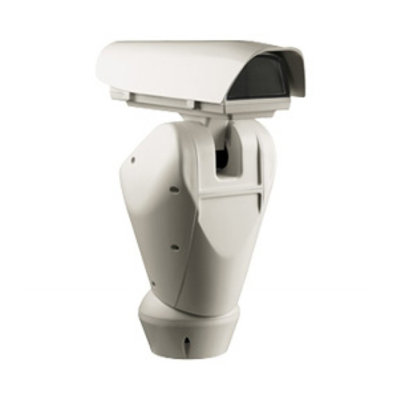
5.2 Essuie-glace intégrée page 43. La tourelle peut être munie d’un essuie-glace. 5.3 Vitre au germanium ULISSE équipé d’une vitre au Germanium, est prévu pour protéger les caméras thermiques des agressions climatiques extérieures. Fig. 02 Pour actionner l’essuie-glace, se référer à "11.7 Validation de l’Essuie-glace (Wiper)", page 52.
6 Préparation du produit 5.4 Caméra Day/Night Intégrée en vue de l’utilisation Disponible en version avec caméra module SONY qui comprend un zoom optique donnant une sensibilité élevée permettant une prise de vue, même en très Toute modification non approuvée faible luminosité.
Contrôler que le contenu correspond à la liste compromettrait le bon fonctionnement du matériel indiquée ci-dessous: système. Il est impératif de ne pas monter la • Unité de positionnement ULISSE tête en bas. • Emballage Accessoires: • Clé six pans Accorder une attention particulière aux...
7 Assemblage et 6.4.1.2 Fixation avec colonne de support (en option) installation Le support permet le passage des câbles de raccordement à l'intérieur. La base peut être fixée au L’assemblage et l’installation doivent support dans 4 différentes positions, orientées à 90° exclusivement être effectués par un l'une par rapport à...
7.1.1.2 Installation de la caméra 7.1.2 Branchement de la caméra et de l'optique motorisée Extraire la glissière interne d'appui (01) en desserrant les vis de fixation (02). Fixer la caméra au moyen 7.1.2.1 Carte de connexions pour l'optique de la vis de 1/4" et régler la glissière interne pour motorisée PTZ positionner correctement le système optique et la Voir plus bas la description de la carte électronique...
7.1.2.2 Connecteur caméra/optiques Effectuer les connexions des potentiomètres comme indiqué sur le schéma suivant. motorisées Tous les branchements illustrés ci-après + POT doivent exclusivement être exécutés par FOCUS des installateurs experts et toutes les IRIS spécifications de câblage et d'alimentation ZOOM des dispositifs doivent être respectées.
7.2 Installation 7.1.2.3 Réglage de la tension d'alimentation des moteurs des optiques 7.2.1 Connexion des câbles à la base Avant d'alimenter la tourelle, programmer la tension d’alimentation des optiques en agissant sur le DIP1. N'effectuer des modifications ou connexions non prévues dans ce manuel: l’utilisation d’appareils inadéquats peut comporter des risques sérieux pour les appareils et la sécurité...
7.2.2 Fixage de la base au support Passer et serrer les câbles dans les presse-câbles en maintenant la base à environ 20cm du support avec Pour la fixation du support, utiliser les vis un couple de 5Nm. Les presse-câbles sont prévus fournies avec la base.
7.2.3 Connexion de la carte de Le câble de terre doit être plus long des deux autres d'environ 10mm pour éviter connexion tout détachement accidentel. Voir plus bas la description de la carte de connexion qui se trouve à l'intérieur de la base de la tourelle. Power Power Fig.
7.2.3.2 Connexion ligne alimentation 24Vac 7.2.4 Connexion du câble vidéo Connecter les câbles d'alimentation comme décrit L'installation est du type CDS (Cable dans le tableau ci-dessous. Distribution System), ne pas la connecter à des circuits SELV. CONNEXION LIGNE ALIMENTATION 24VAC Couleur Bornes Pour réduire les risques d’incendie, utiliser...
7.2.5 Branchement du câble de réseau Ethernet (seulement version Carte IP) Pour le branchement du câble de réseau il faut un câble UTP, Catégorie 5E ou supérieure, 4 couples, longueur maximale 100m. RS232 La transmission de la télémétrie et du signal vidéo passent à...
7.3 Montage de la partie 7.4 Configuration supérieure Avant de mettre l'appareil sous tension, il est nécessaire de le configurer correctement au moyen des dip- La calotte inférieure contient un sachet switches installés derrière le panneau de configuration. de sels déshydratants permettant d'éviter Ouvrir en desserrant les vis comme indiqué...
7.4.2 Configuration de la vitesse de 7.4.4 Configuration adresse transmission en bauds Il est possible de configurer l'adresse de ULISSE de 1 à 255. La sélection de l'adresse s'effectue selon le Les dip-switches 4, 3 et 2 permettent de configurer code binaire au moyen des 8 dip-switches en haut à...
7.4.5.1 Ligne RS485 RX 7.4.5.3 Ligne RS485-1 réception, ligne RS485-2 répétition La ligne RS485-1 fonctionne selon les programmations établies avec les dip-switches Ce type de configuration permet de connecter Adresse, Vitesse De Transmission et Protocole. plusieurs dispositifs en cascade. Le signal est régénéré...
Description DIP 2 DIP 1 Configuration qu'avec l'alimentation coupée. Ligne RS485-1 Terminée Non terminée La marche et l'arrêt des appareils de la série ULISSE Ligne RS485-2 Terminée s'effectue avec l'alimentation. Non terminée La procédure de préchauffage automatique Tab. 11 (De-Ice) peut être activée chaque fois que le dispositif est mis en fonction à...
Lors de la première mise en service, toujours vérifier 9.1 Menu sur écran (OSM) la configuration de l'appareil: Durant le fonctionnement normal de l'ULISSE, il sectionner l'alimentation, retirer le panneau de est possible d'activer le Menu Sur Écran pour la protection des dip-switches et placer le levier du dip- configuration des fonctions avancées au moyen des...
9.2 Comment se déplacer dans le 9.3 Comment modifier les menu configurations Chaque page-écran du OSM présente une liste Se déplacer au moyen du curseur sur le paramètre de paramètres ou de sous-menus pouvant être à modifier et confirmer. Le champ commence à sélectionnés par l'opérateur.
9.4 Comment modifier les 9.5 Comment modifier les textes champs numériques Se déplacer au moyen du curseur sur le paramètre à modifier et confirmer. Se déplacer au moyen du curseur sur le paramètre à modifier et confirmer. MODIFICATION ZONE ------------------------ MODIFIER PRESET 1 NR.
9.6 Configuration du système La commande Confirmer (Zoom Tele) permet d’insérer le caractère désiré. 9.6.1 Menu principal EDIT TEXT: AREA Le menu principal permet d'accéder à la ------------------------ configuration du dispositif. Text: TEXT AREA1 ↑ >A B C D E F G ERASE MENU PRINCIPAL >...
9.6.3 Menu paramètres caméra ZFI TITRAGE DES ZONES 01. Zoom: Programme le nombre maximum ------------------------ 1>NR. d'agrandissements que peut effectuer l'optique 2 ENAB.: motorisée. 3 START: + 0.00 02. Fil commun: Si validé, il gère les optiques 4 STOP : + 0.00 motorisées à...
9.6.3.2 Menu Masquage des Zones Exemple: Pour activer le masquage de la zone 1 quand le dispositif se trouve entre +15° et +45° il Cette fonction permet de configurer un maximum faut: de huit masques (de dimensions variables) et • Programmer 1 comme valeur du paramètre Nr. éventuellement de les titrer.
9.6.4 Menu Communication Sérielle 9.6.5 Menu Polarité Caisson À partir du menu Polarité, il est possible de configurer les paramètres suivants : Après être sorti du OSM de la caméra, 01. Zoom: Permet de configurer la polarité de appuyer sur la touche IRIS CLOSE pour rotation du moteur du Zoom de l'optique.
9.6.6.1 Menu Titrage des zones Exemple: Pour activer le titrage de la zone 1 quand le dispositif se trouve entre +15° et +45°, procéder L’accès au menu Modifier Zone permet de configurer comme suit: les paramètres suivants: 01. Valider le titrage des zones en configurant O 01.
9.6.6.2 Menu Masquage 9.6.6.3 Menu Masquage (Modifier Masques) L’accès au menu Modifier Masques permet de Le masquage dynamique permet de créer un maximum de 24 masques de façon à obscurcir des configurer les paramètres suivants: zones particulières définies par l’utilisateur. 01.
• Au moyen du joystick du pupitre, effectuer un • Un petit rectangle s'affiche. Au moyen du joystick mouvement de l'unité et utiliser si nécessaire le (Pan et Tilt), agrandir le rectangle jusqu'à couvrir zoom pour centrer la fleur sur l'écran. toute la fleur.
9.6.6.6 Menu Configurations Avancées 9.6.6.8 Menu Configurations Avancées (Focus) L’accès à ce menu permet de configurer le module SONY. L’accès au menu Focus permet de configurer les paramètres suivants: 01. Zoom: Permet d’accéder au sous-menu Zoom. 01. Vitesse Focus: Configure la vitesse du Focus. 02.
9.6.6.9 Menu Configurations Avancées Le tableau suivant indique la correspondance entre les valeurs introduites et leur effet sur le système (Exposition) optique du module SONY. Après avoir accédé au menu Exposition il est possible de configurer les paramètres suivants: 01-05. Mode: Configure le type de contrôle de l’exposition Auto, Manual, Shutter, Iris et Bright.
9.6.6.10 Menu Configurations Avancées Pour éviter de fausses commutations nous conseillons de choisir les valeurs de seuil (Infrarouge) et de retard de commutation diurne plus Après avoir accédé au menu Infrarouge il est élevées. possible de configurer les paramètres suivants: 02.
9.6.6.11 Menu Configurations Avancées 9.6.6.12 Menu Configurations Avancées (Équilibre Blanc) (Autre) L’accès au menu Équilibre Blanc permet de 01. Netteté: Configure la valeur de netteté de configurer les paramètres suivants: l’image. 01. Mode: Configure le type de contrôle d’équilibre 02. Haute Resolution: Valide la fonction Haute Resolution.
05. Autopan: Permet d’accéder aux sous-menus de 9.6.7.2 Menu Contrôle Manuel (Limites) modification des valeurs de l’Autopan. Après avoir accédé au menu Limites, il est possible 06. Rappel Mouvements: Permet d’accéder au de configurer les paramètres suivants: sous-menu de gestion du rappel automatique 01.
9.6.7.4 Menu Preset (Modifier Preset) 9.6.7.5 Menu Preset (Utilités Preset) Après avoir accédé au menu Modifier Preset, il est Une fois entré dans le menu Utilités Preset il est possible de configurer les paramètres suivants: possible de configurer les paramètres suivants: 01.
9.6.7.6 Menu Patrol 9.6.7.8 Menu Rappel mouvements 01. Premier Preset: Configure le premier preset de Il est possible de configurer la tourelle de façon à la séquence de Patrol. ce que, après une certaine période d’inactivité, le système effectue automatiquement une fonction de 02.
9.6.8 Menu Affichages 9.6.9 Menu I/O numériques 01. Position Actuelle: Si différente de Off, permet 01. Alarmes: Permet d’accéder au menu Alarmes. de sélectionner le mode d’affichage des 02. Système De Lavage: Permet d’accéder au menu positions de Pan, Tilt, Zoom, Focus et Iris. Système de Lavage.
9.6.9.2 Menu Système de lavage A partir de ces menus, il est possible de programmer les valeurs suivantes: La tourelle offre la possibilité d’utiliser un essuie- 01. Type: Programme le type de contact: glace et d’actionner une pompe pour le nettoyage normalement clos (N.C.) ou normalement ouvert de la glace.
9.7 Configuration Carte IP 9.6.10 Menu par défaut 01. Effacer Setup: Rétablissement de tous les 9.7.1 Conditions essentielles minimales paramètres à l’exception des preset. PC (seulement version avec Carte IP) 02. Effacer Preset: Élimine tous les preset En fonction du nombre de canaux à controler, choisir mémorisés précédemment.
Page 183
Poursuivre en appuyant sur le bouton Install. Pour accéder à l’adresse 192.168.0.100.un login et un mot de passe vous seront demandés. Á la suite, la fenêtre Vidéo Live va s’ouvrir. Le login ( nom de compte) par défault est: Admin écrit avec un A majuscule.
9.7.2.1 Installation WAN Pour la télémétrie laisser les paramètres par défault. Entrer ensuite l’adresse statique, grâce à laquelle vous pourrez accéder à l’unité à configurer. Par exemple, prenez une IP statique à l’adresse 192.168.0.101 Fig. 108 A la fin des différents paramétrages, ne pas oublier d’effectuer un Save &...
Cliquer sur le bouton Setup de la barre de commande. Bouton Setup Fig. 110 Sélectioner la case Videotec NVR Professional et suivre les instructions indiquées dans le programme. Á la la fin de la procédure d’installation, et après Fig. 112 avoir configuré...
Media Source. Camera Model: Sélectionner 1-CH Video Server Sélectionnez la case Enable PTZ. Puis, Appliquer. Le protocole Videotec, de type Macro à 38400 bauds, sera automatiquement programmé. Fig. 114 Inscrire le nom qui apparaîtra sur la liste Camera...
à mémoriser. Aller dans le menu Setup / Setup Camera et sélectionner la fiche PTZ Preset. Sélectionner dans la liste Media Source l’unité désirée (exemple: ULISSE 3) et activer la fonction Live View. Mouse PTZ Fig. 118 Pour programmer les paramètres de configuration de la tourelle à...
10 Accessoires Procéder de la même manière pour les autres unités. Fermer le programme NVR et le relancer 10.1 Système de lavage pour enregistrer les modifications. La tourelle, si elle est munie d’un essuie-glace, peut Á la réouverture, il est possible de rappeler les aussi être équipée d’une pompe externe qui fournit positions paramétrées par la commande Go To sur le l’eau pour le nettoyage de la glace.
Fig. 123 Connecteur Signal de la carte base de la tourelle. Tous les modèles de la série ULISSE PAN/TILT/Z/F/I: La position actuelle de PAN, TILT, sont équipés de cette fonction.
11.2 Sauvegarde de la position 11.6 Rappel de la position de actuelle (Preset) Home A l'aide du dispositif de contrôle utilisé, il est possible Avec un dispositif de contrôle, il est possible de rappeler la position de Home (Scan n.1) (pour plus d’informations, se de sauvegarder la position actuelle (pour de plus amples informations, se référer au manuel du référer au manuel du dispositif de contrôle utilisé).
11.10 Commandes spéciales COMMANDES SPÉCIALES Commande Protocole MACRO PELCO D AMERICAN DYNAMICS VISTA PANASONIC Wiper Start Sauver Preset 85 Sauver Preset 85 Sauver Preset 85 Sauver Preset 85 Sauver Preset 85 Aux 3 ON Aux 3 ON Aux 3 ON Aux 3 ON Sauver Preset 51 Wip+...
12 Entretien et nettoyage 12.2 Nettoyage Les tourelles n'exigent aucun entretien particulier. 12.1 Entretien Pour le nettoyage de l'appareil, utiliser des détergents neutres et des chiffons non abrasifs. Le dispositif est 12.1.1 Remplacement des fusibles imperméable. Procéder exclusivement aux connexions de 12.2.1 Entretiens de la vitre et des la base avec l'alimentation sectionnée et le parties en plastique (PC)
Durant la mise en service, la tourelle reste bloquée et affiche La température ambiante est très basse. une page-écran du type suivant: Attendre la fin de la procédure de préchauffage. Si la température ambiante est trop basse, l'ULISSE reste bloqué et DE-ICE PROCEDURE affiche la page-écran suivante: ------------------------...
Page 194
Le moniteur n'affiche pas l'image filmée par l'ULISSE, mais Dip switch de programmation activé. une page-écran du type suivant: Éteindre la tourelle, abaisser le levier du dip-switch de mise à jour du micrologiciel (dip-switch numéro 1 dans la section INFO baudrate).
VIDEOTEC MACRO) uniquement des câbles de dimensions égales ou supérieures à 26AWG. Affichage alphanumérique de 15 caractères pour titrage zone et preset 15.1 ULISSE 15.1.3.1 Caméra Day/Night intégrée CAMÉRAS DISPONIBLES 15.1.1 Généralités SONY Day/ Fabriqué en fonte d’aluminium et en ABS...
VIDEOTEC. Il est donc possible que les protocoles sont change ou que Résolution 160x120 HxV ce dernier soit modifié par rapport à ceux soumis à essai par VIDEOTEC. VIDEOTEC conseille par conséquent de procéder à un essai avant des zones de toute installation.
15.2.2 Mecanique VIDEOTEC. Il est donc possible que les protocoles sont change ou que ce dernier soit modifié par rapport à ceux soumis à essai par VIDEOTEC. 3 presse-étoupes M16 VIDEOTEC conseille par conséquent de procéder à un essai avant Rotation horizontale continue toute installation.
16 Dessins techniques Les valeurs sont entendues en millimètres. Fig. 126 ULISSE...
Page 199
Fig. 128 ULISSE pour camera thermiques...
Page 200
SURFACE SURFACE SURFACE UTILE UTILE UTILE A - A B - B B - B CHARIOT EN POSITION STANDARD, CHARIOT EN POSITION STANDARD CHAUFFAGE RENFORCÉ SURFACE UTILE SURFACE SURFACE SURFACE UTILE UTILE UTILE C - C D - D D - D CHARIOT RENVERSÉ...
17 Annexe A - Tableau des adresses dip-switch Ci-après, on reporte toutes les combinaisons possibles. Le levier du dip-switch vers le haut représente la valeur 1 (ON) tandis que le levier vers le bas représente la valeur 0 (OFF). SÉRIELS ET ADRESSE, CONFIGURATION ADRESSE DIP 10 DIP 9 DIP 8...
Page 209
Inhaltsverzeichnis DEUTSCH 1 Allgemeines ........................7 1.1 Schreibweisen ................................. 7 2 Anmerkungen zum Copyright und Informationen zu den Handelsmarken .... 7 3 Sichereitsnormen ......................7 4 Identifizierung ......................9 4.1 Beschreibung und Bezeichnung des Produktes ..................9 4.2 Kennzeichnung des Produkts ..........................9 4.2.1 Prüfung der Kennzeichnung ..............................
Page 210
7.3 Montage der oberen Einheit ..........................21 7.4 Konfigurieren .................................21 7.4.1 Konfiguration der Dip-Switch ............................21 7.4.2 Einstellung der Baud Rate ..............................22 7.4.3 Einstellung des Protokolls ..............................22 7.4.4 Einstellung der Adresse ..............................22 7.4.5 Serielle Übertragungsleitungen .............................22 7.4.5.1 Leitung RS485 RX ......................................23 7.4.5.2 Leitung RS422 (RS485-1 RX und RS485-2 TX) ..........................23 7.4.5.3 Leitung RS485-1 Empfang, Leitung RS485-2 Wiederholung .....................23 7.4.5.4 Leitung RS485 TX/RX ....................................23 7.4.6 Das Abschließen serieller Leitungen/Verbindungen ....................24...
Stromversorgung, bevor die beschriebenen bei der Schaffung oder Produktion von Arbeiten durchgeführt werden. diesem Handbuch miteinbezogen ist. GEFAHR! Die zur Baureihe ULISSE gehörenden Heiße Oberfläche. Positionierungssysteme für die Videoüberwachung Nicht berühren. Die Oberflächen sind entsprechen den Vorschriften, die zum Zeitpunkt heiß...
Page 214
• Es dürfen nur Original-Ersatzteile verwendet • Wenn die Einrichtung von der Anlage getrennt werden. Nicht originale Ersatzteile können zu werden muss, ist das Erdungskabel stets zuletzt Bränden, elektrischen Entladungen oder anderen abzuklemmen. Gefahren führen. • Vermeiden Sie durch gebotene Vorkehrungen, • Vor der Installation ist anhand des dass das Gerät durch elektrostatische Entladungen Kennzeichnungsschildes nachzuprüfen, ob das...
Fig. 01 Vertikalachse bei einer Höchstgeschwindigkeit von 40°/s in einem Neigungsbereich zwischen +90° Das Schildchen auf dem Korpus nennt: und -40° liegt. ULISSE arbeitet mit den Funktionen • Identifikationsnummer des Modells (Strichcode Autopan und Patrol; die Erfassungspräzision beträgt Extended 3/9 ) 0.02°...
5.2 Integriertem Scheibenwischer 5.3 Fensterscheibe aus Der Schwenk-Neige-Kopf kann mit einem Scheibenwischer ausgestattet sein. Germanium ULISSE ist mit Germaniumglas ausgestattet, das eigens für Anlagen mit Wärmebildkameras ausgelegt ist. Fig. 02 Zur Betätigung des Scheibenwischers siehe "11.7 Aktivierung Scheibenwischer (Wiper)", Seite 52.
6 Vorbereitung des 5.4 Integrierte Day/Night- Kameramodul Produktes auf den Gebrauch Version mit Modulkamera von SONY erhältlich, die Jede vom Hersteller nicht ausdrücklich einen unglaublichen optischen Zoom besitzt, für eine genehmigte Veränderung führt zum Verfall erhöhte Empfindlichkeit in schlecht beleuchteten der Gewährleistungsrechte.
• Basis für Netzstromversorgung Schachtel: 6.4.1.1 Befestigung mit Halterung • Basis für Netzstromversorgung (Optional) • ULISSE IR Zubehör Schachtel: Die Halterung hat ein Loch zum Durchführen der Anschlusskabel. Die Basis kann in 4 unterschiedlichen • Infrarotscheinwerfer Halterung Stellungen - zueinander um 90° verdreht - an • Schraubensatz für die Befestigung der Halterung...
7 Zusammenbau und 6.4.1.2 Befestigung mit Haltesäule (Optional) Installation Der Pfahl ist mit einer Öffnung versehen, durch die sich bequem die Anschlusskabel führen lassen. Die Zusammenbau und Installation sind Basis kann in 4 unterschiedlichen Positionen - um Fachleuten vorbehalten. 90° zueinander verdreht - am Pfahl befestigt werden, um die Positionierung der Konfigurierungsklappe zu 7.1 Zusammenbau erleichtern.
7.1.1.2 Kamerainstallation 7.1.2 Anschluss der Kamera und der motorisch bewegten Optik Den internen Auflageschlitten (01) herausziehen, indem man die Befestigungsschrauben löst (02). Die Kamera 7.1.2.1 Platine fur motorisch bewegte PTZ mit der Schraube 1/4" fixieren und den Innenschlitten so Optiken einstellen, dass Optik und Kamera korrekt positioniert sind Nachstehend ist die elektronische Platine innerhalb Den verstellbaren Schlitten mit den zugehörigen...
7.1.2.2 Anschluss Kamera / motorisch Anschlüsse der Potentiometer wie im folgenden Schema ausführen. bewegte Optik Alle nachstehend erläuterten Anschlüsse + POT dürfen nur von Fachleuten ausgeführt werden FOCUS und müssen den Anforderungen entsprechen, IRIS die hinsichtlich der Verdrahtung und Speisung ZOOM der Einrichtungen bestehen.
7.2 Installation 7.1.2.3 Regelung der Versorgungsspannung für die Motoren der Optiken 7.2.1 Anschließen der Kabel an die Bevor die Stromversorgung des Schwenk-Neige- Basis Kopfes hergestellt wird, ist die Versorgungsspannung der Optiken mithilfe von DIP1 einzustellen. Unter keinen Umständen dürfen Änderungen oder Anschlüsse vorgenommen werden, die in diesem Handbuch nicht vorgesehen sind.
7.2.2 Befestigung der Basis an der Die Kabel in die Kabelhalter einführen und die Kabelhalter mit einem Anzugsmoment von 5Nm Halterung befestigen, während die Basis etwa 20cm von der Halterung entfernt gehalten wird. Die Kabelhalter Verwenden Sie das zugehörige Kit, das im eignen sich für Kabeldurchmesser zwischen 5 und Lieferumfang der Basis enthalten ist.
7.2.3 Anschluss der Verbinderplatine Das Erdungskabel muss um etwa 10mm länger sein, als die anderen beiden Kabel, Nachstehend ist die Verbinderplatine innerhalb der um das ungewollte Lösen durch Ziehen des S-N-Kopf-Basis beschrieben. Kabels zu verhindern. Power Power Signal RS232 Fig. 27 Fig.
7.2.3.2 Stromversorgung Anschluss 24Vac 7.2.4 Anschluss des Videokabels Die Versorgungskabel sind nach der folgenden Die Anlage gehört zum Typ CDS (Cable Distribution Tabelle anzuschließen. System), nicht an Kreisläufe SELV anschließen. STROMVERSORGUNG ANSCHLUSS 24VAC Zur Senkung der Brandgefahr dürfen nur Farbe Klemmen Kabel benutzt werden, die mindestens der Vom Installierenden zu bestimmen...
Page 226
7.2.5 Anschluss Ethernet-Netzkabel (nur Version IP-Karte) Für den Anschluss des Netzkabels ist ein Kabel UTP, Kategorie 5E oder höher, vierpaarig, Höchstlänge 100m erforderlich. RS232 Die Übertragung der Telemetrie und des Videosignals erfolgt über das Ethernet- Netzkabel. Nicht das Kabel RS485 und das Fig.
7.3 Montage der oberen Einheit 7.4 Konfigurieren Bevor die Einrichtung mit Strom versorgt wird, Im Innern der unteren Haube befindet sich muss sie richtig mit den Dipschaltern innerhalb des ein Beutelchen mit Entfeuchtungssalz, Konfigurierungskläppchens konfiguriert werden. Sie das der Bildung von Feuchtigkeit in der wird durch Entfernen der Schrauben geöffnet, wie in Basis und an den Anschlussplatinen der Abbildung dargestellt:...
7.4.2 Einstellung der Baud Rate 7.4.4 Einstellung der Adresse Die Dipschalter 4, 3 und 2 werden benutzt, um die Als ULISSE-Adressen lassen sich 1 bis 255 vorgeben. Kommunikationsgeschwindigkeit der Einrichtung Die Vorgabe der Adresse erfolgt nach dem Binärcode gemäß der nachstehenden Tabelle vorzugeben.
7.4.5.1 Leitung RS485 RX 7.4.5.3 Leitung RS485-1 Empfang, Leitung RS485-2 Wiederholung Die Leitung RS485-1 arbeitet mit den Einstellungen, die mit Hilfe der Dipschalter Adresse, Baudrate und Bei dieser Einstellung können mehrere Einrichtungen Protokoll vorgegeben werden. kaskadiert angeschlossen werden. Das Signal wird von jeder Einheit regeneriert und ist dadurch über Die serielle Leitung RS485-2 wird nicht benutzt.
DIP 2 DIP 1 Konfiguration und zuverlässig befestigt sind. Leitung RS485-1 Abgeschlossen Nicht abgeschlossen Die Systeme der Baureihe ULISSE schalten sich ganz Leitung RS485-2 Abgeschlossen einfach mit Aufnahme der Stromversorgung ein und Nicht abgeschlossen mit Unterbrechung der Stromversorgung aus. Tab. 11 Der automatische Vorheizvorgang (de-ice) könnte immer dann aktiviert werden, wenn...
Beim erstmaligen Einschalten ist es stets Während des normalen Betriebes der Einrichtung zweckmäßig, die korrekte Konfiguration der ULISSE kann das Bildschirmmenü aktiviert werden, Einrichtung zu überprüfen. um die erweiterten Funktionen mit der / den Dazu ist es notwendig, die Stromversorgung entsprechenden Taste(n) einzurichten (siehe hierzu zu unterbrechen.
9.2 Das Bewegen innerhalb der 9.3 Änderung der Einstellungen Menüs Den Cursor auf den zu ändernden Parameter bewegen und bestätigen. Das Feld beginnt zu Jeder OSM-Bildschirm weist eine Liste mit Parametern blinken als Zeichen dafür, dass es geändert wird. oder Untermenüs auf, die vom Bediener angewählt Durch Bedienung des Steuerknüppels (auf und ab) werden können.
9.4 Ändern der Zahlenfelder 9.5 Ändern von Texten Den Cursor auf den zu ändernden Parameter Den Cursor auf den zu ändernden Parameter bewegen und bestätigen. bewegen und bestätigen. PRESET ANDERN ZONE ANDERN ------------------------ ------------------------ 1 NR. 1 NR. 2 ENAB.: 2 START:+ 0.00 3>PAN...
9.6 Systemkonfigurierung Mit dem Befehl Bestätigen (Zoom Tele) wird das gewünschte Zeichen eingefügt. 9.6.1 Hauptmenü EDIT TEXT: AREA Vom Hauptmenü aus kann die Konfigurierung der ------------------------ Einrichtung aufgerufen werden. Text: TEXT AREA1 ↑ >A B C D E F G ERASE HAUPTMENU H I J K L M N...
9.6.3 Parametermenü Kamera ZFI ZONENBETITELUNG 01. Zoom: Einstellbar ist die maximale ------------------------ 1>NR. Vergrößerungszahl, welche die motorisierte 2 ENAB.: Optik leisten kann. 3 START: + 0.00 02. Gemeinsamer Draht: Wird diese Option 4 STOP : + 0.00 aktiviert, werden die motorisierten Optiken mit 5 TEXT : ZONE 1 gemeinsamem Draht gesteuert, andernfalls die Optiken mit Polaritätsumkehr.
9.6.3.2 Menü Zonenmaskierung Beispiel: Zur Aktivierung der Maskierung von Zone 1, wenn sich die Vorrichtung zwischen +15° und +45° Diese Funktion gestattet die Festlegung von bis zu befindet wie folgt vorgehen: acht Masken (verschiedener Größe), die sich betiteln • Den Parameter Nr auf den Wert 1 setzen. lassen.
9.6.4 Menü Gehäuse seriell 9.6.5 Menü Polarität Im Menü Polarität können die folgenden Parameter Nachdem das OSM der Kamera verlassen festgelegt werden: worden ist, die Taste IRIS CLOSE drücken, um zum OSM des Schwenk-Neige-Kopfes 01. Zoom: Hier kann die Polarität festgelegt werden, zurückzukehren.
9.6.6.1 Menü Zonenbetitelung Beispiel: Um die Betitelung der Zone 1 zu aktivieren, wenn sich die Vorrichtung zwischen +15° und +45° Im Menü Zone Ändern können die folgenden befindet, ist folgendermaßen vorzugehen: Parameter festgelegt werden: 01. Die Zonenbetitelung aktivieren, indem man 01.
9.6.6.2 Menü Maskierung 9.6.6.3 Menü Maskierung (Masken Ändern) Nach dem Aufruf des Menüs Masken Ändern Die dynamische Maskierung ermöglicht die Vorgabe von bis zu 24 Masken, mit denen besondere können die folgenden Parameter eingestellt werden: benutzerdefinierte Bereiche verdunkelt werden. 01. Maskennummer: Zur Auswahl der zu Die Masken werden im Raum definiert und ändernden Maske.
• Mit dem Steuerknüppel der Bedientastatur die • Es erscheint ein kleines Rechteck. Mit dem Vorrichtung bewegen und bei Bedarf zoomen, bis Steuerknüppel (Pan und Tilt) das Rechteck die Blume auf dem Bildschirm zentriert ist. vergrößern, bis die gesamte Blume verdeckt ist. MASK 1 MASK 1 PTZ Bewegung ON...
9.6.6.6 Menü Erweitert Konfiguriert 9.6.6.8 Menü Erweitert Konfiguriert (Focus) Im Menü Focus lassen sich die folgenden Parameter Mit diesem Menü kann das Modul von SONY konfiguriert werden. festlegen: 01. Zoom: Aufruf des Untermenüs Zoom. 01. Focus-Geschwindigkeit: Einstellbar ist hier die Focusgeschwindigkeit. Die 02.
9.6.6.9 Menü Erweitert Konfiguriert In der folgenden Tabelle sind die Entsprechungen zwischen den eingegebenen Werten und (Belichtung) der Wirkung auf die Optik des SONY-Moduls Nach dem Aufruf des Menüs Belichtung können die zusammengestellt. folgenden Parameter festgelegt werden: 01-05. Modus: Art der Belichtungssteuerung - Auto, Manual, Shutter, Iris und Bright.
9.6.6.10 Menü Erweitert Konfiguriert Um falsche Schaltungen zu vermeiden ist es ratsam, die höchsten Werte sowohl für (Infrarot) die Schwelle als auch die Verzögerung der Im Menü Infrarot können die folgenden Parameter Tagschaltung auszuwählen. festgelegt werden: 02. IR-Modus: Wird hier Off eingestellt, INFRAROT ist dauerhaft der Tagesmodus aktiviert ------------------------...
9.6.6.11 Menü Erweitert Konfiguriert 9.6.6.12 Menü Erweitert Konfiguriert (Anderen) (Weißabgleich) 01. Sharfe: Einstellung der Bildschärfe. Nach dem Aufruf des Menüs Weißabgleich können die 02. Hohe Auflosung: Zum Einschalten der Funktion folgenden Parameter festgelegt werden: Hohe Auflosung. Das ausgehende Videosignal hat eine höhere Auflösung. 01.
04. Patrol: Ermöglicht den Aufruf der Untermenüs, 9.6.7.2 Menü Handsteuerung (Grenzpunkte) welche die Änderung der Patrolwerte ermöglichen. Im Menü Grenzpunkte lassen sich die folgenden 05. Autopan: Ermöglicht den Aufruf der Untermenüs Parameter festlegen: für die Änderung der Autopanwerte. 01. Grenzpunkte Pan: Aktiviert die Grenzpunkte für 06.
08. Wechseln Zu Preset: Der Schwenk-Neige-Kopf 04. Ramp Type: The Ramp parameter is used to wird angewiesen, zur ausgewählten Position change start and stop times for the ULISSE. The Preset zu wechseln. higher the number, the greater the acceleration/ 09. Bewegungen Aktivieren: Diese Funktion deceleration during starting/stopping.
9.6.7.6 Menü Patrol 9.6.7.8 Menü Bewegungsanforderung 01. Erstes Preset: Erste Vorwahlposition der Der S-N-Kopf kann so eingestellt werden, dass die Patrolsequenz. Einrichtung nach einer bestimmten Inaktivitätsdauer automatisch eine vom Bediener vorgegebene 02. Letzes Preset: Letzte Vorwahlposition der Bewegungsfunktion ausführt. Patrolsequenz. Im Menü...
9.6.8 Menü Anzeigen 9.6.9 Menü I/O digital 01. Aktuelle Position: Wenn die Einstellung nicht 01. Alarme: Gestattet den Zugriff auf das auf Off lautet, kann gewählt werden, wie auf Alarmmenü. dem Bildschirm die Positionen Pan, Tilt, Zoom, 02. Waschanlage: Gestattet den Zugriff auf das Focus und Iris angezeigt werden.
9.6.9.2 Menü Waschanlage In diesem Menü können die folgenden Werte vorgegeben werden: ULISSE COMPACT bietet die Möglichkeit, einen 01. Art: Eingestellt wird die Kontaktart: Scheibenwischer einzusetzen und eine Pumpe für die Normalerweise geschlossen (NC) oder Scheibenreinigung zu betätigen. normalerweise geöffnet (NO) Zur Einstellung der Waschanlage das Kameraobjektiv 02.
9.7 Konfiguration IP-Karte 9.6.10 Menü Default 01. Setup löschen: Versetzt alle Parameter außer 9.7.1 Mindestanforderungen an den PC die Presetparameter in den ursprünglichen (nur Version mit IP-Karte) Zustand. Abhängig von der Zahl der zu steuernden Kanäle ist 02. Preset löschen: Löscht alle gespeicherten eine der folgenden Konfigurationen zu wählen.
Page 251
Die Adresse 192.168.0.100 aufrufen. Es ist eine Fahren Sie fort mit der Betätigung der Schaltfläche Anmeldung und eine Kennworteingabe erforderlich. Install. Das werkseitig vorgegebene Benutzerkonto lautet: Anschließend erscheint das Fenster “Live-Video”. Admin (mit großem A geschrieben). Das werkseitig vorgegebene Kennwort lautet: 123456 Bei der erstmaligen Einrichtung sind dieses Standardbenutzerkonto und Standardkennwort...
9.7.2.1 WAN Konfigurierung Für die Telemetrie lassen Sie bitte die Anfangseinstellungen unverändert. Nun die statische IP-Adresse einrichten, unter der auf die zu konfigurierende Einheit zugegriffen wird. Beispielsweise ein statisches IP und eine Adresse von 192.168.0.101 vorgeben. Fig. 108 Nach Vornahme der einzelnen Einstellungen denken Sie daran, ein Save &...
Einrichtungen der Anlage hinzugefügt werden. Klicken Sie in der Befehlsleiste die Schaltfläche Setup Setup Drucknopf Fig. 110 Die Option Videotec NVR Professional auswählen und den Anweisungen des Programms folgen. Nach Beendigugn des Installationsvorgangs Fig. 112 und nach der sachgerechten Konfigurierung der Dann Setup Camera anklicken.
Media Source auswählen, die konfiguriert werden soll. Das Kästchen Enable PTZ markieren. Dann den Befehl Apply anklicken. Auf diese Weise wird automatisch das Videotec-Protokoll Macro mit 38400 baud eingestellt. Fig. 114 Geben Sie den Namen vor, der später im Verzeichnis...
Position bewegen zu können. Öffnen Sie das Menü Setup / Setup Camera, dort die Registerkarte PTZ Preset wählen. In der Liste Media Source die gewünschte Einheit auswählen (Beispiel ULISSE 3) und die Funktion Live View aktivieren. Mouse PTZ Fig. 118...
10 Zubehör Auf dieselbe Weise die Presetpositonen der anderen Einheiten einstellen. 10.1 Waschanlage Das Programm NVR schließen und neu starten, damit die Einstellungen wirksam Ist der Schwenk-Neige-Kopf mit Scheibenwischer werden. versehen, kann er auch eine externe Pumpe besitzen, die Wasser für die Reinigung der Scheibe heranführt. Beim nächsten Neustart können die vorgegebenen Positonen mit dem Befehl Go To auf der Wie in der Abbildung gezeigt, befindet sich die...
Fig. 123 Signal- Steckverbinder der Grundplatine E1 PATROL CONFIGURATION: Das folgende Feld des S-N-Kopfes. Alle Modelle der Serie zeigt die während des Systembetriebs gefundenen ULISSE verfügen über diese Funktion. Fehler Im Schaltbild sind verzeichnet: PAN/TILT/Z/F/I: Die aktuelle Position von PAN, TILT, • AL1 - COM: Alarmeingang zur Prüfung des...
11.2 Speicherung der aktuellen 11.6 Aufruf der Homeposition Position (Preset) Mithilfe des Kontrollgerätes kann die Home- position aufgerufen werden (Scan Nr.1) (für weitere Informationen Mithilfe der verwendeten Steuerungseinrichtung siehe das Handbuch des verwendeten Kontrollgerätes). lässt sich die Istposition speichern (weitere 11.7 Aktivierung Informationen enthält das Handbuch der verwendeten Einrichtung).
11.10 Spezialbefehle SPEZIALBEFEHLE Befehl Protokoll MACRO PELCO D AMERICAN DYNAMICS VISTA PANASONIC Wiper Start Preset 85- speichern Preset 85- speichern Preset 85- speichern Preset 85- speichern Preset 85- speichern Aux 3 ON Aux 3 ON Aux 3 ON Aux 3 ON Preset 54- speichern Wip+ Wiper Stop...
12 Wartung und Reinigung 12.2 Reinigung Die Schwenk-Neige-Köpfe bedürfen keiner aufwendigen 12.1 Wartung Wartung. Für die Reinigung des Gerätes Neutralreiniger und nicht schleifende Tücher benutzen. Es sei daran 12.1.1 Austausch der Schmelzsicherungen erinnert, dass die Einrichtung wasserundurchlässig ist. Die Basis darf ausschließlich bei unterbrochener 12.2.1 Reinigung des Glases und der Stromversorgung und bei geöffneter Kunststoffteile (PC)
Die Kameraposition mit Hilfe des Schlittens korrekt einstellen. Beim Einschalten bleibt die S-N-Kopf blockiert, die folgende Die Umgebungs-temperatur ist sehr niedrig. Bildschirmseite erscheint: Ende des Vorheizvorgangs abwarten. Wenn die Umgebungs- temperatur zu niedrig ist, blockiert die ULISSE und zeigt den DE-ICE PROCEDURE folgenden Bildschirm: ------------------------ SYSTEM BLOCKED...
Page 262
Auf dem Monitor wird das von der ULISSE aufgenommene Bild Nicht Programmier-Dipschalter aktiv. angezeigt, sondern ein Bildschirm mit dem folgenden Aussehen: Den Schwenk-Neige-Kopf ausschalten, den Kipphebel des Dipschalters der Firmware Aktualisierung absenken (Dipschalter 1 im INFO Abschnitt Baudrate). Das Gerät wieder einschalten.
Maximale Anzahl an Preset- Positionen: 250 (Protokoll VIDEOTEC MACRO) Kabel benutzt werden, die mindestens der Größe 26AWG entsprechen. Kette aus 15 Zeichen für die Betitelung des Bereiches oder der Presets 15.1 ULISSE 15.1.4 Integrierte Day/Night Kameramodul 15.1.1 Allgemeines VERFÜGBARE KAMERAS Konstruktion aus Aluminiumdruckguß und ABS...
Höchstzahl der Die Einheit kann über Schnittstellen mit Produkten verbunden werden, anzeigbaren die nicht von VIDEOTEC produziert sind. Es ist möglich, dass die Protokolle Maskierungsblöcke sich geändert haben oder die in einer anderen Konfiguration von früher von VIDEOTEC getesteten Einheiten sind. Deshalb empfiehlt VIDEOTEC Auflösung der...
3 Kabelschellen M16 Rundum-Schwenk Die Einheit kann über Schnittstellen mit Produkten verbunden werden, die nicht von VIDEOTEC produziert sind. Es ist möglich, dass die Protokolle Neigung von -90° bis +40° sich geändert haben oder die in einer anderen Konfiguration von früher von VIDEOTEC getesteten Einheiten sind.
Page 268
NUTZ- NUTZ- NUTZFLÄCHE FLÄCHE FLÄCHE A - A B - B B - B SCHLITTEN IN STANDARD POSITION, SCHLITTEN IN STANDARD POSITION VERSTÄRKTE HEIZUNG NUTZFLÄCHE NUTZ- NUTZ- NUTZFLÄCHE FLÄCHE FLÄCHE C - C D - D D - D UMGEKEHERTEN SCHLITTEN UMGEKEHERTEN SCHLITTEN, VERSTÄRKTE HEIZUNG NUTZFLÄCHE...
Page 269
17 Anhang A - Tabelle Adressen Dipschalter Nachstehend sind alle Kombinationsmöglichkeiten aufgelistet. Der nach oben zeigende Kipphebel des Dipschalters steht für den Wert 1 (ON), ein nach unten umgelegter Hebel steht für den Wert 0 (OFF). SERIELLE LEITUNGEN UND ADRESSE, ADRESSEKONFIGURATION DIP 10 DIP 9 DIP 8...