Table des Matières
Publicité
Les langues disponibles
Les langues disponibles
Liens rapides
Publicité
Chapitres
Table des Matières
Dépannage

Manuels Connexes pour Videotec ULISSE MAXI


Sommaire des Matières pour Videotec ULISSE MAXI
- Page 1 ULISSE MAXI PTZ unit for dynamic monitoring of large outdoor areas English - Instructions manual Italiano - Manuale di istruzioni Français - Manuel d’instructions Deutsch - Bedienungslanleitung Русский - Руководство по эксплуатации...
- Page 3 ENGLISH ULISSE MAXI PTZ unit for dynamic monitoring of large outdoor areas English - Instructions manual...
-
Page 5: Table Des Matières
Contents E N G L I S H 1 About this manual ......................7 1.1 Typographical conventions ..........................7 2 Notes on copyright and information on trademarks ..........7 3 Safety rules........................7 4 Identification ........................ 10 4.1 Product description and type designation....................10 4.2 Product markings ..............................10 4.2.1 Checking the markings ...............................10 5 Versions ........................ - Page 6 8.6 Fixing the upper body ............................27 8.7 Counterweights installation ..........................27 8.8 LED illuminators installation ..........................28 8.8.1 Counterweight removal ..............................28 8.8.2 Fitting the illuminator on the bracket ..........................28 8.9 Connection of the LED illuminators ........................29 8.10 Connection for cameras and LED illuminators synchronisation ............30 8.11 Desiccant bag ...............................30 8.12 LED illuminator activation and adjustment instructions ..............30 8.12.1 Description of the LED illuminator ..........................30...
- Page 7 10.1.8.2 Manual Control Menu (Limits) ................................47 10.1.8.3 Preset Menu .......................................47 10.1.8.4 Preset Menu (Edit Preset) ..................................47 10.1.8.5 Preset Menu (Utility Preset) ..................................48 10.1.8.6 Patrol Menu ........................................48 10.1.8.7 Autopan Menu ......................................48 10.1.8.8 Motion Recall Menu ....................................49 10.1.9 Display Menu ..................................49 10.1.10 Digital I/O-Options Menu ..............................49 10.1.10.1 Alarms Menu ......................................50 10.1.10.2 Communication menu ..................................50 10.1.10.3 Washer Menu ......................................51...
- Page 8 17.5 Video ..................................62 17.6 Communications ..............................62 17.7 Protocols .................................62 17.8 I/O interface ................................62 17.9 Lenses ..................................62 17.10 Environment ...............................62 17.11 Certifications ..............................62 18 Technical drawings ....................63 A Appendix - Address table ................... 66 MNVCUPTMAXB_1511_EN...
-
Page 9: About This Manual
1 About this manual 3 Safety rules Read all the documentation supplied carefully before CAUTION! The electrical system to which installing and using this unit. Keep the manual in a the unit is connected must be equipped convenient place for future reference. with a 20A max automatic bipolar circuit breaker. - Page 10 • Before starting any operation, make sure the • This device was designed to be permanently power supply is disconnected. secured and connected on a building or on a suitable structure. The device must be permanently • Be careful not to use cables that seem worn or old. secured and connected before any operation.
- Page 11 • Do not allow children or unauthorised people to • Take all necessary precautions to prevent the use the appliance. apparatus from being damaged by electrostatic discharge. • Only skilled personnel should carry out maintenance on the device. When carrying out •...
-
Page 12: Identification
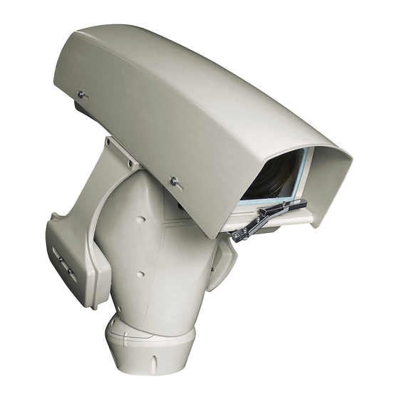
4.1 Product description and type Pan & tilt devices have a label complying with CE markings. designation ULISSE MAXI is a robust and efficient PTZ camera unit designed to ensure dynamic and non-stop surveillance of large outdoor areas and withstand harsh weather conditions. -
Page 13: Versions
The version with LED illuminators can only powered at 24Vac. The pan & tilt can be fitted with bracket for 2 VIDEOTEC LED illuminators for night surveillance (illuminators not included). Fig. 3 Fig. 2 For further information refer to the relative chapter (8.8 LED illuminators installation,... -
Page 14: Preparing The Product For Use
6 Preparing the product for 6.3 Contents Check the contents to make sure they correspond with the list of materials as below: Any change that is not expressly approved • Positioning unit by the manufacturer will invalidate the • Power supply base guarantee. -
Page 15: Preparatory Work Before Installation
6.5 Preparatory work before 6.5.2 Cables management installation The connection cables should not be accessible from the outside. It is necessary 6.5.1 Attaching the bracket to fasten the cables securely to the support in order to prevent excessive weight pulling For installations subject to vibrations, only them out accidentaly. -
Page 16: Assembly
7 Assembly 7.3 Assembling the camera and motorised lenses 7.1 Fixing the sunshield The customer has to take care of assembling the Mount the sunshield to the housing with the 4 screws camera and lenses. and 4 washers couples provided. 7.3.1 Cameras features The correct operation of the equipment, within the temperature range indicated, is... -
Page 17: Fastening The Lens And The Camera To The Internal Slide
7.3.2 Fastening the lens and the camera If necessary, use the additional spacers to correctly position the camera and lens. to the internal slide It is necessary to insulate the camera body from the attachment slide in order to prevent interference with the video signal. Maximum overall weight allowed for camera and lens must not exceed 7.6kg (16.8lb). -
Page 18: Positioning Of The H-20 Spacer On The Inner Slide
7.3.3 Positioning of the H-20 spacer on 7.3.4 Internal slide the inner slide Shift the inner slide with lens and camera already fastened into the wanted position and secure it by It is possible to fasten the H-20 spacer (02) to the lens. means of the washers and screws provided. -
Page 19: Housing Board Description
7.4 Housing board description 7.4.1 Connection of the camera and motorised lens BOARD DESCRIPTION All connections illustrated below should Connector/Terminal Function be made only and exclusively by expert BNC connector, video signal from the installers who should comply with all the camera wiring and power supply specifications for Motorised lens motor control... -
Page 20: Adjustment Of The Supply Voltage Of The Lens Motors
Lenses with reverse polarity motors: Implement Camera: Implement the connections, as shown in the connections, as shown in the figure.. the figure.. FOCUS + 232 TX FOCUS - 232 RX IRIS + IRIS - 485_B ZOOM + 485_A ZOOM - Serial S_GND Video... -
Page 21: Installation
8 Installation 8.1 Connecting the cables to the base Never, under any circumstances, make any changes or connections that are not Insert the cables into the cable glands holding the shown in this handbook. Failure to follow base at about 20cm from the support. Tighten the the connection instructions that are given cable glands. -
Page 22: Fixing The Base To The Support
8.2 Fixing the base to the support Align the 3 notches on the base with those on the support as shown in the following figure. Use the screws and the washers supplied with the base. Once you have positioned the gasket (01), fix the base (02) onto the bracket (03) with screws (04), serrated washers (05) and screw rings (06). -
Page 23: Connector Board Description
8.3 Connector board description CONNECTOR BOARD DESCRIPTION Connector/ Function CONNECTOR BOARD DESCRIPTION Component Connector/ Function Board power supply Component Signal cables Board power supply RS-232 Signal cables Fuse RS-232 Fuse Fuse Tab. 6 Version with LED illuminators. Fuse Tab. 5 Standard version. -
Page 24: Connection Of The Power Supply Line
8.4 Connection of the power Earth cable should be about 10mm longer supply line than the other two, so that it will not be disconnected accidentally if pulled. Depending on the version, the device can be provided with different power supply voltages. The The power supply cable must be covered power supply voltage is indicated on the product by the silicone sheath (01) supplied. -
Page 25: 24Vac Power Line Connection
8.4.1 24Vac power line connection 8.4.2 120Vac and 230Vac power line connection Cut the cables to the correct length and make the connections. Connect the power supply to the Cut the cables to the correct length and make the terminal: J6. connections. -
Page 26: Signal Cable Connection
8.5 Signal cable connection Connect the screen and central cable respectively to the GND and VIDEO All signal cables must be grouped together terminals. The terminals accept cables with by means of a strap. sections between 0.5mm² (20 AWG) and 0.08mm²... -
Page 27: Telemetry Lines Connections
8.5.2 Telemetry lines connections CAUTION! TNV-1 installation type. The installation is type TNV-1, do not connect it to SELV circuits. CAUTION! In order to reduce the risk of fire, only use UL Listed or CSA certified cables with sections greater than or equal to 0.14mm²... -
Page 28: Connection Of The Alarm Inputs, Of The Twilight Switch And Of The Relays
8.5.3 Connection of the alarm inputs, of Version with LED illuminators the twilight switch and of the relays CAUTION! TNV-1 installation type. The installation is type TNV-1, do not connect it to SELV circuits. CAUTION! In order to reduce the risk of fire, only use UL Listed or CSA certified cables AL1 AL2 LNO with sections greater than or equal to... -
Page 29: Fixing The Upper Body
8.6 Fixing the upper body 8.7 Counterweights installation Fix the upper body (01) to the base (02) using the Fasten the counterweights to the housing using the fixing screws (03) equipped with gaskets (04). Make screws and washers supplied. sure the base seal is present and in good condition (05). -
Page 30: Led Illuminators Installation
Place the fixings of the illuminator (01) on those of the bracket (02). To work properly both illuminators must be installed together. From Pan & Tilt, it is only possible to install VIDEOTEC illuminators. 8.8.1 Counterweight removal Undo the screws and remove the external counterweights. Fig. 48 Tighten the screws and the washers previously removed. -
Page 31: Connection Of The Led Illuminators
8.9 Connection of the LED Connect the cables as shown in figure. illuminators Remove the 2 M12 caps. Tighten the 2 cable glands and relative O-rings supplied. Left illuminator Right illuminator Fig. 53 CONNECTION OF THE LED ILLUMINATORS Fig. 50 Left illuminator Right illuminator To ensure the safety and the correct... -
Page 32: Connection For Cameras And Led Illuminators Synchronisation
8.10 Connection for cameras and 8.12 LED illuminator activation LED illuminators synchronisation and adjustment instructions ZFI cameras fitted with infrared filter: Connect Once the adjustment is done the illuminator on the camera’s Day/Night mode switching input to the left (MASTER) synchronizes and controls the the Night Mode connector (dry contact) as shown in illuminator on the right (SLAVE). -
Page 33: Activation Of The Led Illuminator Via An External Dusk Switch
8.12.2 Activation of the LED illuminator 8.12.3 Activation of the LED illuminator via an external dusk switch via the integrated dusk sensor Perform the following operations: To synchronise the unit with the LED illuminators it is necessary to: • Connect the twilight switch to the terminals: LNO/ AGND (8.5.3 Connection of the alarm inputs, of the •... -
Page 34: Led Illuminator Switching On Threshold Adjustment
8.12.4 LED illuminator switching on 8.12.5 LED illuminator power threshold adjustment adjustment The illuminator on the right must always be The illuminator on the right must always be set to maximum brightness. set to minimum power. The illuminator is set in the factory to provide maximum power. -
Page 35: Fastening Of The Wiper Blade
8.13 Fastening of the wiper blade Fasten the whole assembly by means of the washer and nut. Insert the blade on the wiper shaft. Position the blade in the stop position. Fig. 64 The correct adjustment must allow the return of the blade to the stop position Fig. -
Page 36: Hardware Configuration
OFF OFF OFF OFF ON DYNAMICS VISTA OFF OFF OFF ON OFF OFF ON Tab. 13 Deafult configuration: MACRO (VIDEOTEC), 115200 Fig. 67 baud, Address 1. This option does not require the setting of the DIP-switch (DIP1, DIP3). Tab. 14 MNVCUPTMAXB_1511_EN... -
Page 37: Dip3 Configuration
8.14.4 DIP3 configuration 8.14.5 DIP4 configuration When the switch rocker is up it represents This DIP is set following the inverse the value 1 (ON). When the dip-switch procedure compared to those previously rocker is down it represents the value 0 performed. -
Page 38: Installation Examples
RS-485-1 RS-485-2 TX/RX Fig. 75 Fig. 73 This function is only available for bi- directional protocols (example: PELCO, This function is only available for bi- AMERICAN DYNAMICS, VIDEOTEC MACRO, directional protocols (example: PELCO, etc.). AMERICAN DYNAMICS, VIDEOTEC MACRO, etc.). MNVCUPTMAXB_1511_EN... -
Page 39: Switching On
9 Switching on 9.1 First start-up The first time the device is switched on we Make sure that the unit and other recommend making sure it is configured correctly. components of the installation are closed Before providing power supply, remove the DIP so that it is impossible to come into contact protection doors and position the firmware update with live parts. -
Page 40: Configuration
10 Configuration 10.1.1.1 How to use the joystick All operations in the menus are carried out using the 10.1 OSM interface (On Screen joystick. Menu) 10.1.1 Using the OSM During normal operation of the unit, you can activate Left Right the OSM to select and configure advanced functions.. -
Page 41: How To Move Around The Menus
10.1.1.2 How to move around the menus 10.1.1.3 How to modify the parameters Each page of the OSM shows a list of parameters Move the cursor to the parameter to be changed and or sub-menus that can be selected by the operator. confirm. -
Page 42: How To Change The Numeric Fields
10.1.1.4 How to change the numeric fields 10.1.1.5 How to change text Move the cursor to the parameter to be changed and Move the cursor to the parameter to be changed and confirm. confirm. EDIT PRESET EDIT ZONE ------------------------ ------------------------ 1 NR. - Page 43 You can move inside the menu using the joystick. Use: • ERASE: Delete the whole text string. EDIT TEXT: AREA • SAVE: Save the new text before exiting the menu. ------------------------ • EXIT: Exit the menu. Text: TEXT AREA1 ↑ •...
-
Page 44: Configuration Via Osm
10.1.2 Configuration via OSM 10.1.5 ZFI Parameter Menu The screens for configuring the product are Zoom: This sets the maximum zoom level that illustrated below. the motorised lens can achieve. Common Wire: If enabled, it manages the 10.1.3 Main Menu motorised common wire lenses;... -
Page 45: Zone Titling Menu
10.1.5.1 Zone Titling Menu Example: To enable titling of zone 1 when the device is between +15° and +45°, it is necessary to: This function allows setting up to eight (variable • Enable area titling by setting Y as the value of dimension) areas with titling option. -
Page 46: Zone Masking Menu
10.1.5.2 Zone Masking Menu Example: To enable masking of zone 1 when the device is in the +15° and +45° position, proceed as This function allows setting up to eight masks follows: (variable dimension) with titling option. • Select 1 as value of parameter No. Number: Selects the area to be edited. -
Page 47: Housing Serial Port Menu
10.1.6 Housing Serial Port Menu 10.1.7 Polarity Menu It allows you to configure the following parameters: Once you have exited from the camera Zoom: It allows you to choose the motor OSM, press the Iris Close key to return to rotation polarity of the lens Zoom. -
Page 48: Movement Menu
10.1.8 Movement Menu 10.1.8.1 Manual Control Menu Maximum Speed: Select the maximum manual Offset Pan: The pan & tilt has a mechanically speed. defined 0° position. The Offset Pan function allows the definition of a different 0° position Speed With Zoom: When enabled, this using software. -
Page 49: Manual Control Menu (Limits)
10.1.8.2 Manual Control Menu (Limits) 10.1.8.4 Preset Menu (Edit Preset) It allows you to configure the following parameters: It allows you to configure the following parameters: Pan Limits: Enables the limits of Pan. Number: The Preset number to be edited. Pan Start: Sets the start limit of Pan. -
Page 50: Preset Menu (Utility Preset)
10.1.8.5 Preset Menu (Utility Preset) 10.1.8.6 Patrol Menu It allows you to configure the following parameters: First Preset: First preset of the Patrol sequence. Scan Speed: Speed used to reach the Preset Last Preset: Last preset of the Patrol sequence. position after reception of a Scan control. -
Page 51: Motion Recall Menu
10.1.8.8 Motion Recall Menu Received Commands: If enabled, it shows the received serial commands. The unit can be configured so that, after a period of Horizontal Delta: Horizontal displacement of non-use, it carries out a movement function selected the menu texts to improve centring. by the operator. -
Page 52: Alarms Menu
10.1.10.1 Alarms Menu This is a dynamic self-configuration menu based on the choice made and shows the parameters on which 01-04. Alarms 1-4: Access the menus, which it is possible to operate. allow you to modify the Alarm parameters from The Alarm Status menu shows the input status of the 1 to 4. -
Page 53: Washer Menu
10.1.10.3 Washer Menu 10.1.11 Default Menu The unit offers the possibility to use a wiper and to Delete Setup?: Resets all the parameters except operate a pump to clean the glass. the Presets. To configure the Washer put the lens of the camera in Delete Preset?: Deletes all previously stored front of the nozzle of the Washer. -
Page 54: Accessories
11 Accessories 11.1.1 Washing system connection CAUTION! TNV-1 installation type. The For further details on configuration and installation is type TNV-1, do not connect it use, refer to the relative manual. to SELV circuits. 11.1 Washer CAUTION! In order to reduce the risk of fire, only use UL Listed or CSA certified cables The P&T can be equipped with an external pump that with sections greater than or equal to... -
Page 55: Wall Mount Bracket
11.2 Wall mount bracket 11.4 Power supply with illuminator control Wall bracket with internal cable channel. Weather-proof box with power supply and control of the illuminators. Fig. 120 Fig. 122 Version of the standard box. 11.3 Parapet bracket Parapet bracket with internal cable channel. Fig. -
Page 56: Instructions For Normal Operation
12 Instructions for normal 12.2 Saving a Preset operation The current position can be saved using the control device being used (for additional information refer to 12.1 Visualizing the state of the the manual of the device being used). 12.3 Restore a Preset position pan &... -
Page 57: Autopan Enabling
12.6 Autopan enabling 12.8 Enabling the washer (Washer) The Autopan function loads the 2 saved Presets in a continuous manner. When a control is provided, the Pan & Tilt is To activate/deactivate this function, refer to the positioned with the window in front of the nozzle.. manual of the control device used or to the relative The pump and wiper are activated for a set period of chapter (12.11 Special controls, page 56). -
Page 58: Special Controls
12.11 Special controls SPECIAL CONTROLS Action Control Protocol AMERICAN ERNITEC PANASONIC PELCO D VIDEOTEC VISTA DYNAMICS MACRO Wiper Start Save Preset 85 Save Preset 85 Save Preset 85 Save Preset 85 Save Preset 85 Save Preset 85 Aux 3 ON... -
Page 59: Special Configurations
12.12 Special configurations SPECIAL CONFIGURATIONS Configuration Protocol AMERICAN DYNA- PANASONIC PELCO D VIDEOTEC MACRO VISTA MICS Washer Configura- Save Preset 72 Save Preset 72 Save Preset 72 Save Preset 72 Save Preset 72 tion 1 (short wash) Washer Configura- Save Preset 73... -
Page 60: Maintenance
13 Maintenance 14 Cleaning 14.1 Window and plastic cover Maintenance must be carried out by personnel trained to operate on electrical cleaning circuits. Avoid ethyl alcohol, solvents, hydrogenated 13.1 Fuses replacement hydrocarbide, strong acid and alkali. Such products may irreparably damage the Maintenance must be performed with the surface. -
Page 61: Troubleshooting
16 Troubleshooting PROBLEM A blue display appears instead of the footage with the following indication: No Video Signal!!!. Ask for assistance from skilled personnel if: CAUSE Incorrect wiring of the camera or • The unit is damaged after being dropped; failed camera. - Page 62 PROBLEM A display such as that shown below PROBLEM Error E2:AUTOPAN appears instead of the footage: CONFIGURATION. CAUSE The two presets used as limits have INFO not been saved. ------------------------ The two presets used as limits have Device ID: 00001 not been enabled.
-
Page 63: Technical Data
Max weight camera+lens: 7.6kg (17lb) • Internal antireflection treatment Optical sensors for absolute positioning feedback Spectral range: from 7.5μm up to 14μm Maximum number of presets: 250 (VIDEOTEC MACRO) Medium transmittance (from 7.5μm up to 11.5μm): 15 characters string for Area and Preset titling Medium transmittance (from 11.5μm up to 14μm):... -
Page 64: Video
Electromagnetic compatibility (CE): EN50130-4, EN55022 (Class B), FCC Part 15 (Class B) • PANASONIC Outdoor installation (CE): EN60950-22 • PELCO D IP protection degree: EN60529 (IP66) • VIDEOTEC MACRO Salty fog resistance: EN50130-5, EN60068-2-52 • VISTA EAC certification 17.8 I/O interface Alarm input: •... -
Page 65: Technical Drawings
18 Technical drawings The dimensions of the drawings are in millimetres. USABLE AREA USABLE AREA A - A B - B Fig. 126 ULISSE MAXI, standard version. MNVCUPTMAXB_1511_EN... - Page 66 USABLE AREA USABLE AREA A - A B - B Fig. 127 ULISSE MAXI, pre-arranged version for two LED illuminators installation. MNVCUPTMAXB_1511_EN...
- Page 67 USABLE AREA USABLE AREA A - A B - B Ø 70 Fig. 128 ULISSE MAXI, version for thermal cameras. MNVCUPTMAXB_1511_EN...
-
Page 68: A Appendix - Address Table
A Appendix - Address table When the switch rocker is up it represents the value 1 (ON). When the dip-switch rocker is down it represents the value 0 (OFF). All possible combinations are shown below. ADDRESS CONFIGURATION (DIP 3) SW 8 SW 7 SW 6 SW 5... - Page 69 ADDRESS CONFIGURATION (DIP 3) SW 8 SW 7 SW 6 SW 5 SW 4 SW 3 SW 2 SW 1 Address Address 39 Address 40 Address 41 Address 42 Address 43 Address 44 Address 45 Address 46 Address 47 Address 48 Address 49 Address 50 Address 51...
- Page 70 ADDRESS CONFIGURATION (DIP 3) SW 8 SW 7 SW 6 SW 5 SW 4 SW 3 SW 2 SW 1 Address Address 83 Address 84 Address 85 Address 86 Address 87 Address 88 Address 89 Address 90 Address 91 Address 92 Address 93 Address 94 Address 95...
- Page 71 ADDRESS CONFIGURATION (DIP 3) SW 8 SW 7 SW 6 SW 5 SW 4 SW 3 SW 2 SW 1 Address Address 127 Address 128 Address 129 Address 130 Address 131 Address 132 Address 133 Address 134 Address 135 Address 136 Address 137 Address 138 Address 139...
- Page 72 ADDRESS CONFIGURATION (DIP 3) SW 8 SW 7 SW 6 SW 5 SW 4 SW 3 SW 2 SW 1 Address Address 171 Address 172 Address 173 Address 174 Address 175 Address 176 Address 177 Address 178 Address 179 Address 180 Address 181 Address 182 Address 183...
- Page 73 ADDRESS CONFIGURATION (DIP 3) SW 8 SW 7 SW 6 SW 5 SW 4 SW 3 SW 2 SW 1 Address Address 215 Address 216 Address 217 Address 218 Address 219 Address 220 Address 221 Address 222 Address 223 Address 224 Address 225 Address 226 Address 227...
- Page 74 Email: info@videotec.com Tel. +33 1 60491816 - Fax +33 1 69284736 Email: info.fr@videotec.com Asia Pacific Videotec (HK) Ltd Americas Videotec Security, Inc. Flat 8, 19/F. On Dak Industrial Building, No. 2-6 Wah Sing Street Gateway Industrial Park, 35 Gateway Drive, Suite 100 Kwai Chung, New Territories - Hong Kong Plattsburgh, NY 12901 - U.S.A.
- Page 75 ITALIANO ULISSE MAXI Unità PTZ per il monitoraggio dinamico di ampie aree outdoor Italiano - Manuale di istruzioni...
- Page 77 Sommario I T A L I A N O 1 Informazioni sul presente manuale ................7 1.1 Convenzioni tipografiche ............................. 7 2 Note sul copyright e informazioni sui marchi commerciali ........7 3 Norme di sicurezza ......................7 4 Identificazione ......................10 4.1 Descrizione e designazione del prodotto .....................10 4.2 Marcatura del prodotto ............................10 4.2.1 Controllo della marcatura ..............................10...
- Page 78 8.6 Fissaggio del corpo superiore ...........................27 8.7 Montaggio dei contrappesi ..........................27 8.8 Montaggio degli illuminatori a LED ........................28 8.8.1 Rimozione dei contrappesi ..............................28 8.8.2 Montaggio dell'illuminatore sulla staffa........................28 8.9 Collegamento degli illuminatori a LED ......................29 8.10 Collegamento per la sincronizzazione della telecamera con gli illuminatori a LED ....30 8.11 Sacchetto disidratante ............................30 8.12 Regolazione e modalità...
- Page 79 10.1.8.2 Menù Controllo Manuale (Limiti) ...............................47 10.1.8.3 Menù Preset .......................................47 10.1.8.4 Menù Preset (Modifica Preset) ................................47 10.1.8.5 Menù Preset (Utilità Preset) ..................................48 10.1.8.6 Menù Patrol ........................................48 10.1.8.7 Menù Autopan ......................................48 10.1.8.8 Menù Richiamo Movimenti ..................................49 10.1.9 Menù Visualizzazioni ................................49 10.1.10 Menù I/O Digitali-Opzioni .............................49 10.1.10.1 Menù...
- Page 80 17.5 Video ..................................62 17.6 Comunicazioni ..............................62 17.7 Protocolli ................................62 17.8 Interfaccia I/O ...............................62 17.9 Ottiche..................................62 17.10 Ambiente ................................62 17.11 Certificazioni ...............................62 18 Disegni tecnici ......................63 A Appendice - Tabella degli indirizzi ................66 MNVCUPTMAXB_1511_IT...
-
Page 81: Informazioni Sul Presente Manuale
1 Informazioni sul presente 3 Norme di sicurezza manuale ATTENZIONE! L’impianto elettrico al quale è collegata l’unità deve essere dotato di Prima di installare e utilizzare questa unità, leggere un interruttore di protezione bipolare attentamente tutta la documentazione fornita. Tenere automatico da 20A max. - Page 82 • Prima di eseguire qualsiasi operazione assicurarsi • Questo dispositivo è stato progettato per essere di togliere tensione al prodotto. fissato e collegato in maniera permanente su un edificio o su una struttura adeguata. Il • Non utilizzare cavi con segni di usura o dispositivo deve essere fissato e collegato in invecchiamento.
- Page 83 • Non permettere l’uso dell’apparecchio a bambini o • Adottare le dovute precauzioni per evitare di personale non autorizzato. danneggiare l’apparecchiatura con scariche elettrostatiche. • La manutenzione del dispositivo deve essere eseguita solo da personale qualificato. Durante le • L’unità è stata realizzata per essere collegata operazioni di manutenzione l'operatore è...
-
Page 84: Identificazione
4.1 Descrizione e designazione Sui brandeggi è applicata una etichetta conforme alla marcatura CE. del prodotto ULISSE MAXI è una robusta ed efficiente unità PTZ progettata per garantire una sorveglianza dinamica e non-stop di ampie aree esterne e resistere a condizioni atmosferiche difficili. -
Page 85: Versioni
La versione con illuminatori a LED è alimentabile solamente in 24Vac. Il brandeggio può essere dotato di un supporto per montaggio di 2 illuminatori a LED VIDEOTEC per la visione notturna (illuminatori non inclusi). Fig. 3 Fig. 2 Per ulteriori informazioni fare riferimento al relativo capitolo (8.8 Montaggio degli... -
Page 86: Preparazione Del Prodotto Per L'utilizzo
6 Preparazione del prodotto 6.3 Contenuto per l'utilizzo Controllare che il contenuto sia corrispondente alla lista del materiale sotto elencata: Qualsiasi cambiamento non espressamente • Unità di posizionamento approvato dal costruttore fa decadere la • Base di alimentazione garanzia. • Imballo degli accessori: •... -
Page 87: Lavoro Preparatorio Prima Dell'installazione
6.5 Lavoro preparatorio prima 6.5.2 Passaggio cavi dell’installazione I cavi di collegamento non devono essere accessibili dall'esterno. I cavi devono essere 6.5.1 Fissaggio del supporto opportunamente fissati al sostegno per evitare che l'eccessivo peso ne comporti lo Per installazioni soggette a vibrazioni sfilamento accidentale. -
Page 88: Assemblaggio
7 Assemblaggio 7.3 Montaggio telecamera e ottiche motorizzate 7.1 Fissaggio del tettuccio Il montaggio della telecamera e dei relativi obiettivi è Fissare il tettuccio alla custodia tramite le 4 viti e le 4 a cura del cliente. coppie di rondelle fornite in dotazione. 7.3.1 Caratteristiche delle telecamere Il corretto funzionamento dell’apparecchiatura, nel range di... -
Page 89: Fissaggio Dell'ottica E Della Telecamera Alla Slitta Interna
7.3.2 Fissaggio dell’ottica e della Se necessario utilizzare i distanziali supplementari per posizionare in modo corretto telecamera e ottica. telecamera alla slitta interna È necessario isolare il corpo della telecamera dalla slitta di fissaggio per evitare disturbi sul segnale video. Il peso complessivo massimo consentito per la telecamera e l'ottica non deve superare i 7.6kg. -
Page 90: Posizionamento Della Slitta Interna
7.3.3 Posizionamento del distanziale 7.3.4 Posizionamento della slitta interna H-20 sulla slitta interna Far scorrere la slitta interna con ottica e telecamera già fissate nella posizione desiderata e fissarla tramite È possibile fissare un distanziale H-20 (02) all’ottica. le viti e le rondelle in dotazione. Connettere la telecamera e fissare la staffetta a L (Fig. -
Page 91: Descrizione Della Scheda Della Custodia
7.4 Descrizione della scheda 7.4.1 Collegamento della telecamera e dell’ottica motorizzata della custodia Tutti i collegamenti illustrati di seguito DESCRIZIONE DELLA SCHEDA devono essere eseguiti solo da installatori Connettore/Morsetto Funzione esperti e devono essere rispettate tutte le Connettore BNC, segnale video dalla specifiche di cablaggio e di alimentazione telecamera dei dispositivi. -
Page 92: Regolazione Della Tensione Di Alimentazione Dei Motori Delle Ottiche
Ottiche con motori ad inversione di polarità: Telecamera: Eseguire le connessioni come illustrato Eseguire le connessioni come illustrato in figura. in figura. FOCUS + 232 TX FOCUS - 232 RX IRIS + IRIS - 485_B ZOOM + 485_A ZOOM - Seriale S_GND Video... -
Page 93: Installazione
8 Installazione 8.1 Collegamento dei cavi alla base Non effettuare per nessun motivo alterazioni o collegamenti non previsti Introdurre i cavi all’interno dei pressacavi tenendo la in questo manuale. Il mancato rispetto base a circa 20cm dal supporto. Serrare i pressacavi. delle indicazioni fornite nel manuale in I pressacavi sono adatti per cavi con diametro merito ai collegamenti può... -
Page 94: Fissaggio Della Base Al Supporto
8.2 Fissaggio della base al Allineare le 3 tacche sulla base con quelle presenti sui supporti come illustrato nella figura seguente. supporto Utilizzare le viti e le rondelle fornite con la base. Dopo aver posizionato la guarnizione (01), fissare la base (02) sul supporto (03) utilizzando le viti (04), le rondelle dentellate (05) e gli anelli per vite (06). -
Page 95: Descrizione Della Scheda Connettori
8.3 Descrizione della scheda DESCRIZIONE DELLA SCHEDA CONNETTORI connettori Connettore/ Funzione Componente Alimentazione della scheda DESCRIZIONE DELLA SCHEDA CONNETTORI Cavi di segnale Connettore/ Funzione Componente RS-232 Alimentazione della scheda Fusibile Cavi di segnale Fusibile RS-232 Tab. 6 Versione con illuminatori a LED. Fusibile Fusibile Tab. -
Page 96: Collegamento Della Linea Di Alimentazione
8.4 Collegamento della linea di Il cavo di terra deve essere più lungo degli alimentazione altri due di circa 10mm per prevenirne il distacco accidentale a causa dello A seconda della versione, al dispositivo possono stiramento. essere fornite diverse tensioni di alimentazione. Il valore di tensione di alimentazione è... -
Page 97: Collegamento Della Linea Di Alimentazione In 24Vac
8.4.1 Collegamento della linea di 8.4.2 Collegamento della linea di alimentazione in 24Vac alimentazione in 120Vac e 230Vac Tagliare a misura i cavi e realizzare i collegamenti. Tagliare a misura i cavi e realizzare i collegamenti. Collegare la linea di alimentazione al seguente Collegare la linea di alimentazione al seguente morsetto: J6. -
Page 98: Collegamento Dei Cavi Di Segnale
8.5 Collegamento dei cavi di Collegare lo schermo e il cavo centrale segnale rispettivamente ai morsetti GND e VIDEO. I morsetti accettano cavi di sezione Tutti i cavi di segnale devono essere compresa tra 0.5mm² (20AWG) e 0.08mm² raggruppati con una fascetta. (28AWG). -
Page 99: Collegamento Delle Linee Di Telemetria
8.5.2 Collegamento delle linee di telemetria ATTENZIONE! L'installazione è di tipo TNV-1. Non collegare a circuiti SELV. ATTENZIONE! Per ridurre il rischio di incendio usare solamente cavi certificati UL Listed o CSA aventi sezioni maggiori o uguali a 0.14mm² (26AWG). Fig. -
Page 100: Collegamento Degli Ingressi Di Allarme, Dell'interruttore Crepuscolare E Dei Relè
8.5.3 Collegamento degli ingressi di Versione con illuminatori a LED allarme, dell'interruttore crepuscolare e dei relè ATTENZIONE! L'installazione è di tipo TNV-1. Non collegare a circuiti SELV. ATTENZIONE! Per ridurre il rischio di incendio usare solamente cavi certificati AL1 AL2 LNO UL Listed o CSA aventi sezioni maggiori o AGND uguali a 0.14mm²... -
Page 101: Fissaggio Del Corpo Superiore
8.6 Fissaggio del corpo superiore 8.7 Montaggio dei contrappesi Fissare il corpo superiore (01) alla base (02) tramite Fissare i contrappesi alla custodia usando le viti e le le viti di fissaggio (03) dotate di guarnizioni (04). rondelle in dotazione. Controllare che sia presente e in buono stato la guarnizione della base (05). -
Page 102: Montaggio Degli Illuminatori A Led
LED Per un corretto funzionamento si devono sempre installare entrambi gli illuminatori. Sul brandeggio è possibile installare esclusivamente illuminatori VIDEOTEC. 8.8.1 Rimozione dei contrappesi Svitare le viti e rimuovere i contrappesi esterni. Fig. 48 Avvitare le viti e le rondelle precedentemente rimosse. -
Page 103: Collegamento Degli Illuminatori A Led
8.9 Collegamento degli Collegare i cavi come illustrato in figura. illuminatori a LED Rimuovere i 2 tappi M12. Avvitare i 2 pressacavi e i rispettivi O-ring forniti in dotazione. Illuminatore sinistro Illuminatore destro Fig. 53 COLLEGAMENTO DEGLI ILLUMINATORI A LED Fig. -
Page 104: Collegamento Per La Sincronizzazione Della Telecamera Con Gli Illuminatori A Led
8.10 Collegamento per 8.12 Regolazione e modalità di la sincronizzazione della attivazione degli illuminatori a telecamera con gli illuminatori a Una volta effettuata la regolazione, l'illuminatore di sinistra (MASTER) sincronizza e controlla l'illuminatore Telecamere ZFI dotate di filtro infrarosso: di destra (SLAVE). Collegare l’ingresso di commutazione tra le modalità... -
Page 105: Attivazione Degli Illuminatori A Led Tramite Un Interruttore Crepuscolare Esterno
8.12.2 Attivazione degli illuminatori 8.12.3 Attivazione degli illuminatori a LED tramite un interruttore a LED tramite il sensore crepuscolare crepuscolare esterno integrato Effettuare le seguenti operazioni: Per sincronizzare l’unità con gli illuminatori a LED è necessario: • Collegare l’interruttore crepuscolare ai morsetti: LNO/AGND (8.5.3 Collegamento degli ingressi di •... -
Page 106: Regolazione Della Soglia Di Accensione Degli Illuminatori A Led
8.12.4 Regolazione della soglia di 8.12.5 Regolazione della potenza degli accensione degli illuminatori a LED illuminatori a LED L'illuminatore destro deve sempre essere L'illuminatore destro deve sempre essere impostato a luminosità massima. impostato a potenza minima. L'illuminatore è regolato in fabbrica per erogare la massima potenza. -
Page 107: Fissaggio Della Spazzola Del Tergicristallo
8.13 Fissaggio della spazzola del Fissare il tutto tramite la rondella dentellata e il dado. tergicristallo Inserire la spazzola sull’albero del tergicristallo. Mettere la spazzola nella posizione di riposo. Fig. 64 La regolazione corretta deve permettere alla spazzola di ritornare nella posizione di riposo andando in battuta sulla piastra del corpo. -
Page 108: Configurazione Hardware
OFF OFF OFF OFF ON DYNAMICS VISTA OFF OFF OFF ON OFF OFF ON Tab. 13 Configurazione di default: MACRO (VIDEOTEC), 115200 baud, Indirizzo 1. Questa opzione non richiede il settaggio dei DIP-switch (DIP1, DIP3). Fig. 67 Tab. 14 MNVCUPTMAXB_1511_IT... -
Page 109: Configurazione Del Dip3
8.14.4 Configurazione del DIP3 8.14.5 Configurazione del DIP4 La levetta dello switch verso l'alto Il settaggio di questo DIP avviene in rappresenta il valore 1 (ON). La levetta maniera inversa dai precedenti. La levetta verso il basso rappresenta il valore 0 (OFF). dello switch verso l'alto rappresenta il valore 0 (OFF). -
Page 110: Esempi Di Installazione
RS-485-1 controllo RS-485-1 RS-485-2 TX/RX Fig. 75 Fig. 73 Questa funzione è disponibile soltanto con Questa funzione è disponibile soltanto con protocolli bidirezionali (esempio: PELCO, protocolli bidirezionali (esempio: PELCO, AMERICAN DYNAMICS, VIDEOTEC MACRO, AMERICAN DYNAMICS, VIDEOTEC MACRO, ecc.). ecc.). MNVCUPTMAXB_1511_IT... -
Page 111: Accensione
9 Accensione 9.1 Prima accensione Alla prima accensione è sempre utile verificare la Assicurarsi che l'unità e gli altri componenti corretta configurazione del dispositivo. dell’impianto siano chiusi in modo idoneo a Prima di fornire alimentazione, rimuovere lo impedire il contatto con componenti sotto sportellino di protezione dei DIP e posizionare su ON tensione. -
Page 112: Configurazione
10 Configurazione 10.1.1.1 Come usare il joystick Tutte le operazioni nei menù sono eseguite 10.1 Interfaccia OSM (On Screen utilizzando il joystick. Menu) Alto 10.1.1 Uso dell'OSM Durante il normale funzionamento dell'unità Sinistra Destra è possibile attivare l'OSM per la selezione e la configurazione delle funzioni avanzate. -
Page 113: Come Muoversi Nei Menù
10.1.1.2 Come muoversi nei menù 10.1.1.3 Come modificare i parametri Ogni videata dell’OSM presenta una lista di parametri Spostarsi con il cursore in corrispondenza del o di sottomenù che possono essere selezionati parametro che si intende modificare e confermare. dall’operatore. Per scorrere i vari parametri muovere il Il campo comincerà... -
Page 114: Come Modificare I Campi Numerici
10.1.1.4 Come modificare i campi numerici 10.1.1.5 Come modificare i testi Spostarsi con il cursore in corrispondenza del Spostarsi con il cursore in corrispondenza del parametro che si intende modificare e confermare. parametro che si intende modificare e confermare. MODIFICA PRESET MODIFICA AREA ------------------------ ------------------------... - Page 115 È possibile navigare all’interno del menù usando il Usare: joystick. • ERASE: Cancella l’intera stringa di testo. • SAVE: Salva il nuovo testo prima di uscire dal EDIT TEXT: AREA menù. ------------------------ • EXIT: Esce dal menù. Text: TEXT AREA1 ↑...
-
Page 116: Configurazione Tramite Osm
10.1.2 Configurazione tramite OSM 10.1.5 Menù Parametri ZFI Di seguito verranno illustrate le schermate che Zoom: Imposta il numero massimo di servono a configurare il prodotto. ingrandimenti che può effettuare l'ottica motorizzata. 10.1.3 Menù Principale Filo Comune: Se abilitato, gestisce le ottiche Dal menù... -
Page 117: Menù Titolazione Aree
10.1.5.1 Menù Titolazione Aree Esempio: Per attivare la titolazione dell’area 1 quando il dispositivo si trova tra +15° e +45° è Questa funzione consente di impostare fino a otto necessario: zone (di dimensioni variabili) con possibilità di • Abilitare la titolazione delle aree, impostando S titolazione. -
Page 118: Menù Mascheratura Aree
10.1.5.2 Menù Mascheratura Aree Esempio: Per attivare la mascheratura dell’area 1 quando il dispositivo si trova tra +15° e +45° è Questa funzione consente di impostare fino a otto necessario: maschere (di dimensioni variabili) con possibilità di • Selezionare 1 come valore del parametro Nr. titolazione. -
Page 119: Menù Seriale Custodia
10.1.6 Menù Seriale Custodia 10.1.7 Menù Polarità Permette di configurare i seguenti parametri: Una volta usciti dall’OSM della telecamera, Zoom: Permette di scegliere la polarità di premere il tasto Iris Close per tornare rotazione del motore dello Zoom dell'ottica. all’OSM del brandeggio. Focus: Permette di selezionare la polarità... -
Page 120: Menù Movimento
10.1.8 Menù Movimento 10.1.8.1 Menù Controllo Manuale Velocità Massima: Selezione della massima Offset Pan: Il brandeggio ha una posizione velocità manuale. di 0° definita meccanicamente. La funzione Offset Pan permette di definire via software una Velocità Con Zoom: Tale parametro, se abilitato, diversa posizione di 0°. -
Page 121: Menù Controllo Manuale (Limiti)
10.1.8.2 Menù Controllo Manuale (Limiti) 10.1.8.4 Menù Preset (Modifica Preset) Permette di configurare i seguenti parametri: Permette di configurare i seguenti parametri: Limiti Pan: Abilita i limiti del Pan. Numero: Il numero del Preset che si desidera modificare. Pan Inizio: Imposta il limite iniziale del Pan. Abilitazione: L’abilitazione del preset. -
Page 122: Menù Preset (Utilità Preset)
10.1.8.5 Menù Preset (Utilità Preset) 10.1.8.6 Menù Patrol Permette di configurare i seguenti parametri: Primo Preset: Primo preset della sequenza di Patrol. Velocità Scan: Velocità usata per raggiungere la posizione di Preset dopo la ricezione di un Ultimo Preset: L’ultimo preset della sequenza di comando di Scan. -
Page 123: Menù Richiamo Movimenti
10.1.8.8 Menù Richiamo Movimenti Comandi Ricevuti: Permette di abilitare la visualizzazione dei comandi seriali ricevuti. È possibile configurare l'unità in modo che, dopo un Delta Orizzontale: Spostamento orizzontale certo periodo di inattività, esegua automaticamente dei testi dei menù per consentire una migliore una funzione di movimento scelta dall’operatore. -
Page 124: Menù Allarmi
10.1.10.1 Menù Allarmi Il menù si autoconfigura dinamicamente in funzione della scelta effettuata mostrando i parametri sui quali 01-04. Allarmi 1-4: Accesso ai menù in cui è si può agire. possibile modificare i parametri degli Allarmi da Nel menù Stato Allarmi è visualizzato lo stato 1 a 4. -
Page 125: Menù Impianto Di Lavaggio
10.1.10.3 Menù Impianto di Lavaggio 10.1.11 Menù Default L'unità offre la possibilità di utilizzare un tergicristallo Cancella Setup?: Ripristina tutti i parametri e di azionare una pompa per la pulizia del vetro. eccetto i preset. Per configurare l’impianto di lavaggio posizionare Cancella Preset?: Elimina tutti i preset l’obiettivo della telecamera di fronte all’ugello precedentemente memorizzati. -
Page 126: Accessori
11 Accessori 11.1.1 Collegamento dell'impianto di lavaggio Per ulteriori dettagli sulla configurazione ATTENZIONE! L'installazione è di tipo TNV-1. e l’utilizzo fare riferimento al manuale del Non collegare a circuiti SELV. relativo accessorio. ATTENZIONE! Per ridurre il rischio di 11.1 Impianto di lavaggio incendio usare solamente cavi certificati UL Listed o CSA aventi sezioni maggiori o Il brandeggio può... -
Page 127: Supporto Da Parete
11.2 Supporto da parete 11.4 Alimentatore con controllo degli illuminatori Supporto per montaggio a parete con passaggio interno cavi. Scatola stagna con alimentatore e controllo degli illuminatori. Fig. 122 Versione della scatola standard. Fig. 120 11.3 Supporto da parapetto Supporto per montaggio a parapetto con passaggio interno cavi. -
Page 128: Istruzioni Di Funzionamento Ordinario
12 Istruzioni di 12.2 Salvataggio di un Preset funzionamento ordinario Tramite il dispositivo di controllo utilizzato è possibile salvare la posizione attuale (per ulteriori informazioni 12.1 Visualizzazione dello stato fare riferimento al manuale del dispositivo utilizzato). 12.3 Richiamo di una posizione di del brandeggio Preset (Scan) Durante il normale funzionamento, a scelta... -
Page 129: Attivazione Dell'autopan
12.6 Attivazione dell'Autopan 12.8 Attivazione dell'impianto di lavaggio (Washer) La funzione Autopan richiama in modo continuo i 2 preset memorizzati. Quando si invia il comando il brandeggio si posiziona Per attivare/disattivare la funzione fare riferimento con la finestra di fronte all'ugello. Si attivano la al manuale del dispositivo di controllo utilizzato o al pompa ed il tergicristallo per un tempo determinato. -
Page 130: Comandi Speciali
12.11 Comandi speciali COMANDI SPECIALI Azione Comando Protocollo AMERICAN ERNITEC PANASONIC PELCO D VIDEOTEC VISTA DYNAMICS MACRO Wiper Start Salvare Preset 85 Salvare Preset 85 Salvare Preset 85 Salvare Preset 85 Salvare Preset 85 Salvare Preset 85 Aux 3 ON... -
Page 131: Configurazioni Speciali
12.12 Configurazioni speciali CONFIGURAZIONI SPECIALI Configurazione Protocollo AMERICAN DYNA- PANASONIC PELCO D VIDEOTEC MACRO VISTA MICS Washer Configurazio- Salvare Preset 72 Salvare Preset 72 Salvare Preset 72 Salvare Preset 72 Salvare Preset 72 ne 1 (lavaggio corto) Washer Configura- Salvare Preset 73... -
Page 132: Manutenzione
13 Manutenzione 14 Pulizia 14.1 Pulizia del vetro e delle parti La manutenzione deve essere eseguita solo da personale qualificato ad intervenire su in plastica circuiti elettrici. Evitare alcool etilico, solventi, idrocarburi 13.1 Sostituzione dei fusibili idrogenati, acidi forti e alcali. L’utilizzo di detti prodotti danneggia in modo Eseguire la manutenzione in assenza irreparabile la superficie trattata. -
Page 133: Risoluzione Dei Problemi
16 Risoluzione dei problemi PROBLEMA Non compare l’immagine ripresa, ma una schermata blu con l’indicazione: No Video Signal!!!. Richiedere l’intervento di personale qualificato quando: CAUSA Errato cablaggio della telecamera o telecamera guasta. • L’unità si è danneggiata a seguito di una caduta; •... - Page 134 PROBLEMA Non compare l’immagine ripresa, PROBLEMA Errore E2:AUTOPAN ma una schermata del tipo: CONFIGURATION. CAUSA I due preset utilizzati come limiti non INFO sono stati memorizzati. ------------------------ I due preset utilizzati come limiti non Device ID: 00001 sono stati abilitati. Type : Rs485 only Rx Baud Rate: 19200-8N1...
-
Page 135: Dati Tecnici
Trasmittanza media (da 11.5μm fino a 14μm): 90% Sensori ottici per feedback su posizionamento Trasmittanza della finestra in germanio assoluto Numero massimo di preset: 250 (VIDEOTEC MACRO) Ge 2mm, AR/AR+DLC Stringa di 15 caratteri per titolazione dell'area e dei preset Configurabile da OSM Fino a 255 unità... -
Page 136: Video
EN55022 (Classe B), FCC Part 15 (Classe B) • PANASONIC Installazione all'esterno (CE): EN60950-22 • PELCO D Grado di protezione IP: EN60529 (IP66) • VIDEOTEC MACRO Resistenza alla nebbia salina: EN50130-5, EN60068- • VISTA 2-52 17.8 Interfaccia I/O Certificazione EAC Ingressi di allarme: •... -
Page 137: Disegni Tecnici
18 Disegni tecnici Le dimensioni dei disegni sono espresse in millimetri. AREA UTILE AREA UTILE A - A B - B Fig. 126 ULISSE MAXI, versione standard. MNVCUPTMAXB_1511_IT... - Page 138 AREA UTILE AREA UTILE A - A B - B Fig. 127 ULISSE MAXI, versione con predisposizione per il montaggio di due illuminatori a LED. MNVCUPTMAXB_1511_IT...
- Page 139 AREA UTILE AREA UTILE A - A B - B Ø 70 Fig. 128 ULISSE MAXI, versione per telecamere termiche. MNVCUPTMAXB_1511_IT...
-
Page 140: A Appendice - Tabella Degli Indirizzi
A Appendice - Tabella degli indirizzi La levetta dello switch verso l'alto rappresenta il valore 1 (ON). La levetta verso il basso rappresenta il valore 0 (OFF). Di seguito sono riportate tutte le combinazioni possibili. CONFIGURAZIONE DELL'INDIRIZZO (DIP 3) SW 8 SW 7 SW 6 SW 5... - Page 141 CONFIGURAZIONE DELL'INDIRIZZO (DIP 3) SW 8 SW 7 SW 6 SW 5 SW 4 SW 3 SW 2 SW 1 Indirizzo Indirizzo 39 Indirizzo 40 Indirizzo 41 Indirizzo 42 Indirizzo 43 Indirizzo 44 Indirizzo 45 Indirizzo 46 Indirizzo 47 Indirizzo 48 Indirizzo 49 Indirizzo 50 Indirizzo 51...
- Page 142 CONFIGURAZIONE DELL'INDIRIZZO (DIP 3) SW 8 SW 7 SW 6 SW 5 SW 4 SW 3 SW 2 SW 1 Indirizzo Indirizzo 83 Indirizzo 84 Indirizzo 85 Indirizzo 86 Indirizzo 87 Indirizzo 88 Indirizzo 89 Indirizzo 90 Indirizzo 91 Indirizzo 92 Indirizzo 93 Indirizzo 94 Indirizzo 95...
- Page 143 CONFIGURAZIONE DELL'INDIRIZZO (DIP 3) SW 8 SW 7 SW 6 SW 5 SW 4 SW 3 SW 2 SW 1 Indirizzo Indirizzo 127 Indirizzo 128 Indirizzo 129 Indirizzo 130 Indirizzo 131 Indirizzo 132 Indirizzo 133 Indirizzo 134 Indirizzo 135 Indirizzo 136 Indirizzo 137 Indirizzo 138 Indirizzo 139...
- Page 144 CONFIGURAZIONE DELL'INDIRIZZO (DIP 3) SW 8 SW 7 SW 6 SW 5 SW 4 SW 3 SW 2 SW 1 Indirizzo Indirizzo 171 Indirizzo 172 Indirizzo 173 Indirizzo 174 Indirizzo 175 Indirizzo 176 Indirizzo 177 Indirizzo 178 Indirizzo 179 Indirizzo 180 Indirizzo 181 Indirizzo 182 Indirizzo 183...
- Page 145 CONFIGURAZIONE DELL'INDIRIZZO (DIP 3) SW 8 SW 7 SW 6 SW 5 SW 4 SW 3 SW 2 SW 1 Indirizzo Indirizzo 215 Indirizzo 216 Indirizzo 217 Indirizzo 218 Indirizzo 219 Indirizzo 220 Indirizzo 221 Indirizzo 222 Indirizzo 223 Indirizzo 224 Indirizzo 225 Indirizzo 226 Indirizzo 227...
- Page 146 Email: info@videotec.com Tel. +33 1 60491816 - Fax +33 1 69284736 Email: info.fr@videotec.com Asia Pacific Videotec (HK) Ltd Americas Videotec Security, Inc. Flat 8, 19/F. On Dak Industrial Building, No. 2-6 Wah Sing Street Gateway Industrial Park, 35 Gateway Drive, Suite 100 Kwai Chung, New Territories - Hong Kong Plattsburgh, NY 12901 - U.S.A.
-
Page 147: Unité Ptz Pour La Surveillance Dynamique De Vastes Zones Extérieures
FRANÇAIS ULISSE MAXI Unité PTZ pour la surveillance dynamique de vastes zones extérieures Français - Manuel d’instructions... - Page 149 Sommaire F R A N Ç A I S 1 À propos de ce mode d’emploi ..................7 1.1 Conventions typographiques ..........................7 2 Notes sur le copyright et informations sur les marques de commerce ..... 7 3 Normes de securité ......................7 4 Identification ........................
- Page 150 8.6 Fixation du corps supérieur ..........................27 8.7 Montage du contrepoids ............................27 8.8 Montage des projecteurs à LED ........................28 8.8.1 Retrait des contrepoids ...............................28 8.8.2 Montage du projecteur sur l’étrier ..........................28 8.9 Branchement des projecteur à LED.........................29 8.10 Connexion pour la synchronisation des caméras avec les projecteurs à LED .......30 8.11 Sachet déshydratant ............................30 8.12 Réglage et modalité...
- Page 151 10.1.8.2 Menu Contrôle Manuel (Limites) ................................47 10.1.8.3 Menu Preset .......................................47 10.1.8.4 Menu Preset (Modifier Preset) ................................47 10.1.8.5 Menu Preset (Utilités Preset) ................................48 10.1.8.6 Menu Patrol ........................................48 10.1.8.7 Menu Autopan ......................................48 10.1.8.8 Menu Rappel Mouvements ..................................49 10.1.9 Menu Affichages ..................................49 10.1.10 Menu I/O Numériques-Options ...........................49 10.1.10.1 Menu Alarmes ......................................50 10.1.10.2 Menu des Communications ................................50 10.1.10.3 Menu Système de lavage ..................................51...
- Page 152 17.5 Vidéo ..................................62 17.6 Communications ..............................62 17.7 Protocoles ................................62 17.8 Interface I/O ................................62 17.9 Optiques .................................62 17.10 Environnement ..............................62 17.11 Certifications ..............................62 18 Dessins techniques ....................63 A Annexe - Tableau des adresses ................... 66 MNVCUPTMAXB_1511_FR...
-
Page 153: Propos De Ce Mode D'emploi
1 À propos de ce mode 3 Normes de securité d’emploi ATTENTION! Le circuit électrique auquel l'unité est reliée doit être équipé d'un Avant d'installer et d'utiliser cette unité, lire interrupteur de protection bipolaire attentivement toute la documentation fournie. automatique de 20A max. Cet interrupteur Garder le manuel à... - Page 154 • Sectionner l'alimentation avant de procéder à • Cet appareil est conçu pour être fixé et relié de toute opération. manière permanente sur un bâtiment ou une structure adéquate. L'appareil doit être fixé et relié • Ne pas utiliser de câbles usés ou endommagés. de manière permanente avant d'effectuer toute •...
- Page 155 • Ne pas laisser l'appareil à portée des enfants ou de • Adopter les précautions utiles pour éviter personnes non autorisées. d'endommager l'appareil à la suite de décharges électrostatiques. • L'entretien du dispositif doit uniquement être effectué par un personnel qualifié. Durant les •...
-
Page 156: Identification
4.1 Description et désignation du Les tourelles portent un étiquette conforme au marquage CE. produit ULISSE MAXI est une robuste et efficace unité PTZ conçue pour assurer une surveillance dynamique et non-stop de grands espaces extérieurs et résister à des conditions météorologiques difficiles. -
Page 157: Versions
La version avec projecteurs à LED peut être alimentée uniquement en 24Vac. La tourelle peut être munie d’un support pour l’utilisation de 2 projecteurs à LED VIDEOTEC pour vision nocturne (projecteurs à prévoir en plus). Fig. 3 Fig. 2 Pour d'autres renseignements se référer... -
Page 158: Préparation Du Produit En Vue De L'utilisation
6 Préparation du produit en 6.3 Contenu vue de l’utilisation Contrôler que le contenu correspond à la liste matériel indiquée ci-dessous: Toute modification non approuvée • Unité de positionnement expressément par le fabricant entraînera • Base d'alimentation l’annulation de la garantie. •... -
Page 159: Opérations À Effectuer Avant L'installation
6.5 Opérations à effectuer avant 6.5.2 Passage des câbles l’installation Les câbles de connexion ne doivent pas être accessibles de l'extérieur. Les câbles 6.5.1 Fixation du support doivent être fixés au support pour éviter que le poids excessif n'entraîne leur sortie En cas d'installations soumises aux accidentelle. -
Page 160: Assemblage
7 Assemblage 7.3 Montage caméras, systèmes optiques motorisés 7.1 Fixation du double toit Le montage de la caméra et des objectifs Fixer le toit pare-soleil au caisson au moyen des 4 vis correspondants est laissé aux soins du client. et des 4 couples de rondelles fournies. 7.3.1 Caractéristiques des caméras Le bon fonctionnement de l'unité, à... -
Page 161: Fixation De L'optique Et De La Caméra À La Glissière Interne
7.3.2 Fixation de l’optique et de la Si nécessaire, utiliser les entretoises supplémentaires pour positionner correctement la caméra et l’optique. caméra à la glissière interne Il est nécessaire d'isoler le corps de la caméra de la glissière de fixation pour éviter toute perturbation du signal vidéo. -
Page 162: Positionnement De L'entretoise
7.3.3 Positionnement de l’entretoise 7.3.4 Glissière interne H-20 sur la glissière interne Faire glisser la glissière interne avec l’optique et la caméra déjà fixées en position et la fixer avec les Il est possible de fixer une entretoise H-20 (02) au rondelles et les vis fournies. -
Page 163: Description De La Carte Du Caisson
7.4 Description de la carte du 7.4.1 Branchement de la caméra et de l'optique motorisée caisson Tous les branchements illustrés ci-après DESCRIPTION DE LA CARTE doivent exclusivement être exécutés par Connecteur/Borne Fonction des installateurs experts et toutes les Connecteur BNC, signal vidéo de la spécifications de câblage et d'alimentation caméra des dispositifs doivent être respectées. -
Page 164: Réglage De La Tension D'alimentation Des Moteurs Des Optiques
Objectifs avec moteurs à inversion de polarité: Caméra: Effectuer les connexions comme montré sur Effectuer les connexions comme montré sur la figure.. la figure.. FOCUS + 232 TX FOCUS - 232 RX IRIS + IRIS - 485_B ZOOM + 485_A ZOOM - Sériel S_GND... -
Page 165: Installation
8 Installation 8.1 Connexion des câbles à la base Ne procéder sous aucun prétexte à des modifications ou des connexions non Passer les câbles dans les presse-câbles en prévues dans ce manuel. L’utilisation maintenant la base à environ 20cm du support. Serrer d’appareils inadéquats peut comporter les presse-étoupes. -
Page 166: Fixage De La Base Au Support
8.2 Fixage de la base au support Aligner les 3 encoches de la base avec celles des supports comme sur la figure suivante. Utiliser les vis et les rondelles fournies avec la base. Après avoir positionné le joint (01), fixer la base (02) au support (03) en utilisant les vis (04), les rondelles à... -
Page 167: Description De La Carte De Connexion
8.3 Description de la carte de DESCRIPTION DE LA CARTE DE CONNEXION connexion Connecteur/ Fonction Composant Alimentation de la carte DESCRIPTION DE LA CARTE DE CONNEXION Câbles de signal Connecteur/ Fonction Composant RS-232 Alimentation de la carte Fusible Câbles de signal Fusible RS-232 Tab. -
Page 168: Connexion De La Ligne D'alimentation
8.4 Connexion de la ligne Le câble de terre doit être plus long des d'alimentation deux autres d'environ 10mm pour éviter tout détachement accidentel. Selon la version, différentes tensions d'alimentation peuvent être fournies au dispositif. La valeur de Le câble d'alimentation doit en outre être tension d'alimentation est reportée sur l'étiquette couvert de la gaine en silicone (01) fournie. -
Page 169: Connexion De La Ligne D'alimentation En 24Vac
8.4.1 Connexion de la ligne 8.4.2 Raccordement de la ligne d'alimentation en 24Vac d'alimentation en 120Vac et 230Vac Couper les câbles à la longueur nécessaire et Couper les câbles à la longueur nécessaire et procéder aux connexions. Connecter la ligne procéder aux connexions. -
Page 170: Connexion Des Câbles De Signalisation
8.5 Connexion des câbles de Connecter l'écran et le câble central signalisation respectivement aux bornes GND et VIDEO. Les bornes acceptent des câbles d'une Tous les câbles de signalisation doivent section comprise entre 0.5mm² (20AWG) et également être regroupés avec un collier. 0.08mm²... -
Page 171: Connexion Des Lignes De Télémétrie
8.5.2 Connexion des lignes de télémétrie ATTENTION! L'installation est du type TNV- 1. Ne pas la connecter à des circuits SELV. ATTENTION! Pour réduire les risques d’incendie, utiliser uniquement des câbles certifiés UL Listed ou CSA de sections égales ou supérieures à 0.14mm² (26AWG). Fig. -
Page 172: Branchement Des Entrées D'alarme, De L'interrupteur Crépusculaire Et Des Relais
8.5.3 Branchement des entrées Version avec projecteurs à LED d'alarme, de l'interrupteur crépusculaire et des relais ATTENTION! L'installation est du type TNV- 1. Ne pas la connecter à des circuits SELV. ATTENTION! Pour réduire les risques d’incendie, utiliser uniquement des câbles AL1 AL2 LNO certifiés UL Listed ou CSA de sections égales AGND... -
Page 173: Fixation Du Corps Supérieur
8.6 Fixation du corps supérieur 8.7 Montage du contrepoids Fixer le corps supérieur (01) à la base (02) au moyen Fixer les contrepoids au caisson au moyen des vis et des vis de fixation (03) pourvues de joints (04). des rondelles fournies. Contrôler que le joint de la base est en place et en bon état (05). -
Page 174: Montage Des Projecteurs À Led
Positionner les fixations du projecteur (01) sur celles de l'étrier (02). Pour en correct fonctionnement les deux projecteurs doivent toujours être montés ensemble. Seuls des projecteurs VIDEOTEC peuvent être installés sur la tourelle. 8.8.1 Retrait des contrepoids Dévisser les vis et retirer les contrepoids externes. Fig. 48 Visser les vis et les rondelles enlevées auparavant. -
Page 175: Branchement Des Projecteur À Led
8.9 Branchement des projecteur Brancher les câbles comme illustré en figure. à LED Retirer les 2 bouchons M12. Visser les 2 presse- étoupes et les joints toriques correspondants, fournis avec l'appareil. Projecteur gauche Projecteur gauche Fig. 53 BRANCHEMENT DES PROJECTEUR À LED Projecteur gauche Projecteur gauche Fig. -
Page 176: Connexion Pour La Synchronisation Des Caméras Avec Les Projecteurs À Led
8.10 Connexion pour la 8.12 Réglage et modalité synchronisation des caméras d'activation des projecteurs à avec les projecteurs à LED Caméras ZFI équipées d’un filtre infrarouge: Une fois effectué le réglage, le projecteur de gauche Connecter l’entrée de commutation entre les modes (MASTER) synchronise et contrôle le projecteur de Day/Night de la caméra au connecteur Night Mode droite (SLAVE). -
Page 177: Activation Des Projecteurs À Led À L'aide D'un Interrupteur Crépusculaire Externe
8.12.2 Activation des projecteurs à LED 8.12.3 Activation des projecteurs à à l'aide d'un interrupteur crépusculaire LED à l'aide du détecteur crépusculaire externe intégré Effectuer les opérations suivantes: Pour synchroniser l'unité avec les projecteurs à LED, procéder comme suit: • Relier l'interrupteur crépusculaire aux bornes: LNO/ AGND (8.5.3 Branchement des entrées d'alarme, de •... -
Page 178: Réglage Du Seuil D'allumage Des Projecteurs À Led
8.12.4 Réglage du seuil d'allumage des 8.12.5 Réglage de la puissance des projecteurs à LED projecteurs à LED Le projecteur de droite doit toujours être Le projecteur de droite doit toujours être configuré à la luminosité maximum. configuré à la puissance minimum. Le projecteur est réglé... -
Page 179: Fixation Du Balai Essuie-Glace
8.13 Fixation du balai essuie- Fixer l’ensemble avec rondelle denté. glace Insérer le balai sur l’arbre de l’essuie-glace Placer le balai en position de repos. Fig. 64 Un réglage correct doit permettre au balai de revenir en position de repos en entrant en contact avec la plaque de la structure. -
Page 180: Configuration Du Matériel
OFF OFF OFF OFF ON DYNAMICS VISTA OFF OFF OFF ON OFF OFF ON Tab. 13 Configuration de défaut: MACRO (VIDEOTEC), 115200 Fig. 67 baud, Adresse 1. Cette option ne nécessite pas le régla- ge du DIP-switch (DIP1, DIP3). Tab. 14 MNVCUPTMAXB_1511_FR... -
Page 181: Configuration Du Dip3
8.14.4 Configuration du DIP3 8.14.5 Configuration du DIP4 Le levier du switch vers le haut représente La configuration de ce DIP s'effectue à la valeur 1 (ON). Le levier du dip-switch vers l'inverse des DIP précédents. Le levier du le bas représente la valeur 0 (OFF). switch vers le haut représente la valeur 0 (OFF). -
Page 182: Exemple D'installation
RS-485-1 TX/RX Fig. 73 Fig. 75 Cette fonction est uniquement disponible Cette fonction est uniquement disponible avec des protocoles bidirectionnels avec des protocoles bidirectionnels (exemple: PELCO, AMERICAN DYNAMICS, (exemple: PELCO, AMERICAN DYNAMICS, VIDEOTEC MACRO, etc.). VIDEOTEC MACRO, etc.). MNVCUPTMAXB_1511_FR... -
Page 183: Allumage
9 Allumage 9.1 Premier allumage Lors de la première mise en service, toujours vérifier S'assurer que l'unité et les autres la configuration de l'appareil. composants de l'installation soient fermés Avant de mettre le dispositif sous tension, enlever de façon à empêcher le contact avec les le volet de protection des DIP et mettre le levier du composants sous tension. -
Page 184: Configuration
10 Configuration 10.1.1.1 Utilisation du joystick Toutes les opérations des menus s'effectuent au 10.1 Interface OSM (On Screen moyen du manche à balai. Menu) Haut 10.1.1 Utilisation de l'OSM Durant le fonctionnement normal de l'unité il Gauche Droite est possible d'activer l'OSM pour sélectionner et configurer les fonctions avancées.. -
Page 185: Comment Se Déplacer Dans Le Menu
10.1.1.2 Comment se déplacer dans le menu 10.1.1.3 Comment modifier les paramètres Chaque page-écran du OSM présente une liste Se déplacer au moyen du curseur sur le paramètre de paramètres ou de sous-menus pouvant être à modifier et confirmer. Le champ commence à sélectionnés par l'opérateur. -
Page 186: Comment Modifier Les Champs Numériques
10.1.1.4 Comment modifier les champs 10.1.1.5 Comment modifier les textes numériques Se déplacer au moyen du curseur sur le paramètre à modifier et confirmer. Se déplacer au moyen du curseur sur le paramètre à modifier et confirmer. MODIFICATION ZONE ------------------------ MODIFIER PRESET 1 NR ------------------------... - Page 187 Il est possible d’utiliser le joystick pour naviguer à Utiliser: l’intérieur du menu. • ERASE: Supprimer toute la chaîne de texte. • SAVE: Sauvegarder le nouveau texte avant de EDIT TEXT: AREA quitter le menu. ------------------------ • EXIT: Quitter le menu. Text: TEXT AREA1 ↑...
-
Page 188: Configuration Par Osm
10.1.2 Configuration par OSM 10.1.5 Menu Paramètres ZFI Les pages-écrans qui servent à configurer le produit Zoom: Programme le nombre maximum sont illustrées ci-après. d'agrandissements que peut effectuer l'optique motorisée. 10.1.3 Menu Principal Fil Commun: Si validé, il gère les optiques Le menu principal permet d'accéder à... -
Page 189: Menu Titrage Des Zones
10.1.5.1 Menu Titrage Des Zones Exemple: Pour activer le titrage de la zone 1 quand le dispositif se trouve entre +15° et +45°, procéder Cette fonction permet de configurer un maximum comme suit: de huit zones (de dimensions variables) et •... -
Page 190: Menu Masquage Des Zones
10.1.5.2 Menu Masquage des Zones Exemple: Pour activer le masquage de la zone 1 quand le dispositif se trouve entre +15° et +45° il faut: Cette fonction permet de configurer un maximum • Sélectionner 1 comme valeur du paramètre N° de huit masques (de dimensions variables) et éventuellement de les titrer. -
Page 191: Menu Communication Sérielle Caisson
10.1.6 Menu Communication Sérielle 10.1.7 Menu Polarité Caisson Il permet de configurer les paramètres suivants : Zoom: Il permet de choisir la polarité de rotation Après être sorti du OSM de la caméra, du moteur du Zoom de l'optique. appuyer sur la touche Iris Close pour retourner au menu OSM de la tourelle. -
Page 192: Menu Mouvement
10.1.8 Menu Mouvement 10.1.8.1 Menu Contrôle Manuel Vitesse Maximale: Configuration de la vitesse Offset Pan: La tourelle a une position de 0° manuelle maximale. définie mécaniquement. La fonction Offset Pan permet de définir une position différente de 0° à Vitesse avec Zoom: L’activation de ce l’aide du logiciel. -
Page 193: Menu Contrôle Manuel (Limites)
10.1.8.2 Menu Contrôle Manuel (Limites) 10.1.8.4 Menu Preset (Modifier Preset) Il permet de configurer les paramètres suivants : Il permet de configurer les paramètres suivants : Limites Pan: Valide les limites de Pan. Numéro: Numéro du Preset devant être modifié. Pan Début: Configure la limite initiale de Pan. -
Page 194: Menu Preset (Utilités Preset)
10.1.8.5 Menu Preset (Utilités Preset) 10.1.8.6 Menu Patrol Il permet de configurer les paramètres suivants : Premier Preset: Premier preset de la séquence de Patrol. Vitesse Scan: Vitesse utilisée pour atteindre la position de Preset en cas de rappel avec la Dernier Preset: Le dernier Preset de la commande Scan. -
Page 195: Menu Rappel Mouvements
10.1.8.8 Menu Rappel Mouvements Commandes Reçues: Permet de valider l'affichage des commandes sérielles reçues. Il est possible de configurer le dispositif de façon Delta Horizontal: Déplacement horizontal des à ce que, après une certaine période d'inactivité, textes des menus afin de permettre un meilleur il effectue automatiquement une fonction de centrage. -
Page 196: Menu Alarmes
10.1.10.1 Menu Alarmes Le menu se configure automatiquement de façon dynamique en fonction de la sélection effectuée en 01-04. Alarmes 1-4: Accès aux menus dans affichant les paramètres pouvant être modifiés. lesquels il est possible de modifier les Le menu État des Alarmes affiche l'état des entrées paramètres des Alarmes de 1 à... -
Page 197: Menu Système De Lavage
10.1.10.3 Menu Système de lavage 10.1.11 Menu Par Défaut L'unité offre la possibilité d’utiliser un essuie-glace et Effacer Setup?: Rétablissement de tous les d’actionner une pompe pour le nettoyage de la glace. paramètres à l’exception des preset. Pour configurer le système de lavage, positionner Effacer Preset?: Élimine tous les preset l’objectif de la caméra devant la buse du système de mémorisés précédemment. -
Page 198: Accessoires
11 Accessoires 11.1.1 Branchement du système de lavage Pour de plus amples informations sur la ATTENTION! L'installation est du type TNV- configuration et l'utilisation, consulter le 1. Ne pas la connecter à des circuits SELV. manuel de l'accessoire correspondant. ATTENTION! Pour réduire les risques 11.1 Système de lavage d’incendie, utiliser uniquement des câbles certifiés UL Listed ou CSA de sections égales... -
Page 199: Support Fixation Murale
11.2 Support fixation murale 11.4 Alimentateur avec contrôle des projecteurs. Support mural avec passage interne des câbles. Boîte étanche avec alimentateur et contrôle des projecteurs. Fig. 120 Fig. 122 Version du boîtier standard. 11.3 Support fixation sol Support de fixation au sol avec passage interne des câbles. -
Page 200: Instructions De Fonctionnement Courant
12 Instructions de 12.2 Enregistrement d'un Preset fonctionnement courant A l'aide du dispositif de contrôle utilisé, il est possible de sauvegarder la position actuelle (pour de plus 12.1 Affichage de l’état de la amples informations, se référer au manuel du dispositif utilisé). -
Page 201: Activation De L'autopan
12.6 Activation de l'Autopan 12.8 Activation du système de lavage (Washer) La fonction Autopan rappelle de façon continue les 2 Preset mémorisés. Lorsque l'on envoie la commande, la tourelle se Pour activer/désactiver la fonction se référer au positionne avec la vitre devant la buse. La pompe chapitre relatif du manuel du dispositif de contrôle et l’essuie-glace sont validés pendant une durée utilisé. -
Page 202: Commandes Spéciales
12.11 Commandes spéciales COMMANDES SPÉCIALES Action Commande Protocole AMERICAN ERNITEC PANASONIC PELCO D VIDEOTEC VISTA DYNAMICS MACRO Wiper Start Sauver Preset 85 Sauver Preset 85 Sauver Preset 85 Sauver Preset 85 Sauver Preset 85 Sauver Preset 85 Aux 3 ON... -
Page 203: Configuration Spéciales
12.12 Configuration spéciales CONFIGURATION SPÉCIALES Configuration Protocole AMERICAN DYNA- PANASONIC PELCO D VIDEOTEC MACRO VISTA MICS Washer Configura- Sauver Preset 72 Sauver Preset 72 Sauver Preset 72 Sauver Preset 72 Sauver Preset 72 tion 1 (lavage court) Washer Configura- Sauver Preset 73... -
Page 204: Entretien
13 Entretien 14 Nettoyage 14.1 Entretiens de la vitre et des L’entretien doit être uniquement effectué par un personnel qualifié en matière de parties en plastique circuits électriques. On doit éviter alcool éthylique, solvants, 13.1 Remplacement des fusibles hydrocarbures hydro-génés, acides forts et alcali. -
Page 205: Dépannage
16 Dépannage PROBLÈME L'écran n'affiche pas l'image filmée mais il est bleu avec l'indication : No Video Signal!!! Demander l'intervention d'un personnel qualifié dans les cas suivants: CAUSE Câblage de la caméra erroné ou caméra en panne. • L'unité est endommagée à la suite d'une chute; •... - Page 206 PROBLÈME L'écran n'affiche pas l'image filmée PROBLÈME Erreur E2:AUTOPAN mais l'écran suivant : CONFIGURATION. CAUSE Les deux Preset utilisés comme limites REMARQUE n'ont pas été enregistrés. ------------------------ Les deux Preset utilisés comme limites Device ID: 00001 n'ont pas été activés. Type : Rs485 only Rx Baud Rate: 19200-8N1...
-
Page 207: Données Techniques
Poids maximum caméra+optique: 7.6kg Réponse spectrale: de 7.5μm jusqu'à 14μm Capteurs optiques pour positionnement absolu Transmittance moyenne (de 7.5μm jusqu'à 11.5μm): Nombre maximum de presets: 250 (VIDEOTEC MACRO) Transmittance moyenne (de 11.5μm jusqu'à 14μm): Affichage alphanumérique de 15 caractères pour titrage zone et preset Transmittance de la fenêtre en germanium... -
Page 208: Vidéo
Compatibilité électromagnétique (CE): EN50130-4, • PANASONIC EN55022 (Classe B), FCC Part 15 (Classe B) • PELCO D Installation à l'extérieur (CE): EN60950-22 • VIDEOTEC MACRO Degré de protection IP: EN60529 (IP66) • VISTA Résistant au brume saline: EN50130-5, EN60068-2-52 17.8 Interface I/O Certification EAC Entrées d'alarme:... -
Page 209: Dessins Techniques
18 Dessins techniques Les dimensions des dessins sont exprimées en millimètres. SURFACE UTILE SURFACE UTILE A - A B - B Fig. 126 ULISSE MAXI, version standard. MNVCUPTMAXB_1511_FR... - Page 210 SURFACE UTILE SURFACE UTILE A - A B - B Fig. 127 ULISSE MAXI, version avec prédisposition pour le montage des deux projecteurs à LED. MNVCUPTMAXB_1511_FR...
- Page 211 SURFACE UTILE SURFACE UTILE A - A B - B Ø 70 Fig. 128 ULISSE MAXI, version pour caméras thermiques. MNVCUPTMAXB_1511_FR...
-
Page 212: A Annexe - Tableau Des Adresses
A Annexe - Tableau des adresses Le levier du switch vers le haut représente la valeur 1 (ON). Le levier du dip-switch vers le bas représente la valeur 0 (OFF). Ci-après, on reporte toutes les combinaisons possibles. CONFIGURATION DE L'ADRESSE (DIP 3) SW 8 SW 7 SW 6... - Page 213 CONFIGURATION DE L'ADRESSE (DIP 3) SW 8 SW 7 SW 6 SW 5 SW 4 SW 3 SW 2 SW 1 Adresse Adresse 39 Adresse 40 Adresse 41 Adresse 42 Adresse 43 Adresse 44 Adresse 45 Adresse 46 Adresse 47 Adresse 48 Adresse 49 Adresse 50...
- Page 214 CONFIGURATION DE L'ADRESSE (DIP 3) SW 8 SW 7 SW 6 SW 5 SW 4 SW 3 SW 2 SW 1 Adresse Adresse 83 Adresse 84 Adresse 85 Adresse 86 Adresse 87 Adresse 88 Adresse 89 Adresse 90 Adresse 91 Adresse 92 Adresse 93 Adresse 94...
- Page 215 CONFIGURATION DE L'ADRESSE (DIP 3) SW 8 SW 7 SW 6 SW 5 SW 4 SW 3 SW 2 SW 1 Adresse Adresse 127 Adresse 128 Adresse 129 Adresse 130 Adresse 131 Adresse 132 Adresse 133 Adresse 134 Adresse 135 Adresse 136 Adresse 137 Adresse 138...
- Page 216 CONFIGURATION DE L'ADRESSE (DIP 3) SW 8 SW 7 SW 6 SW 5 SW 4 SW 3 SW 2 SW 1 Adresse Adresse 171 Adresse 172 Adresse 173 Adresse 174 Adresse 175 Adresse 176 Adresse 177 Adresse 178 Adresse 179 Adresse 180 Adresse 181 Adresse 182...
- Page 217 CONFIGURATION DE L'ADRESSE (DIP 3) SW 8 SW 7 SW 6 SW 5 SW 4 SW 3 SW 2 SW 1 Adresse Adresse 215 Adresse 216 Adresse 217 Adresse 218 Adresse 219 Adresse 220 Adresse 221 Adresse 222 Adresse 223 Adresse 224 Adresse 225 Adresse 226...
- Page 218 Email: info@videotec.com Tel. +33 1 60491816 - Fax +33 1 69284736 Email: info.fr@videotec.com Asia Pacific Videotec (HK) Ltd Americas Videotec Security, Inc. Flat 8, 19/F. On Dak Industrial Building, No. 2-6 Wah Sing Street Gateway Industrial Park, 35 Gateway Drive, Suite 100 Kwai Chung, New Territories - Hong Kong Plattsburgh, NY 12901 - U.S.A.
- Page 219 DEUTSCH ULISSE MAXI PTZ Einheit für die dynamische Überwachung großer Aussenbereiche Deutsch - Bedienungslanleitung...
- Page 221 Inhaltsverzeichnis D E U T S C H 1 Allgemeines ........................7 1.1 Schreibweisen ................................7 2 Anmerkungen zum Copyright und Informationen zu den Handelsmarken ..... 7 3 Sicherheitsnormen ......................7 4 Identifizierung ......................10 4.1 Beschreibung und Bezeichnung des Produktes ..................10 4.2 Kennzeichnung des Produkts..........................10 4.2.1 Prüfung der Kennzeichnung .............................10 5 Versionen........................
- Page 222 8.6 Befestigung des oberen Körpers ........................27 8.7 Aufbau der Gegengewichte..........................27 8.8 Montage der Scheinwerfer mit LED ........................28 8.8.1 Entfernen der Gegengewichte............................28 8.8.2 Montage des Scheinwerfers auf den Bügel .........................28 8.9 Anschluss der LED-Scheinwerfer ........................29 8.10 Anschluss für die Synchronisierung der Kameras mit den LED-Scheinwerfern ......30 8.11 Trockenmittelbeutel ............................30 8.12 Einstellung und Aktivierungsarten der LED-Scheinwerfer ..............30 8.12.1 Beschreibung des LED-Scheinwerfers .........................30...
- Page 223 10.1.8.2 Menü Handsteuerung (Grenzpunkte) ..............................47 10.1.8.3 Menü Preset .......................................47 10.1.8.4 Menü Preset (Preset Ändern) ................................47 10.1.8.5 Menü Preset (Utility Preset) ..................................48 10.1.8.6 Menü Patrol ........................................48 10.1.8.7 Menü Autopan ......................................48 10.1.8.8 Menü Bewegungsanforderung ................................49 10.1.9 Menü Anzeigen ..................................49 10.1.10 Menü I/O Digital-Optionen ............................49 10.1.10.1 Menü...
- Page 224 17.5 Video ..................................62 17.6 Kommunikation ..............................62 17.7 Protokolle ................................62 17.8 I/O-Schnittstelle ..............................62 17.9 Optiken ...................................62 17.10 Umgebung ................................62 17.11 Zertifizierungen ..............................62 18 Technische Zeichnungen................... 63 A Anhang - Adressentabelle ..................66 MNVCUPTMAXB_1511_DE...
-
Page 225: Allgemeines
1 Allgemeines 3 Sicherheitsnormen Vor Installation und Anwendung der Einheit ist die ACHTUNG! Die elektrische Anlage, an gesamte gelieferte Dokumentation aufmerksam zu der die Einheit angeschlossen ist, muss lesen. Zum späteren Nachschlagen das Handbuch in mit einem automatischen zweipoligen Reichweite aufbewahren. Schutzschalter 20A max ausgestattet sein. - Page 226 • Unterbrechen Sie die Stromversorgung, bevor die • Die Einrichtung ist für die dauerhafte Befestigung beschriebenen Arbeiten durchgeführt werden. und Verbindung in ein Gebäude oder eine andere geeignete Struktur konzipiert. Vor jeder Operation • Es dürfen keine Kabel mit Verschleiß- oder muss die Einrichtung dauerhaft befestigt und Alterungsspuren verwendet werden.
- Page 227 • Kindern oder unbefugten Personen ist der • Vermeiden Sie durch gebotene Vorkehrungen, Gebrauch des Gerätes zu untersagen. dass das Gerät durch elektrostatische Entladungen beschädigt wird. • Die Wartung der Einrichtung ist Fachleuten vorbehalten. Während der Wartungsarbeiten ist die • Die Einheit ist dafür ausgelegt, über ein dreipoliges tätige Person der Gefahr von Stromschlägen und Kabel angeschlossen zu werden.
-
Page 228: Identifizierung
Auf den Schwenk-Neige-Köpfen befindet sich ein Schildchen, das der CE- Bezeichnung des Produktes Kennzeichnung entspricht. ULISSE MAXI ist eine robuste und effiziente PTZ- Einheit, die entwickelt wurde, um eine dynamische Nonstop-Überwachung von großen Außenbereichen zu garantieren und beständig gegen schwierige Witterungsbedingungen zu sein. -
Page 229: Versionen
Die Version mit LED- Scheinwerfern Wärmebildkameras ausgelegt ist. kann nur mit einer Spannung von 24Vac betrieben werden. Der S-N-Kopf kann mit einer Halterung für 2 VIDEOTEC LED- Scheinwerfer für die Nachtüberwachung (Scheinwerfer nicht eingeschlossen). Abb. 3 Abb. 2 Für weitere Infos bitte entsprechendes Kapitel beachten (8.8 Montage der... -
Page 230: Vorbereitung Des Produktes Auf Den Gebrauch
6 Vorbereitung des 6.3 Inhalt Produktes auf den Gebrauch Prüfen Sie, ob der Inhalt mit der nachstehenden Materialliste übereinstimmt: Jede vom Hersteller nicht ausdrücklich • Positionierungseinheit genehmigte Veränderung führt zum Verfall • Basis für Netzstromversorgung der Gewährleistungsrechte. • Zubehör Packung: •... -
Page 231: Auf Die Installation Vorbereitende Tätigkeiten
6.5 Auf die Installation 6.5.2 Kabelführung vorbereitende Tätigkeiten Die Verbindungskabel dürfen von außen nicht zugänglich sein. Die Kabel mussen 6.5.1 Befestigung der Halterung gegen Lösen durch Abziehen sachgerecht am Träger fixiert werden, damit es Im Falle von Installationen, die verhindert wird, dass es durch das hohe Vibrationen ausgesetzt sind, nur die Gewicht unbeabsichtigt abgezogen wird. -
Page 232: Zusammenbau
7 Zusammenbau 7.3 Montage Kamera und motorisch bewegte Optiken 7.1 Befestigung des Dachs Die Kamera und die zugehörigen Objektive sind vom Die Haube mit den 4 Schrauben und den 4 Paaren Kunden selbst zu montieren. Unterlegscheiben aus dem Lieferumfang am Gehäuse 7.3.1 Eigenschaften der Kameras fixieren. -
Page 233: Befestigung Der Optik Und Der Kamera Am Innenschlitten
7.3.2 Befestigung der Optik und der Falls erforderlich, zur korrekten Positionierung von Kamera und Optik die zusätzlich vorhandenen Kamera am Innenschlitten Abstandhalter benutzen. Der Kamerakörper muss vom Befestigungsschlitten isoliert werden, um Videosignalstörungen vorzubeugen. Das für Kamera und Optik zulässige maximale Gesamtgewicht darf 7.6kg nicht überschreiten. -
Page 234: Innenschlittens
7.3.3 Positionierung des Abstandhalters 7.3.4 Innenschlittens H-20 auf dem Innenschlitten Den Innenschlitten mit der Optik und der Kamera, beides bereits befestigt, in die gewünschte Position Es ist möglich einen H-20 Abstandhalter (02) an der gleiten lassen und dort mit den Unterlegscheiben Optik zu befestigen. -
Page 235: Beschreibung Der Karte Gehäuse
7.4 Beschreibung der Karte 7.4.1 Anschluss der Kamera und der motorisch bewegten Optik Gehäuse Alle nachstehend erläuterten Anschlüsse BESCHREIBUNG DER KARTE dürfen nur von Fachleuten ausgeführt Verbinder/Klemme Funktion werden und müssen den Anforderungen BNC-Steckverbinder, von der Kamera entsprechen, die hinsichtlich der stammendes Videosignal Verdrahtung und Speisung der Steckverbinder Steuerung Motoren... -
Page 236: Einstellung Der Versorgungsspannung Der Motoren Der Optiken
Optiken mit Motoren mit umgekehrter Polarität: Kamera: Den Anschluss wie in der Abbildung gezeigt Den Anschluss wie in der Abbildung gezeigt ausführen.. ausführen.. 232 TX FOCUS + 232 RX FOCUS - IRIS + 485_B IRIS - 485_A ZOOM + Serielle S_GND ZOOM - Video... -
Page 237: Installation
8 Installation 8.1 Anschließen der Kabel an die Basis Unter keinen Umständen dürfen Veränderungen oder Anschlüsse Die Kabel in den Kabelschellen einführen, während vorgenommen werden, die in diesem die Basis etwa 20cm von der Halterung entfernt Handbuch nicht genannt sind. Die gehalten wird. -
Page 238: Befestigung Der Basis An Der Halterung
8.2 Befestigung der Basis an der Die 3 Markierungen auf der Basis an den Markierungen auf den Halterungen ausrichten, wie in Halterung der folgenden Abbildung dargestellt. Verwenden Sie die mit der Basis gelieferten Schrauben und Unterlegscheiben. Nach der Positionierung der Dichtung (01), die Basis (02) mit den Schrauben (04), den Zahnscheiben (05) und den Ringen für Schrauben (06) an der Halterung (03) befestigen. -
Page 239: Beschreibung Der Karte Anschlüsse
8.3 Beschreibung der Karte BESCHREIBUNG DER KARTE ANSCHLÜSSE Anschlüsse Verbinder/ Funktion Komponente Platinenversorgung BESCHREIBUNG DER KARTE ANSCHLÜSSE Signalkabel Verbinder/ Funktion Komponente RS-232 Platinenversorgung Sicherung Signalkabel Sicherung RS-232 Tab. 6 Version mit LED- Scheinwerfern. Sicherung Sicherung Tab. 5 Standardmodell. Abb. 28 Version mit LED- Scheinwerfern. Abb. -
Page 240: Anschluss Der Stromversorgung
8.4 Anschluss der Das Erdungskabel muss um etwa 10mm Stromversorgung länger sein, als die anderen beiden Kabel, um das ungewollte Lösen durch Ziehen des Je nach Version kann die Vorrichtung mit Kabels zu verhindern. unterschiedlichen Versorgungsspannungen geliefert werden. Der Wert der Versorgungsspannung ist Ferner muss das Versorgungskabel von auf dem Kenndatenschildchen des Produktes einer Silikonummantelung (01) überzogen... -
Page 241: Anschluss Der Stromversorgunglinie 24Vac
8.4.1 Anschluss der 8.4.2 Anschluss der Versorgungsleitung Stromversorgunglinie 24Vac in 120Vac und 230Vac Die Kabel zuschneiden und die unten beschriebenen Die Kabel zuschneiden und die unten beschriebenen Anschlüsse vornehmen. Die Versorgungsleitung am Anschlüsse vornehmen. Die Versorgungsleitung am Klemmen anschließen: J6. Klemmen anschließen: J6. -
Page 242: Anschluss Der Signalkabel
8.5 Anschluss der Signalkabel. Abschirmung und zentrales Kabel sind mit den Klemmen GND und VIDEO zu Alle Signalkabel mit einem Kabelbinder verbinden. Die Klemmen können Kabel mit müssen zusammengefasst werden. Querschnitten zwischen 0.5mm² (20AWG) und 0.08mm² (28AWG) aufnehmen. VIDEO Abb. 33 Abb. -
Page 243: Anschluss Der Telemetrieleitungen
8.5.2 Anschluss der Telemetrieleitungen ACHTUNG! Die Anlage gehört zum Typ TNV- 1. Nicht an Kreisläufe SELV anschließen. ACHTUNG! Zur Senkung der Brandgefahr dürfen nur UL Listed oder CSA zertifizierte Kabel benutzt werden, die mindestens dem Schnitt 0.14mm² (26AWG) entsprechen. Das Produkt sieht zwei serielle Abb. -
Page 244: Anschluss Der Alarmeingänge, Der Dämmerungsschalter Und Der Relais
8.5.3 Anschluss der Alarmeingänge, der Version mit LED- Scheinwerfern Dämmerungsschalter und der Relais ACHTUNG! Die Anlage gehört zum Typ TNV- 1. Nicht an Kreisläufe SELV anschließen. ACHTUNG! Zur Senkung der Brandgefahr dürfen nur UL Listed oder CSA zertifizierte Kabel benutzt werden, die mindestens dem AL1 AL2 LNO Schnitt 0.14mm²... -
Page 245: Befestigung Des Oberen Körpers
8.6 Befestigung des oberen 8.7 Aufbau der Gegengewichte Körpers Die Gegengewichte mit den Schrauben und den Unterlegscheiben aus dem Lieferumfang am Gehäuse Den oberen Körper (01) mit den Spannschrauben (03) befestigen. und Dichtungen (04) an der Basis (02) befestigen. Prüfen Sie, ob die Dichtung (05) der Basis vorhanden und in einwandfreiem Zustand ist. -
Page 246: Montage Der Scheinwerfer Mit Led
Bügels (02) anbringen. mit LED Aus funktionstechnischen Gründen müssen stets beide Scheinwerfer zusammen montiert werden. Am Schwenk-Neige-Kopf dürfen nur Scheinwerfer von VIDEOTEC installiert werden. 8.8.1 Entfernen der Gegengewichte. Die Schrauben lösen und die externen Gegengewichte entfernen. Abb. 48 Die zuvor demontierten Schrauben und Unterlegescheiben wieder festziehen. -
Page 247: Anschluss Der Led-Scheinwerfer
8.9 Anschluss der LED- Die Kabel so anschließen, wie in der Abbildung gezeigt. Scheinwerfer Die 2 Kappen M12 entfernen. Die 2 Kabelschellen und ihren jeweiligen mitgelieferten O-Ring festschrauben. Rechter Schein- werfer Linker Schein- werfer Abb. 53 Abb. 50 ANSCHLUSS DER LED-SCHEINWERFER Damit die Sicherheit und die gute Funktion Rechter Scheinwerfer Linker Scheinwerfer... -
Page 248: Anschluss Für Die Synchronisierung Der Kameras Mit Den Led-Scheinwerfern
8.10 Anschluss für die 8.12 Einstellung und Synchronisierung der Kameras Aktivierungsarten der LED- mit den LED-Scheinwerfern Scheinwerfer ZFI-Kameras mit IR-Filter: Den Eingang Nach der Regelung synchronisiert und steuert für die Videoumschaltung zwischen den der linke Scheinwerfer (MASTER ) den rechten Kamerabetriebsarten Day/Night mit dem Anschluss Scheinwerfer (SLAVE). -
Page 249: Aktivierung Der Led-Scheinwerfer Durch Einen Externen Dämmerungsschalter
8.12.2 Aktivierung der LED- 8.12.3 Aktivierung der LED- Scheinwerfer durch einen externen Scheinwerfer durch den integrierten Dämmerungsschalter Dämmerungssensor Die folgenden Arbeitsschritte ausführen: Die Einheit wird wie folgt mit den LED-Scheinwerfern synchronisiert: • Anschluss des Dämmerungsschalters an die Klemmen: LNO/AGND (8.5.3 Anschluss der •... -
Page 250: Einstellung Der Einschaltschwelle Der Led-Scheinwerfer
8.12.4 Einstellung der Einschaltschwelle 8.12.5 Einstellung der Leistung der LED- der LED-Scheinwerfer. Scheinwerfer. Der rechte Scheinwerfer muss immer auf Der rechte Scheinwerfer muss immer auf die maximale Helligkeit eingestellt sein. die minimale Leistung eingestellt sein. Der Scheinwerfer wird im Werk zur Erbringung maximaler Leistung eingestellt. -
Page 251: Befestigung Des Wischerblattes
8.13 Befestigung des Alles zusammen mit der Unterlegscheibe und der Mutter befestigen. Wischerblattes Das Wischerblatt auf die Welle des Scheibenwischers setzen. Das Wischerblatt in Ruhestellung bringen. Abb. 64 Das Wischerblatt ist dann richtig eingestellt, wenn das Blatt in die Ruhestellung zurückkehren kann und dabei an der Korpusplatte anschlägt. -
Page 252: Hardware Konfiguration
OFF OFF ON AMERICAN OFF OFF OFF OFF ON DYNAMICS VISTA OFF OFF OFF ON OFF OFF ON Tab. 13 Konfiguration: MACRO (VIDEOTEC), 115200 baud, Abb. 67 Adresse 1. Diese Option benöigt keine Einstellung der DIP-switch (DIP1, DIP3). Tab. 14 MNVCUPTMAXB_1511_DE... -
Page 253: Konfiguration Von Dip3
8.14.4 Konfiguration von DIP3 8.14.5 Konfiguration von DIP4 Der nach oben zeigende Kipphebel des Die Einstellung dieses Dipschalters Schalters steht für den Wert 1 (ON). Der erfolgt in umgekehrter Reihenfolge wie nach unten zeigende Kipphebel des die vorherige. Der nach oben zeigende Dipschalters steht für den Wert 0 (OFF). -
Page 254: Montagebeispiel
TX/RX RS-485-1 RS-485-2 Abb. 75 Diese Funktion ist nur mit beidseitig Abb. 73 gerichteten Protokollen verfügbar (Beispiel: PELCO, AMERICAN DYNAMICS, Diese Funktion ist nur mit beidseitig VIDEOTEC MACRO, etc.). gerichteten Protokollen verfügbar (Beispiel: PELCO, AMERICAN DYNAMICS, VIDEOTEC MACRO, etc.). MNVCUPTMAXB_1511_DE... -
Page 255: Einschaltung
9 Einschaltung 9.1 Erstes Einschalten Beim erstmaligen Einschalten ist es stets Sicherstellen, das die Einheit und die zweckmäßig, die korrekte Konfiguration der anderen Bauteile der Anlage korrekt Einrichtung zu überprüfen. geschlossen sind, um den Kontakt mit Vor der Stromversorgung die Schutztür der unter Spannung stehenden Bauteilen zu Dipschalter entfernen und den Hebel des Schalters verhindern. -
Page 256: Konfiguration
10 Konfiguration 10.1.1.1 Verwendung des Steuerknüppels Alle Menüvorgänge werden mit dem Steuerknüppel 10.1 OSM-Schnittstelle (On veranlasst. Screen Menu) 10.1.1 Gebrauch des OSM Während des normalen Betriebs der Einheit kann Links Rechts OSM für die Auswahl und die Konfiguration der erweiterten Funktionen aktiviert werden.. Für weitere Informationen siehe entsprechendes Kapitel im Handbuch der verwendeten Tastatur. -
Page 257: Das Bewegen Innerhalb Der Menüs
10.1.1.2 Das Bewegen innerhalb der Menüs 10.1.1.3 Ändern von Parametern Jeder OSM-Bildschirm weist eine Liste mit Parametern Den Cursor auf den zu ändernden Parameter oder Untermenüs auf, die vom Bediener angewählt bewegen und bestätigen. Das Feld beginnt zu werden können. Um die verschiedenen Parameter blinken als Zeichen dafür, dass es geändert wird. -
Page 258: Ändern Der Zahlenfelder
10.1.1.4 Ändern der Zahlenfelder 10.1.1.5 Ändern von Texten Den Cursor auf den zu ändernden Parameter Den Cursor auf den zu ändernden Parameter bewegen und bestätigen. bewegen und bestätigen. PRESET ANDERN ZONE ANDERN ------------------------ ------------------------ 1 NR. 1 NR 2 ENAB.: 2 START:+ 0.00 3>PAN... - Page 259 Es ist möglich, mit dem Joystick innerhalb des Menüs Verwenden Sie: zu navigieren. • ERASE: Die gesamte Textzeichenfolge löschen. • SAVE: Speichern des neuen Textes vor dem EDIT TEXT: AREA Austritt aus dem Menü. ------------------------ • EXIT: Austritt aus dem Menü. Text: TEXT AREA1 ↑...
-
Page 260: Konfiguration Über Osm
10.1.2 Konfiguration über OSM 10.1.5 Menü Parameter ZFI Im Folgenden werden die Bildschirmseiten zur Zoom: Einstellbar ist die maximale Konfiguration des Produkts beschrieben. Vergrößerungszahl, welche die motorisierte Optik leisten kann. 10.1.3 Hauptmenü Gemeinsamer Draht: Wird diese Option Vom Hauptmenü aus kann die Konfigurierung der aktiviert, werden die motorisierten Optiken mit Einrichtung aufgerufen werden. -
Page 261: Menü Zonenbetitelung
10.1.5.1 Menü Zonenbetitelung Beispiel: Um die Betitelung der Zone 1 zu aktivieren, wenn sich die Vorrichtung zwischen +15° und +45° Diese Funktion gestattet die Festlegung von bis zu befindet, ist folgendermaßen vorzugehen: acht Zonen (verschiedener Größe), die sich betiteln • Die Zonenbetitelung aktivieren, indem man lassen. -
Page 262: Menü Zonenmaskierung
10.1.5.2 Menü Zonenmaskierung Beispiel: Zur Aktivierung der Maskierung von Zone 1wenn sich die Vorrichtung zwischen +15° und +45° Diese Funktion gestattet die Festlegung von bis zu befindet wie folgt vorgehen: acht Masken (verschiedener Größe), die sich betiteln • Auswahl von 1 als Wert des Parameters Nr. lassen. -
Page 263: Menü Gehäuse Seriell
10.1.6 Menü Gehäuse seriell 10.1.7 Menü Polarität Ermöglicht die Konfiguration folgender Parameter: Nachdem das OSM der Kamera verlassen Zoom: Ermöglicht die Auswahl der Polarität der worden ist, die Taste Iris Close drücken, Motordrehung des Zooms der Optik. um zum OSM des Schwenk-Neige-Kopfes zurückzukehren. -
Page 264: Menü Bewegung
10.1.8 Menü Bewegung 10.1.8.1 Menü Handsteuerung Höchstgeschwindigkeit: Auswahl der Offset Pan: Der Schwenk-Neige-Kopf hat eine maximalen manuellen Geschwindigkeit. Position von 0°, die mechanisch definiert ist. Die Funktion Offset Pan ermöglicht es, auf Geschwindigkeit Mit Zoom: Bei Aktivierung Softwareebene eine andere Position als 0° dieses Parameters wird die Geschwindigkeit für festzulegen. -
Page 265: Menü Handsteuerung (Grenzpunkte)
10.1.8.2 Menü Handsteuerung (Grenzpunk 10.1.8.4 Menü Preset (Preset Ändern) Ermöglicht die Konfiguration folgender Parameter: Ermöglicht die Konfiguration folgender Parameter: Nummer: Dies ist die Nummer des zu ändernden Preset. Grenzpunkte Pan: Aktiviert die Grenzpunkte für die Funktion Pan (Kameraschwenk). Befähigung: Zum Einschalten des Preset. Beginn Pan: Vorgabe der Grenzposition zu Pan: Pan-Position in Grad. -
Page 266: Menü Preset (Utility Preset)
10.1.8.5 Menü Preset (Utility Preset) 10.1.8.6 Menü Patrol Ermöglicht die Konfiguration folgender Parameter: Erstes Preset: Erster Preset der Sequenz Patrol. Scan Geschwindigkeit: Geschwindigkeit, die Letzes Preset: Letzter Preset der Sequenz Patrol. dazu verwendet wird, um die Preset-Position Random Modus: Aktiviert wird die zufällige nach dem Empfang eines Befehls Scan zu Ausführung. -
Page 267: Menü Bewegungsanforderung
10.1.8.8 Menü Bewegungsanforderung Empfangene Befehle: Es wird die Funktion aktiviert, mit der die empfangenen seriellen Das Gerät kann so konfiguriert werden, dass nach Befehle angezeigt werden. einer gewissen Zeit der Inaktivität automatisch eine Delta Horizontal: Horizontale Verstellung der vom Bediener ausgewählte Bewegungsfunktion Menütexte für eine bessere Zentrierung. -
Page 268: Menü Alarme
10.1.10.1 Menü Alarme Das Menü konfiguriert sich dynamisch in Abhängigkeit von der gewählten Einstellung und 01-04. Alarme 1-4: Zugriff auf die Menüs, in weist die Parameter aus, die verändert werden denen die Parameter der Alarme von 1 bis 4 können. geändert werden können. -
Page 269: Menü Waschanlage
10.1.10.3 Menü Waschanlage 10.1.11 Menü Default Die Einheit bietet die Möglichkeit, einen Setup löschen?: Versetzt alle Parameter außer Scheibenwischer einzusetzen und eine Pumpe für die die Presetparameter in den ursprünglichen Scheibenreinigung zu betätigen. Zustand. Zur Einstellung der Waschanlage das Kameraobjektiv Preset löschen?: Löscht alle gespeicherten vor der Düse der Waschanlage positionieren. -
Page 270: Zubehör
11 Zubehör 11.1.1 Anschluss der Waschanlage. ACHTUNG! Die Anlage gehört zum Typ TNV- Für weitere Details zur Konfiguration und 1. Nicht an Kreisläufe SELV anschließen. zum Gebrauch beachten Sie bitte das Handbuch des entsprechenden Geräts. ACHTUNG! Zur Senkung der Brandgefahr dürfen nur UL Listed oder CSA zertifizierte 11.1 Waschanlage Kabel benutzt werden, die mindestens dem... -
Page 271: Wandhalterung
11.2 Wandhalterung 11.4 Netzteil mit Steuerung der Scheinwerfer Wandhalterung mit interner Kabelführung. Dichtes Gehäuse mit Netzteil und Kontrolle der Scheinwerfer. Abb. 120 Abb. 122 Standardversion des Gehäuses. 11.3 Halterung für Brüstungsmontage Brüstunghalterung mit interner Kabelführung. Abb. 123 UL-zertifizierte Version des Gehäuses. Für weitere Infos bitte entsprechendes Kapitel beachten (8.5.3 Anschluss der Alarmeingänge, der Dämmerungsschalter... -
Page 272: Anleitung Für Den Normalen Betrieb
12 Anleitung für den 12.2 Speichern eines Preset. normalen Betrieb Mithilfe der verwendeten Steuerungseinrichtung lässt sich die Istposition speichern (weitere 12.1 Statusanzeige Schwenk- Informationen enthält das Handbuch der verwendeten Einrichtung). Neige-Kopf 12.3 Aufruf einer Position Preset Während des normalen Betriebes zeigt der Schwenk- (Scan) Neige-Kopf nach Wahl des Benutzers auf dem Monitor die wie erläutert organisierten Daten. -
Page 273: Aktivierung Autopan
12.6 Aktivierung Autopan 12.8 Aktivierung der Waschanlage (Washer) Bei der Funktion Autopan werden die 2 gespeicherten Presets kontinuierlich angesteuert. Wird der Befehl abgesendet, positioniert sich der Für die Aktivierung/Deaktivierung der Funktion siehe Schwenk-Neige-Kopf mit dem Fenster vor der Düse.. Handbuch der verwendeten Steuervorrichtung bzw. Es werden nun für eine bestimmte Zeit die Pumpe entsprechendes Kapitel. -
Page 274: Spezialbefehle
SPEZIALBEFEHLE Aktion Befehl Protokoll AMERICAN ERNITEC PANASONIC PELCO D VIDEOTEC VISTA DYNAMICS MACRO Wiper Start Preset Speichern 85 Preset Speichern 85 Preset Speichern 85 Preset Speichern 85 Preset Speichern 85 Preset Speichern 85 Aux 3 ON Aux 3 ON Preset Speichern 54 Aux 3 ON... -
Page 275: Sonderkonfigurationen
12.12 Sonderkonfigurationen SONDERKONFIGURATIONEN Konfiguration Protokoll AMERICAN DYNA- PANASONIC PELCO D VIDEOTEC MACRO VISTA MICS Washer - Konfigura- Preset Speichern 72 Preset Speichern 72 Preset Speichern 72 Preset Speichern 72 Preset Speichern 72 tion 1 (Kurzwäsche) Washer - Konfigura- Preset Speichern 73... -
Page 276: Wartung
13 Wartung 14 Reinigung 14.1 Reinigung des Glases und Die Wartung darf nur von Fachleuten vorgenommen werden, die befähigt sind, der Kunststoffteile an elektrischen Schaltkreisen tätig zu werden. Zu vermeiden sind Äthylalkohol, Lösungsmittel, hydrierte 13.1 Wechsel der Sicherungen Kohlenwasserstoffe, starke Säuren und Alkali. -
Page 277: Problemlösung
16 Problemlösung PROBLEM Das Bild der Aufnahme erscheint nicht, aber eine blaue Bildschirmseite mit der Meldung: Fordern Sie Fachleute für die Arbeiten an, wenn: No Video Signal!!!. • Die Einheit nach einem Sturz beschädigt ist; URSACHE Fehlerhafte Verkabelung der Kamera •... - Page 278 PROBLEM Das Bild der Aufnahme erscheint PROBLEM Fehler E2:AUTOPAN nicht, aber eine Bildschirmseite der CONFIGURATION. Art: URSACHE Die beiden als Schwellen verwendeten Preset wurden nicht gespeichert. ANMERKUNG Die beiden als Schwellen verwendeten ------------------------ Preset wurden nicht aktiviert. Device ID: 00001 Type : Rs485 only Rx LÖSUNG...
-
Page 279: Technische Daten
Spektralbereich: von 7.5μm bis zu 14μm Positionierung Mittel Transmittanz (von 7.5μm bis zu 11.5μm): 94% Maximale Anzahl der Presets: 250 (VIDEOTEC MACRO) Mittel Transmittanz (von 11.5μm bis zu 14μm): 90% Kette aus 15 Zeichen für die Betitelung des Bereiches Durchlässigkeit des Fensters aus Germanium... -
Page 280: Kommunikation
Elektrische Sicherheit (CE): EN60950-1 • AMERICAN DYNAMICS Elektromagnetische Verträglichkeit (CE): EN50130-4, • PANASONIC EN55022 (Klasse B), FCC Part 15 (Klasse B) • PELCO D Außenistallation (CE): EN60950-22 • VIDEOTEC MACRO Schutzart IP: EN60529 (IP66) • VISTA Salznebelbeständig: EN50130-5, EN60068-2-52 17.8 I/O-Schnittstelle EAC-Zertifizierung Alarmeingänge: •... -
Page 281: Technische Zeichnungen
18 Technische Zeichnungen Die Abmessungen der Zeichnungen sind in Millimeter angegeben. NUTZ- FLÄCHE NUTZFLÄCHE A - A B - B Abb. 126 ULISSE MAXI, Standard-Ausführung.. MNVCUPTMAXB_1511_DE... - Page 282 NUTZ- FLÄCHE NUTZFLÄCHE A - A B - B Abb. 127 ULISSE MAXI, Version mit Vorrüstung für zwei LED-Scheinwerfer. MNVCUPTMAXB_1511_DE...
- Page 283 NUTZ- FLÄCHE NUTZFLÄCHE A - A B - B Ø 70 Abb. 128 ULISSE MAXI, Version für Wärmebildkameras. MNVCUPTMAXB_1511_DE...
-
Page 284: A Anhang - Adressentabelle
A Anhang - Adressentabelle Der nach oben zeigende Kipphebel des Schalters steht für den Wert 1 (ON). Der nach unten zeigende Kipphebel des Dipschalters steht für den Wert 0 (OFF). Nachstehend sind alle Kombinationsmöglichkeiten aufgelistet. ADRESSEKONFIGURATION (DIP 3) SW 8 SW 7 SW 6 SW 5... - Page 285 ADRESSEKONFIGURATION (DIP 3) SW 8 SW 7 SW 6 SW 5 SW 4 SW 3 SW 2 SW 1 Adresse Adresse 39 Adresse 40 Adresse 41 Adresse 42 Adresse 43 Adresse 44 Adresse 45 Adresse 46 Adresse 47 Adresse 48 Adresse 49 Adresse 50 Adresse 51...
- Page 286 ADRESSEKONFIGURATION (DIP 3) SW 8 SW 7 SW 6 SW 5 SW 4 SW 3 SW 2 SW 1 Adresse Adresse 83 Adresse 84 Adresse 85 Adresse 86 Adresse 87 Adresse 88 Adresse 89 Adresse 90 Adresse 91 Adresse 92 Adresse 93 Adresse 94 Adresse 95...
- Page 287 ADRESSEKONFIGURATION (DIP 3) SW 8 SW 7 SW 6 SW 5 SW 4 SW 3 SW 2 SW 1 Adresse Adresse 127 Adresse 128 Adresse 129 Adresse 130 Adresse 131 Adresse 132 Adresse 133 Adresse 134 Adresse 135 Adresse 136 Adresse 137 Adresse 138 Adresse 139...
- Page 288 ADRESSEKONFIGURATION (DIP 3) SW 8 SW 7 SW 6 SW 5 SW 4 SW 3 SW 2 SW 1 Adresse Adresse 171 Adresse 172 Adresse 173 Adresse 174 Adresse 175 Adresse 176 Adresse 177 Adresse 178 Adresse 179 Adresse 180 Adresse 181 Adresse 182 Adresse 183...
- Page 289 ADRESSEKONFIGURATION (DIP 3) SW 8 SW 7 SW 6 SW 5 SW 4 SW 3 SW 2 SW 1 Adresse Adresse 215 Adresse 216 Adresse 217 Adresse 218 Adresse 219 Adresse 220 Adresse 221 Adresse 222 Adresse 223 Adresse 224 Adresse 225 Adresse 226 Adresse 227...
- Page 290 Email: info@videotec.com Tel. +33 1 60491816 - Fax +33 1 69284736 Email: info.fr@videotec.com Asia Pacific Videotec (HK) Ltd Americas Videotec Security, Inc. Flat 8, 19/F. On Dak Industrial Building, No. 2-6 Wah Sing Street Gateway Industrial Park, 35 Gateway Drive, Suite 100 Kwai Chung, New Territories - Hong Kong Plattsburgh, NY 12901 - U.S.A.
- Page 291 РУССКИЙ ULISSE MAXI PTZ-устройство для активного наружного наблюдения за большими территориями Русский - Руководство по эксплуатации...
- Page 293 Индекс Р У С С К И Й 1 Информация о настоящем руководстве ................... 7 1.1 Типографские обозначения .................................7 2 Примечания по авторскому праву и торговым маркам ..............7 3 Правила безопасности ......................... 7 4 Идентификация ........................... 10 4.1 Описание и назначение изделия ..............................10 4.2 Маркировка...
- Page 294 8.6 Крепление верхнего корпуса ................................27 8.7 Установка противовесов ..................................27 8.8 Установка светодиодных (LED) осветителей ..........................28 8.8.1 Снятие противовесов ......................................28 8.8.2 Установка осветителя на скобе ..................................28 8.9 Подключение светодиодных (LED) осветителей ........................29 8.10 Подключение для синхронизации телекамеры со светодиодными ( LED) осветителями .........30 8.11 Пакетик...
- Page 295 10.1.8.2 Меню ручного контроля (Рамки) ......................................47 10.1.8.3 Меню Preset .................................................47 10.1.8.4 Меню Preset (Изменяет Preset) ........................................47 10.1.8.5 Меню Preset (Служебная Программа Preset) ..................................48 10.1.8.6 Меню патрулирования (Patrol) ........................................48 10.1.8.7 Меню Autopan (автопанорамирование)....................................48 10.1.8.8 Меню вызова движений ..........................................49 10.1.9 Меню визуализаций ......................................49 10.1.10 Меню...
- Page 296 17.5 Видео .........................................62 17.6 Связь ..........................................62 17.7 Протоколы ......................................62 17.8 Интерфейс ввода-вывода ................................62 17.9 Объективы ......................................62 17.10 Среда ........................................62 17.11 Сертификаты .......................................62 18 Технические чертежи ........................63 A Приложение - Таблица адресов ....................... 66 MNVCUPTMAXB_1511_RU...
-
Page 297: Информация О Настоящем Руководстве
1 Информация о настоящем 3 Правила безопасности руководстве ПРЕДУПРЕЖДЕНИЕ! Система электропитания, к которой подключен прибор, должен быть Перед установкой и использованием этого оборудования оснащена биполярный автоматический внимательно прочтите всю предоставленную выключатель защиты макс. 20А. Этот документацию. Всегда держите руководство под рукой, выключатель... - Page 298 • Перед началом любой операции, убедитесь, что • Это устройство предназначено для несъемной электропитание отключено. установки и постоянного подключения на здании или на подходящей конструкции. Перед выполнением • Не использовать кабели со следами повреждений или любой операции устройство должно быть установлено и старения.
- Page 299 • Не разрешайте пользоваться прибором детям или • Примите соответствующие меры для предупреждения посторонним лицам. повреждений аппаратуры электростатическими разрядами. • Техобслуживание прибора должно выполняться только квалифицированным персоналом. Во время • Узел реализован для подключения посредством техобслуживания оператор подвержен риску поражения трехжильного...
-
Page 300: Идентификация
4.2 Маркировка изделия 4.1 Описание и назначение изделия На поворотные устройства наклеены этикетки, соответствующие маркировке ЕС. ULISSE MAXI - надежная и эффективная PTZ-камера, разработанная для обеспечения беспрерывного и активного наружного наблюдения за большими территориями и работы в суровых климатических условиях. -
Page 301: Версии
приложений с тепловизионными камерами. Версия со светодиодными (LED) осветителями может получать питание только 24Vac. Поворотное устройство может быть укомплектовано кронштейном для установки 2 светодиодных (LED ) осветителей VIDEOTEC для ночного видения (осветители не входят). Рис. 3 Рис. 2 За дополнительной информацией обратитесь... -
Page 302: Подготовка Изделия К Использованию
6 Подготовка изделия к 6.3 Содержимое использованию Убедитесь в том, что содержимое будет соответствовать списку материалов, приведённому ниже: Любое изменение, выполненное без • Устройство позиционирования разрешения изготовителя, ведёт к потери • Основание питания гарантии. • Упаковка аксессуары: • Серийный адаптер Устройство... -
Page 303: Подготовительная Работа Перед Установкой
6.5 Подготовительная работа перед 6.5.2 Прохождение кабелей установкой Соединительные кабели не должны быть доступными извне. Во избежание случайного 6.5.1 Установка кронштейна выскальзывания из-за избыточного веса кабели должны быть как следует прикреплены к Для установок, подверженным вибрациям, поддержка. используйте только кронштейн с установкой на поручни. -
Page 304: Сборка
7 Сборка 7.3 Монтаж телекамеры к объективам с двигателями 7.1 Крепление крышки Установка телекамеры и соответствующих объективов Прикрепите крышку к футляру с помощью прилагающихся выполняется силами заказчика. 4 винтов и 4 шайбы пары предоставляются. 7.3.1 Характеристики телекамер Исправная работа оборудования в указанном диапазоне... -
Page 305: Установка Объектива И Телекамеры На Внутренние Салазки
7.3.2 Установка объектива и телекамеры на Если необходимо, используйте дополнительные распорки для правильного позиционирования телекамеры и внутренние салазки объективов. Необходимо изолировать корпус телекамеры от крепежных салазок, чтобы предотвратить помехи на сигнале видео. Максимальный допустимый вес для телекамеры и объектива не должен превышать 7,6kg. Подключите... -
Page 306: Установка Распорки Н-20 На Внутренних Салазках
7.3.3 Установка распорки Н-20 на 7.3.4 Установка внутренних салазок внутренних салазках Переместите внутренние салазки с уже прикрепленными объективом и телекамерой в нужное положение и Можно прикрепить распорку H-20 (02) к объективу. зафиксируйте с помощью прилагающихся винтов и шайб. Подключите телекамеру и прикрепите L-кронштейн (Рис. 9, страница 15). -
Page 307: Описание Платы Футляра
7.4 Описание платы футляра 7.4.1 Подключение телекамеры и моторизованных объективов ОПИСАНИЕ ПЛАТЫ Соединения, показанные ниже, должны Разъём/Клемма Функция выполняться только опытным персоналом; при Разъем BNC, видеосигнал от камеры этом необходимо соблюдать все особенности Разъем для управления прокладки кабелей и питания устройств. моторизованными... -
Page 308: Регулировка Напряжения Питания Двигателей Объективов
Объективы с двигателями инверсии полярности: Камера: Выполните подключения, как показано на Выполните подключения, как показано на рисунке.. рисунке.. FOCUS + 232 TX FOCUS - 232 RX IRIS + IRIS - 485_B ZOOM + 485_A Последовательный ZOOM - S_GND порт Видео Рис. -
Page 309: Монтаж
8 Монтаж 8.1 Подключение к кабелям основания Ни в коем случае не вносить изменений и не выполнять подключений, не предусмотренных Уложите кабели в кабельные муфты и, удерживая данным руководством. Несоблюдение основание на расстоянии около 20cm от кронштейна инструкций, предоставленных в руководстве Затяните... -
Page 310: Прикрепление Основания К Кронштейну
8.2 Прикрепление основания к Выровняйте 3 отметки на основании с отметками, присутствующими на кронштейнах, как показано на кронштейну следующем рисунке. Используйте винты и шайбы, поставляемые с основанием. После установки прокладки (01) прикрепите основание (02) к кронштейну (03), используя винты, зубчатые шайбы (05) и кольца... -
Page 311: Описание Платы Разъемов
8.3 Описание платы разъемов ОПИСАНИЕ ПЛАТЫ РАЗЪЕМОВ Разъём/ Функция ОПИСАНИЕ ПЛАТЫ РАЗЪЕМОВ Компонент Разъём/ Функция Питание платы Компонент Кабелей сигнала Питание платы RS-232 Кабелей сигнала Плавкий предохранитель RS-232 Плавкий предохранитель Плавкий предохранитель Таб. 6 Версия со LED осветителями. Плавкий предохранитель Таб. -
Page 312: Подключение К Линии Питания
8.4 Подключение к линии питания Провод заземления должен быть длиннее двух других примерно на 10mm, с целью В зависимости от версии, на устройство может подаваться предотвращения случайного отсоединения по различное напряжение питания. Значение напряжения причине растяжения кабеля. питания указано на идентификационной табличке изделия ( 4.2 Маркировка... -
Page 313: Подключение Линии Питания 24Vac
8.4.1 Подключение линии питания 24Vac 8.4.2 Подключение силовой линии в 120 В переменного тока и 230 В переменного тока Отрезать по размеру кабели и реализовать соединения. Подключите питающую линию к следующей клемме: J6. Отрезать по размеру кабели и реализовать соединения. Подключите... -
Page 314: Подключение Сигнальных Кабелей
8.5 Подключение сигнальных Подключите соответственно экран и кабелей центральный кабель к клеммам GND и VIDEO. Клеmmы подходят к кабелям, имеющим сечение Все сигнальные кабели должны быть между 0.5mm² (20AWG) и 0.08mm² (28AWG). сгруппированы под одним хомутиком. VIDEO Рис. 34 Стандартную версию. Рис. -
Page 315: Подключение К Линии Телеметрирования
8.5.2 Подключение к линии телеметрирования ПРЕДУПРЕЖДЕНИЕ! Установка типа TNV-1. Не подключайте к системам SELV. ПРЕДУПРЕЖДЕНИЕ! Для снижения опасности пожара пользуйтесь исключительно кабелями, имеющими сертификат UL Listed или CSA, имеющими разделы не менее 0,14mm² (26AWG). Рис. 37 RS-485. Версия со LED осветителями. Устройство... -
Page 316: Подключение Входов Сигналов Тревоги, Сумеречного Выключателя И Реле
8.5.3 Подключение входов сигналов тревоги, Версия со LED осветителями сумеречного выключателя и реле ПРЕДУПРЕЖДЕНИЕ! Установка типа TNV-1. Не подключайте к системам SELV. ПРЕДУПРЕЖДЕНИЕ! Для снижения опасности пожара пользуйтесь исключительно кабелями, имеющими сертификат UL Listed или CSA, AL1 AL2 LNO имеющими разделы не менее 0,14mm² (26AWG). AGND Стандартную... -
Page 317: Крепление Верхнего Корпуса
8.6 Крепление верхнего корпуса 8.7 Установка противовесов Прикрепите верхний корпус (01) к основанию (02) с Прикрепите противовесы к футляру с помощью винтов и помощью крепежных винтов (03), укомплектованных шайб . прокладками (04). Проверьте присутствие и хорошее состояние уплотнителя основания (05). Будьте... -
Page 318: Установка Светодиодных (Led) Осветителей
скобы (02). осветителей Для правильного функционирования необходимо всегда устанавливать оба осветителя. На поворотном устройстве можно устанавливать только осветители VIDEOTEC. 8.8.1 Снятие противовесов Отвинтить винты и снять внешние противовесы. Рис. 48 Закрутите ранее снятые винты с шайбами. Рис. 46 8.8.2 Установка осветителя на скобе... -
Page 319: Подключение Светодиодных (Led) Осветителей
8.9 Подключение светодиодных Подключите кабели, как показано на рисунке. (LED) осветителей Снимите 2 пробки М12. Завинтите 2 кабельные муфты и соответствующие уплотнительные кольца, входящие в комплект поставки. Осветитель левый Осветитель правый Рис. 53 ПОДКЛЮЧЕНИЕ СВЕТОДИОДНЫХ (LED) ОСВЕТИТЕЛЕЙ Осветитель левый Осветитель правый Рис. -
Page 320: Подключение Для Синхронизации Телекамеры Со Светодиодными ( Led) Осветителями
8.10 Подключение для 8.12 Регулировка и режим синхронизации телекамеры со включения светодиодных светодиодными ( LED) осветителями прожекторов Телекамер ZFI укомплектованных инфракрасным После завершения регулировки левый осветитель (MASTER) фильтром: Подключите вход коммутации режима День/ синхронизует и контролирует осветитель справа (SLAVE). Ночь телекамеры к соединителю Ночного режима Сумеречный... -
Page 321: Включение Светодиодных Прожекторов, Используя Внешний Фоточувствительный Выключатель
8.12.2 Включение светодиодных 8.12.3 Включение светодиодных прожекторов, используя внешний прожекторов, используя встроенный фоточувствительный выключатель фотодатчик Выполните следующие действия: Для синхронизации LED осветителями и телекамеры с внешним сумеречным датчиком необходимо: • Подключите сумеречный выключатель к клеммам: LN O/AGND (8.5.3 Подключение входов сигналов тревоги, •... -
Page 322: Регулировка Порога Включения Светодиодных (Led) Осветителей
8.12.4 Регулировка порога включения 8.12.5 Регулировка мощности светодиодных светодиодных (LED) осветителей (LED) осветителей Правый осветитель всегда должен быть Правый осветитель всегда должен быть отрегулирован на максимальную яркость. отрегулирован на минимальную мощность. Осветитель регулируется на фабрике так, чтобы давать максимальную мощность. Если вы не служите, чтобы осветить... -
Page 323: Фиксация Щетку Ветровое Стекло
8.13 Фиксация щетку ветровое Прикрепите все с помощью зубчатой шайбы и гайки. стекло Введите щетку вал ветровое стекло Установите щетку в исходное положение Рис. 64 Правильная настройка должна позволять щетке вернуться в исходное положение после удара о пластину корпуса. Рис. 63 MNVCUPTMAXB_1511_RU... -
Page 324: Конфигурация Аппаратного Обеспечения
OFF OFF ON AMERICAN OFF OFF OFF OFF ON DYNAMICS VISTA OFF OFF OFF ON OFF OFF ON Таб. 13 Конфигурация: MACRO (VIDEOTEC), 115200 бод, Адрес 1. Эта опция не требует установки DIP-switch (DIP1, DIP3). Рис. 67 Таб. 14 MNVCUPTMAXB_1511_RU... -
Page 325: Конфигурация Dip3
8.14.4 Конфигурация DIP3 8.14.5 Конфигурация DIP4 Рычажок переключателя в положении вверх Настройка этого DIP выполняется в представляет значение 1 (ON). Рычажок вниз - обратном порядке, чем ранее выполненные. значение 0 (OFF). Рычажок переключателя в положении вверх представляет значение 0 (OFF). Рычажок вниз - значение... -
Page 326: Примеры Установки Устройства
Клавиатура контроля RS-485-1 контроля RS-485-1 RS-485-2 TX/RX Рис. 75 Рис. 73 Данная функция имеется только при Данная функция имеется только при двунаправленных протоколах (пример: PELCO, двунаправленных протоколах (пример: PELCO, AMERICAN DYNAMICS, VIDEOTEC MACRO, искл.). AMERICAN DYNAMICS, VIDEOTEC MACRO, искл.). MNVCUPTMAXB_1511_RU... -
Page 327: Включение
9 Включение 9.1 Первое включение При первом включении всегда целесообразно проверить Проверить, что прибор, и другие компоненты правильность конфигурации устройства. установки закрыты таким образом, чтобы Перед подачей питания снять защитную дверцу DIP- предотвратить контакт с компонентами под переключателей и установить на ON язычок переключателя напряжением. -
Page 328: Конфигурация
10 Конфигурация 10.1.1.1 Как пользоваться джойстиком Все операции меню выполняются с использованием 10.1 Интерфейс OSM (On Screen Menu джойстика. (Меню н экране)) Высоко 10.1.1 С помощью OSM Во время нормальной работы блока можно подключить налево направо OSM для выбора и конфигурации продвинутых функций. Во... -
Page 329: Как Двигаться По Меню
10.1.1.2 Как двигаться по меню 10.1.1.3 Как изменить параметры Каждая рабочая область OSM представляет список Сместите курсор в соответствии с параметром, который параметров или подменю, которые могут быть выбраны желаете изменить, и подтвердите. Поле начнёт мигать, оператором. Для пролистывания различных параметров указывая, что... -
Page 330: Как Изменить Цифровые Поля
10.1.1.4 Как изменить цифровые поля 10.1.1.5 Как изменить тексты Сместите курсор в соответствии с параметром, который Сместите курсор в соответствии с параметром, который желаете изменить, и подтвердите. желаете изменить, и подтвердите. EDIT PRESET EDIT ZONE ------------------------ ------------------------ 1 NR. 1 NR 2 ENAB.: 2 START:+ 0.00... - Page 331 Можно перемещаться по меню при помощи джойстика. Использовать: • ERASE: Удаление целой строки текста. EDIT TEXT: AREA • SAVE: Сохраните новый текст перед выходом из меню. ------------------------ • EXIT: Выход из меню. Text: TEXT AREA1 ↑ • abc: Выводит строчные буквы. A B C D E F G ERASE H I J K L M N...
-
Page 332: Конфигурации Посредством Osm
10.1.2 Конфигурации посредством OSM 10.1.5 Меню параметров ZFI Ниже будут показаны экранные изображения, Увеличение: Устанавливает максимальное необходимые для конфигурации изделия. число увеличений, которые может выполнить моторизованный объектив. 10.1.3 Главное меню Общий провод: Если активирован, управляет В главном меню можно получить доступ к конфигурации моторизованными... -
Page 333: Меню Титрования Зон
10.1.5.1 Меню Титрования зон Пример: Для активации титрование зоны 1, когда устройство находится между +15° и +45°, необходимо: Эта функция позволяет установить до восьми зон • Активировать озаглавливание зон, устанавливая S в (различных размеров) с возможностью титрирования. качестве значения позиции Активация. Позволяет... -
Page 334: Меню Каширования Зон
10.1.5.2 Меню Каширования зон Пример: Для активации каширования зоны 1, когда устройство находится в диапазоне температур +15° и +45°, Эта функция позволяет устанавливать до восьми масок необходимо: (различных размеров) с возможностью титрирования. • Выберите 1 как значение параметра Nr. Число: Выбирает зону для изменения. •... -
Page 335: Меню Последвательное Футляра
10.1.6 Меню Последвательное Футляра 10.1.7 Меню Полярности Позволяет настроить следующие параметры: Сразу же после выхода из OSM камеры нажмите Увеличение: Позволяет задать полярность вращения клавишу Iris Close, чтобы вернуться в OSM двигателя Zoom объектива. поворотного устройства. Focus: Позволяет выбрать полярность вращения Для... -
Page 336: Меню Движения
10.1.8 Меню движения 10.1.8.1 Меню ручного контроля Максимальная Скорость: Выбор максимальной Offset Pan: Наводка имеет положение на 0°, ручной скорости. определённое механически. Функция Offset Pan позволяет определить путём программного Скорость С Зумом: Этот параметр, если он включён, обеспечения положение, отличающееся от 0°. автоматически... -
Page 337: Меню Ручного Контроля (Рамки)
10.1.8.2 Меню ручного контроля (Рамки) 10.1.8.4 Меню Preset (Изменяет Preset) Позволяет настроить следующие параметры: Позволяет настроить следующие параметры: Ограничения Pan: Подготавливает ограничения Pan. Число: Номер Preset, который желаете изменить. Начало Pan: Устанавливает начальное ограничение Включение: Включение preset. Pan. Pan: Положение pan, выраженное в градусах. Окончание... -
Page 338: Меню Preset (Служебная Программа Preset)
10.1.8.5 Меню Preset (Служебная Программа 10.1.8.6 Меню патрулирования (Patrol) Preset) Первый Preset: Первый preset последовательности Patrol. Позволяет настроить следующие параметры: Последний Preset: Последний preset Скорость Сканирования: Скорость, используемая последовательности Patrol. для достижения положения Preset после получения команды Scan. Режим Random: Подготавливает выполнение случайным... -
Page 339: Меню Вызова Движений
10.1.8.8 Меню вызова движений Полученные Команды: Позволяет активировать визуализацию полученных последовательных команд. Можно настроить узел таким образом, что после Горизонтальная Delta: Горизонтальное смещение определенного периода простоя автоматически текстов меню для наилучшей центровки. выполняется функция движения, установленная оператором. Вертикальная Delta: Вертикальное смещение текстов... -
Page 340: Меню Тревог
10.1.10.1 Меню тревог Меню выполняет динамическую автоконфигурацию в соответствии с выбором при показе параметров, которые 01-04. Сигналы тревоги 1-4: Доступ к меню, в можно изменять. которых можно изменять параметры аварийных В меню статуса аварийных сигналов выводится состояние сигналов от 1 до 4. входа... -
Page 341: Меню Моющей Установки
10.1.10.3 Меню моющей установки 10.1.11 Меню по умолчанию Узел предлагает возможность использовать Аннулировать Setup?: Восстанавливает все стеклоочиститель и приводить в действие насос для параметры за исключением preset. очистки стекла. Аннулировать Preset?: Удалить все ранее Для конфигурации установки мойки установите объектив сохраненные... -
Page 342: Комплектующие
11 Комплектующие 11.1.1 Подключение моющего оборудования ПРЕДУПРЕЖДЕНИЕ! Установка типа TNV-1. Не Для дополнительной информации по подключайте к системам SELV. конфигурации и использованию обращаться к руководству по эксплуатации соответствующего ПРЕДУПРЕЖДЕНИЕ! Для снижения опасности оборудования. пожара пользуйтесь исключительно кабелями, имеющими сертификат UL Listed или CSA, 11.1 Установка... -
Page 343: Настенное Крепление
11.2 Настенное крепление 11.4 Блок питания с функцией контроля осветителей Настенный кронштейн с внутренним кабельным каналом. Герметичная коробка с блоком питания и контроля осветителей. Рис. 120 Рис. 122 Версия стандартной коробки. 11.3 Кронштейн для крепления параллельно потолку Кронштейн для крепления параллельно потолку с внутренним... -
Page 344: Инструкции По Обычному Функционированию
12 Инструкции по обычному 12.2 Сохранение Preset функционированию Посредством используемого устройства контроля можно сохранить текущее положение (за дополнительной 12.1 Отображение состояния информацией обращайтесь к руководству по эксплуатации используемого устройства). наводки 12.3 Вызов положения Preset (Scan) Во время нормальной работы по выбору пользователя Посредством... -
Page 345: Включение Автопанорамирования
12.6 Включение 12.8 Активирует систему мойки автопанорамирования (Washer) Функция Autopan постоянно вызывает 2 сохраненные Когда отправляется команда, поворотное устройство предварительные настройки (preset ). располагается окном перед форсункой. Активируются насос и стеклоочиститель на определенный период По вопросам подключения/отключения функции времени. В конце процедуры поворотное устройство обращайтесь... -
Page 346: Специальные Команды
СПЕЦИАЛЬНЫЕ КОМАНДЫ Действие Команда Протокол AMERICAN ERNITEC PANASONIC PELCO D VIDEOTEC VISTA DYNAMICS MACRO Wiper Start Сохранить Preset 85 Сохранить Preset 85 Сохранить Preset 85 Сохранить Preset 85 Сохранить Preset 85 Сохранить Preset 85 Aux 3 ON Aux 3 ON Сохранить... -
Page 347: Специальные Конфигурации
12.12 Специальные конфигурации СПЕЦИАЛЬНЫЕ КОНФИГУРАЦИИ Конфигурация Протокол AMERICAN DYNA- PANASONIC PELCO D VIDEOTEC MACRO VISTA MICS Washer Сохранить Preset 72 Сохранить Preset 72 Сохранить Preset 72 Сохранить Preset 72 Сохранить Preset 72 Конфигурация 1 (краткий цикл мытья) Washer Сохранить Preset 73 Сохранить... -
Page 348: Техобслуживание
13 Техобслуживание 14 Уборка 14.1 Очистка стекла и пластмассовых Техобслуживание должен выполнить только персонал с квалификацией работы на частей электрических контурах. Избегать применение этилового спирта, 13.1 Замена предохранители растворителей, гидрированных углеводородов, сильных кислот и щелочей. Использование Всегда выполнять техобслуживание названных продуктов наносит непоправимый при... -
Page 349: Устранение Неисправностей
16 Устранение неисправностей ПРОБЛЕМА На мониторе не отображается снятое изображение, а синий экран с сообщением: Нет Запросить операцию квалифицированного персонала, видеосигнала! поскольку: ПРИЧИНА Неправильная электропроводка • Узел повреждён вследствие падения; или неисправность видеокамеры. • Эксплуатационные характеристики узла получили явное ухудшение; РЕШЕНИЕ... - Page 350 ПРОБЛЕМА На мониторе не отображается ПРОБЛЕМА Ошибка Е2: AUTOPAN снятое изображение, а CONFIGURATION. следующее окно: ПРИЧИНА Два preset, использованные как ограничения, не были сохранены. INFO Два preset, использованные как ------------------------ ограничения, не были подключены. Device ID: 00001 Type : Rs485 only Rx РЕШЕНИЕ...
-
Page 351: Технические Параметры
Спектральный диапазон: от 7.5 мкм до 14 мкм Максимальное количество предварительных установок: Средний коэффициент пропускания (от 7.5 мкм до 11,5 250 (VIDEOTEC MACRO) мкм): 94% 15-символьная строка для обозначения зон и Средний коэффициент пропускания (от 11,5 мкм до 14 мкм): предварительных... - Page 352 Электромагнитная совместимость (CE (соответствие • PANASONIC Директивам Евросоюза)): EN50130-4, EN55022 (Класс B), FCC • PELCO D часть 15 (Класс B) • VIDEOTEC MACRO Установка вне помещений (CE (соответствие Директивам • VISTA Евросоюза)): EN60950-22 17.8 Интерфейс ввода-вывода Степень защиты IP: EN60529 (IP66) Защита...
-
Page 353: Технические Чертежи
18 Технические чертежи Размеры в чертежах выражены в миллиметрах. ПОЛЕЗНАЯ ОБЛАСТЬ ПОЛЕЗНАЯ ОБЛАСТЬ A - A B - B Рис. 126 ULISSE MAXI, стандартная модель. MNVCUPTMAXB_1511_RU... - Page 354 ПОЛЕЗНАЯ ОБЛАСТЬ ПОЛЕЗНАЯ ОБЛАСТЬ A - A B - B Рис. 127 ULISSE MAXI, версия с приспособлениями для установки светодиодных ( LED) осветителей. MNVCUPTMAXB_1511_RU...
- Page 355 ПОЛЕЗНАЯ ОБЛАСТЬ ПОЛЕЗНАЯ ОБЛАСТЬ A - A B - B Ø 70 Рис. 128 ULISSE MAXI, версия для тепловых камер. MNVCUPTMAXB_1511_RU...
-
Page 356: A Приложение - Таблица Адресов
A Приложение - Таблица адресов Рычажок переключателя в положении вверх представляет значение 1 (ON). Рычажок вниз - значение 0 (OFF). Ниже перечислены все возможные комбинации. УСТАНОВКА АДРЕСА (DIP 3) SW 8 SW 7 SW 6 SW 5 SW 4 SW 3 SW 2 SW 1 Адрес... - Page 357 УСТАНОВКА АДРЕСА (DIP 3) SW 8 SW 7 SW 6 SW 5 SW 4 SW 3 SW 2 SW 1 Адрес Адрес 39 Адрес 40 Адрес 41 Адрес 42 Адрес 43 Адрес 44 Адрес 45 Адрес 46 Адрес 47 Адрес 48 Адрес...
- Page 358 УСТАНОВКА АДРЕСА (DIP 3) SW 8 SW 7 SW 6 SW 5 SW 4 SW 3 SW 2 SW 1 Адрес Адрес 83 Адрес 84 Адрес 85 Адрес 86 Адрес 87 Адрес 88 Адрес 89 Адрес 90 Адрес 91 Адрес 92 Адрес...
- Page 359 УСТАНОВКА АДРЕСА (DIP 3) SW 8 SW 7 SW 6 SW 5 SW 4 SW 3 SW 2 SW 1 Адрес Адрес 127 Адрес 128 Адрес 129 Адрес 130 Адрес 131 Адрес 132 Адрес 133 Адрес 134 Адрес 135 Адрес 136 Адрес...
- Page 360 УСТАНОВКА АДРЕСА (DIP 3) SW 8 SW 7 SW 6 SW 5 SW 4 SW 3 SW 2 SW 1 Адрес Адрес 171 Адрес 172 Адрес 173 Адрес 174 Адрес 175 Адрес 176 Адрес 177 Адрес 178 Адрес 179 Адрес 180 Адрес...
- Page 361 УСТАНОВКА АДРЕСА (DIP 3) SW 8 SW 7 SW 6 SW 5 SW 4 SW 3 SW 2 SW 1 Адрес Адрес 215 Адрес 216 Адрес 217 Адрес 218 Адрес 219 Адрес 220 Адрес 221 Адрес 222 Адрес 223 Адрес 224 Адрес...
- Page 362 Email: info@videotec.com Tel. +33 1 60491816 - Fax +33 1 69284736 Email: info.fr@videotec.com Asia Pacific Videotec (HK) Ltd Americas Videotec Security, Inc. Flat 8, 19/F. On Dak Industrial Building, No. 2-6 Wah Sing Street Gateway Industrial Park, 35 Gateway Drive, Suite 100 Kwai Chung, New Territories - Hong Kong Plattsburgh, NY 12901 - U.S.A.
- Page 364 Email: info@videotec.com Tel. +33 1 60491816 - Fax +33 1 69284736 Email: info.fr@videotec.com Asia Pacific Videotec (HK) Ltd Americas Videotec Security, Inc. Flat 8, 19/F. On Dak Industrial Building, No. 2-6 Wah Sing Street Gateway Industrial Park, 35 Gateway Drive, Suite 100 Kwai Chung, New Territories - Hong Kong Plattsburgh, NY 12901 - U.S.A.