Publicité
Les langues disponibles
Les langues disponibles
Liens rapides
All manuals and user guides at all-guides.com
S 42
S 42
SMONTAGOMME AUTOMATICO
AUTOMATIC TYRE CHANGER
DEMONTE-PNEUS AUTOMATIQUE
AUTOMATISCHE REIFENMONTIERMASCHINE
DESMONTADORA AUTOMATICA DE NEUMATICOS
MANUALE ISTRUZIONI ............................
3
INSTRUCTION MANUAL ............................ 23
MANUEL D'INSTRUCTIONS ....................... 43
BETRIEBSANLEITUNG .............................. 63
MANUAL DE INSTRUCCIONES ................... 83
Publicité

Manuels Connexes pour SICE S 42


Sommaire des Matières pour SICE S 42
- Page 1 All manuals and user guides at all-guides.com S 42 S 42 SMONTAGOMME AUTOMATICO AUTOMATIC TYRE CHANGER DEMONTE-PNEUS AUTOMATIQUE AUTOMATISCHE REIFENMONTIERMASCHINE DESMONTADORA AUTOMATICA DE NEUMATICOS MANUALE ISTRUZIONI ......INSTRUCTION MANUAL ......23 MANUEL D'INSTRUCTIONS ....... 43 BETRIEBSANLEITUNG ......63 MANUAL DE INSTRUCCIONES ....83...
- Page 2 All manuals and user guides at all-guides.com ITALIANO • Manuale d’uso S 42...
- Page 3 10.5 Tallonatura e gonfiaggio ........................17 11. ACCESSORI ............................18 12. MANUTENZIONE ORDINARIA .........................18 13. NORME ANTI INCENDIO ........................19 14. MOVIMENTAZIONE ..........................19 15. ACCANTONAMENTO ..........................20 16. ROTTAMAZIONE ...........................20 17. DATI DI TARGA ............................21 18. INCONVENIENTI / CAUSE / RIMEDI ......................21 S 42...
- Page 4 ITALIANO • Manuale d’uso 1. GENERALITA’ Lo smontagomme SICE S 42 è una macchina realizzata per smontare e montare pneumatici di autovetture e veicoli industriali leggeri con cerchi da 11" a 25" e diametro max. 1100 mm (43”). Qualsiasi altro utilizzo è da ritenersi improprio e quindi irragionevole e non consentito.
- Page 5 4. DISPOSITIVI DI SICUREZZA Lo smontagomme S 42 è dotato di una valvola pneumatica di sicurezza, posizionata all'interno dell'apparecchiatura. Questa valvola impedisce che la pressione, erogata da pistolette o da altri dispositivi di gonfiaggio collegati allo smontagomme, superi i 3,5 bar.
- Page 6 4,8x16 (16, Fig. B6) che si trova già posizionata sul palo. 13) Fissare sul palo il gancio per pistoletta (17, Fig. B7) utilizzando le 2 viti TCIC M 6x10 (18, Fig. B7) che si trovano già posizionate sul palo. S 42...
- Page 7 1) Posizionare la rondella di rasamento (21, Fig. D1) sul supporto del braccio stallonatore (vedi Fig. D1). 2) Premere e tenere premuto il pedale stallonatore (3, Fig. G) in modo che l’asta del cilindro stallonatore (22, Fig. D2) rientri completamente. S 42...
- Page 8 3) Infilare la molla sull’asta esagonale. 4) Premere manualmente la molla in modo da poter riposizionare il pomolo sull’asta. 5) Mantenendo il pomolo leggermente premuto, fissarlo serrando a fondo la vite precedentemente rimossa (vedi Fig. F2). 6) Sbloccare il asta esagonale. S 42...
- Page 9 7) Centrare i fori delle varie parti in modo da poter inserire il NUOVO perno di bloccaggio, fornito nel kit (vedi Fig. K/8). 8) Fissare il perno bloccaggio con le 2 viti precedentemente rimosse. Agganciare nuovamente la molla, utilizzando la fascetta in dotazione. S 42...
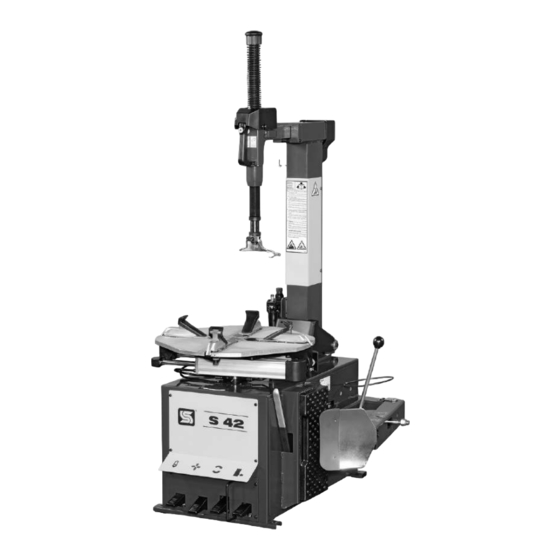
- Page 10 5- Pedale apertura/chiusura autocentrante 6- Griffa 7- Pedale ribaltamento palo 8- Palo ribaltabile 9- Maniglia comando bracci 10- Braccio verticale 11- Braccio orizzontale 12- Gruppo filtro lubrificatore 13- Appoggio in gomma 14- Paletta stallonatrice 15- Leva pneumatico 16- Torretta di montaggio/smontaggio S 42...
- Page 11 Pericolo schiacciamento delle gambe Pericolo di fuoriuscita di un forte getto d'aria. durante la stallonatura Pericolo schiacciamento mani tra cerchio Pericolo in fase di ribaltamento del palo e autocentrante durante la stallonatura S 42...
- Page 12 Per operare su ruote RUN FLAT, RIBASSATE o UHP è necessario disporre dell’accessorio (a richiesta) PT 250 e/o altri accessori dedicati. L’utilizzo degli accessori e la corretta procedura operativa vengono illustrati nei manuali allegati agli accessori stessi ed approvati dal WDK S 42...
- Page 13 (soprattutto nel caso si operi su ruote RUN FLAT, RIBASSATI, UHP). La procedura di stallonatura su ruote RUN FLAT, RIBASSATI, UHP richiede l’utilizzo del limitatore di corsa (vedi Fig. I/2), disponibile a richiesta . S 42...
- Page 14 Chiudere preventivamente le 4 griffe di bloccaggio (6, Fig. G) premendo a fondo il pedale (5, Fig. G). Appoggiare la ruota sull’autocentrante e premere a fondo il pedale (5, Fig. G): le 4 griffe si allargheranno bloccando il cerchione sugli appositi dentelli. S 42...
- Page 15 Prima di iniziare l’operazione di montaggio controllare che: - sia visivamente che al tatto il pneumatico non presenti difetti e la tela non risulti danneggiata. Se si riscontrano difetti NON montare il pneumatico - il cerchio non presenti ammaccature e/o deformazioni. S 42...
- Page 16 A montaggio ultimato premere il pedale (7, Fig. G) in modo da portare il palo (8, Fig. G) in posizione di fuori lavoro. 9) Premere il pedale (5, Fig. G) per liberare la ruota dall’autocentrante. N.B.: Entrambe le operazioni di smontaggio e montaggio vanno effettuate S 42...
- Page 17 RUOTE SPECIALI L’ S 42 dotato di appositi accessori, disponibili a richiesta, è in grado di operare su ruote speciali: PAX SYSTEM (con PT+KPX), SR Sup- port Ring (con PT+KSR), Run Flat, ribassate, UHP (con PT). Le procedure per operare correttamente su tali ruote sono descritte nel manuale istruzioni allegato all’accessorio specifico.
- Page 18 Con lo smontagomme viene fornito un apposito catalogo nel quale sono elencati gli accessori disponibili. Tutti gli accessori SICE vengono sempre forniti completi di istruzione per l'eventuale montaggio sullo smontagomme ed il corretto utilizzo. Non utilizzare MAI accessori non originali.
- Page 19 9) Passare la seconda cinghia fra i due scassi anteriori del piatto autocentrante come mostrato in Fig. O/1. 10) Con apposito anello di cinghia raccogliere, al di sopra della macchina, i capi delle cinghie di sostegno (vedi Fig. O/4). 11) Sollevare e trasportare con dispositivo idoneo adeguatamente dimensionato. S 42...
- Page 20 Con il vostro aiuto si può ridurre la quantità di risorse naturali impiegate per la realizzazione di apparecchiature elettriche ed elettroniche, minimizzare l’uso delle discariche per lo smaltimento dei prodotti e migliorare la qualità della vita evitando che sostanze potenzialmente pericolose vengano rilasciate nell’ambiente. S 42...
- Page 21 2) Ripristinare il passaggio dell'aria ed eventualmente sostituire il tubo se risul- tasse danneggiato. ATTENZIONE: Se le indicazioni sopra elencate non riportano lo smontagomme ad un corretto funzionamento o si riscontrano anomalie di altro tipo, NON utilizzare lo smontagomme e chiamare immediatamente il servizio tecnico di assistenza. S 42...
- Page 22 All manuals and user guides at all-guides.com ITALIANO • Manuale d’uso S 42...
- Page 23 10.5 Bead seating and inflating ......................37 11. ACCESSORIES ............................38 12. ROUTINE MAINTENANCE ........................38 13. FIRE-FIGHTING............................39 14. MOVING THE MACHINE .........................39 15. STORING ............................40 16. SCRAPPING A MACHINE ........................40 17. DATA ON SERIAL PLATE ........................41 18. TROUBLE SHOOTING ..........................41 S 42...
- Page 24 ENGLISH • Instructions manual 1. GENERAL INFORMATION The SICE S 42 tyre changer has been specially designed to demount and mount car and light industrial vehicle tyres with rims from 11” to 25” and a maximum diameter of 1100 mm (43”).
- Page 25 ENGLISH • Instructions manual 4. SAFETY DEVICES S 42 tyre changer is equipped with a pneumatic built-in safety valve. This valve prevents pressure coming from inflating gauges, or other inflating devices connected to the tyre changer, to exceed 3.5 bar.
- Page 26 12) Fit the tilting guard (15, Fig. B6) onto the post and fix it with the 4.8x16 self-tapping screw (16, Fig. B6) already fitted on the post. 13) Fix the air gun hook (17, Fig. B7) onto the post using the 2 M 6x10 Allen S 42...
- Page 27 FITTING THE BEAD BREAKER ARM 1) Fit the washer (21, Fig. D1) on the bead breaker arm support (see Fig. D1). S 42...
- Page 28 4) Press the spring down by hand to allow the knob to be put back onto the rod. 5) Keeping the knob lightly pressed down, fix it by fully tightening the screw removed earlier (see Fig. F2). 6) Release the hexagonal arm S 42...
- Page 29 Align the holes in the various parts to allow insertion of the NEW fixing pin, supplied in the kit (see Fig. K/8). 8) Secure the fixing pin with the 2 screws removed earlier. Re-connect the spring, using the plastic strip provided. S 42...
- Page 30 6- Wheel clamp 7- Tilting column pedal 8- Tilting column 9- Control arm handle 10- Hexagonal arm 11- Horizontal arm 12- Filter and lubricator 13- Rubber tyre rest 14- Bead breaker (loosener) blade 15- Tyre lever 16- Mounting/demounting head tool S 42...
- Page 31 Hand-crushing hazard during bead-breaking demounting operations. Hand-crushing hazard between rim and jaw during tyre locking. Danger: electric voltage Leg-crushing hazard during Air jet hazard bead-breaking Danger during tilting of the post. Hand-crushing hazard between rim and self-centering chuck during bead breaking. S 42...
- Page 32 The optional PT 250 accessory and/or other specific accessories are required to work on RUN FLAT, LOW PROFILE or UHP wheels. For use of the accessories and the correct operating procedure, refer to the manuals supplied with the accessories themselves, approved by WDK. S 42...
- Page 33 (especially when working on RUN FLAT, LOW PROFILE or UHP tyres). The optional stroke limiter (see Fig. I/2) is required for bead breaking on RUN FLAT, LOW PROFILE and UHP tyres. S 42...
- Page 34 Press the pedal (5, Fig. G) all the way down to close the 4 sliding clamps (6, Fig. G) completely. Put the wheel on the table top and depress pedal (5, Fig. G) all the way down. The 4 sliding clamps will open and clamp the wheel. S 42...
- Page 35 Before beginning mounting operations make sure that: - the tyre is not damage and the cord fabric is not damaged. If you note defects do not mount the tyre. - the rim is without dents and is not warped. S 42...
- Page 36 When the tyre is mounted, depress pedal (7, Fig. G) to move the column (8, Fig. G) to its non-work position. 9) Depress pedal (5, Fig. G) to release the wheel from the table top. S 42...
- Page 37 SPECIAL WHEELS When equipped with special optional accessories, the S 42 is able to work on special wheels: PAX SYSTEM (with PT+KPX), SR Sup- port Ring (with PT+KSR) and Run Flat, low profile and UHP (with PT).
- Page 38 A catalogue containing a list of the accessories available is supplied with the tyre changer. All SICE accessories come with a complete set of instructions for mounting on tyre changers and correct use. USE oNLY oRIGINAL SPARES. Using accessories that are not original can affect the safety of the tyre changer and immediately cause the SICE warranty to become invalid.
- Page 39 9) Pass the second strap between the two front slots on the turntable plate as shown in Fig. O/1. 10) Gather the ends of the slings in a suitable ring above the machine (see Fig. O/4). 11) Hoist and move the machine with a sufficiently strong lift truck. S 42...
- Page 40 With your help it is possible to reduce the amount of natural resources used to produce electrical and electronic equipments, to minimize the use of landfills for the disposal of the products and to improve the quality of life by preventing that potentially hazardous substances are released in the environment. S 42...
- Page 41 1) Check and correct the compressed air supply source. 2) Check and correct any hose defects. Replace hose if damaged. WARNING: If, inspite of the above mentioned indications the tyre changer doesn’t work properly, do not use it and call for technical assistance. S 42...
- Page 42 All manuals and user guides at all-guides.com ENGLISH • Instructions manual S 42...
- Page 43 10.5 Talonnage et gonflage ........................57 11. ACCESSOIRES ............................58 12. ENTRETIEN ORDINAIRE ........................58 13. NORMES CONTRE LES INCENDIES ......................59 14. MANUTENTION ............................59 15. REMISAGE ............................60 16. MISE A DECHARGE ..........................60 17. PLAQUE SIGNALETIQUE ........................61 18. INCONVENIENTES / CAUSES / REMEDES ....................61 S 42...
- Page 44 FRANÇAIS • Manuel d’instructions 1. GENERALITES Le démonte-pneus SICE S 42 est une machine réalisée pour démonter et monter des pneumatiques de voitures et de véhicules utilitaires avec des jantes de 11” à 25” et un diamètre max. de 1100 mm (43”).
- Page 45 4. DISPOSITIFS DE SECURITE Le démonte-pneus S 42 est équipé d’une vanne pneumatique de sécurité, placée à l’intérieur de l’appareil. Cette vanne empêche la pression débitée par les pistolets ou par autres dispositifs de gonflage branchés au démonte-pneus, de dépasser les 3,5 bars.
- Page 46 4,8x16 (16, Fig. B6) qui se trouve déjà sur le montant. 13) Fixer sur le montant le crochet pour pistolet (17, Fig. B7) en utilisant les 2 vis M 6x10 (18, Fig. B7) qui se trouvent déjà sur le montant. S 42...
- Page 47 1) Positionner la rondelle de calage (21, Fig. D1) sur le support du bras détalonneur (voir Fig. D1). 2) Appuyer sur la pédale du détalonneur (3, Fig. G) et la tenir pressée de façon à ce que la tige du vérin détalonneur (22, Fig. D2) rentre complètement. S 42...
- Page 48 4) Presser manuellement le ressort afin de pouvoir repositionner le pommeau sur la tige. 5) En maintenant le pommeau légèrement pressé, le fixer et serrer à fond la vis pré- cédemment enlevée (voir Fig. F2). 6) Débloquer le bras hexagonal. S 42...
- Page 49 Centrer les trous des différentes parties afin de pouvoir introduire le NOUVEAU pivot de blocage, fourni dans le kit (voir Fig. K/8). 8) Fixer le pivot de blocage avec les 2 vis précédemment enlevées. Accrocher de nouveau le ressort en utilisant la bande fournie. S 42...
- Page 50 9 - Poignée de commande des bras 10 - Bras coulissant vertical 11 - Bras horizontal 12 - Filtre et graisseur 13 - Butée en caoutchouc 14 - Palette détalonneur 15 - Levier pneumatique 16 - Tourelle de montage/démontage S 42...
- Page 51 Danger: présence de courant électrique. pneumatique. Danger d’écrasement des jambes pendant Danger: Jet d’air puissant le détalonnage. Danger d’écrasement des mains entre la Danger lors du basculement du montant jante et le mandrin pendant le détalonnage. S 42...
- Page 52 Pour intervenir sur des roues avec pneus RUN FLAT, SURBAISSÉS ou UHP, il faut avoir l’accessoire (fourni sur demande) PT 250 et/ou autres accessoires spécifiques. L’utilisation de ces accessoires et la procédure opérationnelle correcte sont illustrées dans les manuels annexés aux accessoires et approuvés par le WDK. S 42...
- Page 53 (RUN FLAT, SURBAISSÉS, UHP). La procédure de détalonnage sur des roues avec pneus RUN FLAT, SURBAISSÉS, UHP demande l’utilisation du limiteur de course (voir Fig. I/2), livré sur demande. S 42...
- Page 54 Fermer tout d’abord les 4 griffes de blocage (6 Fig. G) en appuyant à fond sur la pédale (5, Fig. G). Poser la roue sur l’autocentreur et enfoncer à fond la pédale (5, Fig. G): les 4 griffes s’ouvriront en bloquant la jante sur les dents prévues à cet effet. S 42...
- Page 55 Avant de commencer l’opération vérifier: - que le pneumatique, de visu et au toucher, n’a pas de défauts et la toile n’est pas endommagée. En présence de défauts NE PAS monter le pneumatique. - que la jante n’est pas cabossée ou déformée. S 42...
- Page 56 9) Appuyer sur la pédale (5, Fig. G) pour libérer la jante de l’autocentreur. NOTA - Les opérations de démontage et de montage doivent être effectuées en faisant tourner le plateau dans le sens des aiguilles d’une montre. Le sens de rotation inverse sert uniquement à rattraper une erreur éven- S 42...
- Page 57 ROUES SPECIALES Le S 42 peut être doté d’accessoires, fournis sur demande ; dans ce cas, il est en mesure d’opérer sur des roues spéciales : PAX SYSTEM (avec PT+KPX), SR Support Ring (avec PT+KSR), Run Flat, surbaissées, UHP (avec PT).
- Page 58 Un catalogue spécial est fourni avec le démonte-pneus dénommé “ACCESSoIRES DEMoNTE-PNEUS DE VoITURE” dans lequel sont répertoriés les acces- soires disponibles. Tous les accessoires SICE sont fournis avec les notices d’emploi de montage sur le démonte-pneus et sur leur utilisation N’utiliser jamais des accessoires qui ne sont pas d’origine.
- Page 59 9) Passer la deuxième courroie entre les deux rainures avant du plateau autocentreur comme illustré dans la Fig. O/1. 10) Avec un anneau de courroie, recueillir, au-dessus de l’appareil, les bouts des courroies de soutien (voir Fig. O/4). 11) Soulever et transporter avec un dispositif ayant les capacités appropriées. S 42...
- Page 60 Avec votre aide, il sera possible de réduire la quantité de ressources naturelles nécessaires à la fabrication des appareils électriques et électro- niques, de minimiser l’usage des déchetteries pour l’élimination des produits et d’améliorer la qualité de la vie en évitant que des substances potentiellement dangereuses ne souillent la nature. S 42...
- Page 61 2) Rétablir le passage de l’air et éventuellement remplacer le tuyau s’il est endommagé. ATTENTION: Si les indications ci-dessus ne permettent pas de remettre correctement en service le démonte-pneus ou s’il y a des anomalies de type différent, NE PAS utiliser le démont-pneus et appeler immédiatement le S.A.V. S 42...
- Page 62 All manuals and user guides at all-guides.com FRANÇAIS • Manuel d’instructions S 42...
- Page 63 10.4 Montage ............................75 10.5 Aufziehen und Aufpumpen ....................... 77 11. ZUBEHÖR ............................78 12. WARTUNG ............................78 13. BRANDBEKÄMPFUNGSVORSCHRIFTEN .....................79 14. BEWEGEN DER MASCHINE ........................79 15. LAGERHALTUNG ..........................80 16. VERSCHROTTEN ...........................80 17. DATEN DES TYPENSCHILDS ........................81 18. FEHLERSUCHE .............................81 S 42...
- Page 64 DEUTSCH • Betriebsanleitung 1. ALLGEMEINES Die Reifenmontiermaschine SICE S 42 ist eine Maschine zum Demontieren und Montieren von Pkw- und Llkw-Reifen mit Felgen von 11“ bis 25“ und max. Durchmesser von 1100 mm. (43“). Jede andere Verwendung ist als bestimmungswidrig und daher unzulässig zu betrachten.
- Page 65 DEUTSCH • Betriebsanleitung 4. SICHERHEITSVORRICHTUNGEN Die Reifenmontiermaschine S 42 ist mit einem pneumatischen Sicherheitsventil versehen, das innerhalb des Maschinenaufbaus installiert ist. Dieses Ventil verhindert, dass der von den Handfüllermessern oder anderen, an die Reifenmontiermaschine angeschlossenen Reifenfüllvorrichtungen abgegebene Druck den Wert von 3,5 bar überschreitet.
- Page 66 10) Das Gehäuse (13, Abb. B6) am Ständer einfügen und mit der Schlitzschraube M 6x12 (14, Abb. B6) befestigen. 11) Den Filter/Öler wieder einbauen. 12) Das Kippschutzgehäuse (15, Abb. B6) an den Ständer montieren und mit der selbstschneidenden Schraube 4,8x16 (16, Abb. B6) befestigen, die sich bereits am Ständer befindet. S 42...
- Page 67 1) Die Ausgleichsscheibe (21, Abb. D1) an die Halterung des Abdrückerarms (siehe Abb. D1) positionieren. 2) Das Schaltpedal der Abdrückeinrichtung (3, Abb. G) drücken und gedrückt halten, sodass die Stange des Abdrückzylinders (22, Abb. D2) vollständig eingefahren wird. S 42...
- Page 68 4) Die Feder mit der Hand zusammendrücken, um die Kappe wieder auf die Stange positionieren zu können. 5) Die Kappe leicht gedrückt halten und feststellen, indem man die zuvor ausgedrehte Schraube wieder eindreht (siehe Abb. F2). 6) Die Sechskantstange entsperren. S 42...
- Page 69 - Zwischen Wulstabdrückarm und Wegbegrenzer Die Bohrungen der verschiedenen Teile zentrieren, sodass der mitgelieferte NEUE Sperrbolzen eingesetzt werden kann (siehe Abb. K/8). 8) Den Sperrbolzen mit den 2 zuvor entfernten Schrauben befestigen. Unter Verwendung des mitgelieferten Befestigungsbands die Feder wieder einhaken. S 42...
- Page 70 7 - Pedal Mastumklappung 8 - Senkrechter Ständer 9 - Armsteuerungsgriff 10 - Senkrecht gleitender Träger des Montierkopfs 11 - Waagrechter Arm 12 - Filter und Öler 13 - Reifenanschlag aus Gummi 14 - Abdrückschaufel 15 - Reifenhebeeisen 16 - Montier-/Demontierkopf S 42...
- Page 71 Beim Radaufspannen besteht für die Hand Quetschgefahr zwischen Felge und Vorsicht: Spannungsführend. Spannklauen. Beim Abdrücken besteht für die Beine Vorsicht: Austritt kräftiger Druckluft. Quetschgefahr. Beim Abdrücken bersteht für die Hände Vorsicht beim Kippen des Ständers Quetschgefahr zwischen Felge und Spanntisch. S 42...
- Page 72 Für die Arbeit an RUNFLAT-, NIEDERQUERSCHNITTS- oder UHP-Rädern ist das Zubehör PT 250 (auf Anfrage lieferbar) und/oder anderes geeignetes Zubehör erforderlich. Die Anwendung des Zubehörs und die korrekte Arbeits-Vorge hensweise sind in den beiliegenden, von WDK genehmigten Zubehör-Handbüchern beschrieben. S 42...
- Page 73 Vor Beginn des Abdrückvorgangs muss zunächst festgestellt werden, um welchen Reifentyp es sich handelt (insbesondere im Fall von RUNFLAT-, NIEDERQUERSCHNITTS- oder UHP-Rädern). Für das Wulstabdrücken an RUNFLAT-, NIEDERQUERSCHNITTS- oder UHP-Rädern ist die Verwendung des Wegbegrenzers (siehe Abb. I/2) erforderlich (auf Anfrage lieferbar). S 42...
- Page 74 Vorher die 4 Spannklauen (6, Abb. G) schließen, indem man das Pedal (5, Abb. G) ganz durchdrückt. Das Rad auf den Spanntisch auflegen und das Pedal (5, Abb. G) durchtreten. Die 4 Spannklauen öffnen sich dabei und klemmen die Felge dabei fest. S 42...
- Page 75 Bevor man mit der Montage beginnt, ist folgendes zu prüfen: - Den Reifen betrachten und abtasten, um festzustellen, ob er Schäden aufweist oder die Karkasse beschädigt ist. Wenn Fehler ge- funden werden, den Reifen NICHT montieren. - Die Felge darf keine Verbeulungen und/oder Verformungen aufweisen. S 42...
- Page 76 8) Den unter Punkt 5 beschriebene Vorgang ist auf dem oberen Reifenwulst zu wiederholen. Nach beendeter Montage das Pedal (7, Abb. G) drücken, um den Mast (8, Abb. G) in die Position “außer Betrieb” zu bringen. 9) Das Pedal (5, Abb. G) drücken, um das Rad vom Spanntisch zu befreien. S 42...
- Page 77 Uhrzeigersinn wird nur gebraucht, um etwaige Bedienungsfehler auszubessern. SPEZIALRÄDER Wird S 42 mit entsprechenden, auf Anfrage verfügbaren Zubehörteilen ausgestattet, können mit diesem Modell auch Spezialräder montiert und demontiert werden: PAX SYSTEM (mit PT+KPX), SR Support Ring (mit PT+KSR), Runflat, Niederquerschnittsräder, UHP (mit PT).
- Page 78 Zum Lieferumfang der Reifenmontiermaschine gehört ein Katalog, Darin sind die lieferbaren Zubehörteile aufgeführt. Alle SICE-Zubehörteile werden immer mit der dazugehörigen Anleitung für die etwaige Montage auf der Reifenmontiermaschine und die korrekte Benutzung ausgeliefert. Benutzen Sie stets originalzubehörteile. Die Benutzung von Zubehör, das kein originalteil ist, kann die Sicherheit des Reifenmontiergeräts in Frage stellen und führt auch zum sofortigen Verfall der Garantie von SICE.
- Page 79 9) Den zweiten Gurt um die beiden vorderen Spalten in der Spannscheibe he- rumführen, wie in Abb. O/1 zu sehen ist. 10) Die Enden der Hebegurte am vorgesehenen Gurtring oberhalb der Maschine einfügen (vgl. Abb. O/4). 11) Die Maschine dann mit einem ausreichend tragfähigem Mittel heben und transportieren. S 42...
- Page 80 Mit Ihrer Hilfe lässt sich die Menge der natürlichen Ressourcen, die für die Realisierung von elektrischen und elektronischen Geräten benötigt werden, reduzieren, die Kosten für die Entsorgung der Produkte minimieren und die Lebensqualität erhöhen, da verhindert wird, dass giftige Substanzen in die Umwelt gebracht werden. S 42...
- Page 81 2) Für Durchgängigkeit des Schlauches sorgen. Schlauch ersetzen, falls er beschädigt ist. ACHTUNG: Wenn es ihnen trotz der obigen Angaben nicht gelingt, die Reifenmontiermaschine korrekt zum Laufen zu bringen oder wenn Störungen irgendwelcher Art vorliegen, verwenden Sie die Maschine NICHT, sondern verständigen umgehend den technishen Kundendienst. S 42...
- Page 82 All manuals and user guides at all-guides.com DEUTSCH • Betriebsanleitung S 42...
- Page 83 10.5 Talonado y inflado .......................... 97 11. ACCESORIOS ............................98 12. MANTENIMIENTO ORDINARIO ........................98 13. NORMAS ANTINCENDIO ........................99 14. TRASLADO DE LA MAQUINA ........................99 15. ALMACENADO ...........................100 16. DESGUAGE ............................100 17. DATOS DE MATRICULA ........................101 18. PROBLEMAS / CAUSAS / REMEDIOS ......................101 S 42...
- Page 84 ESPANOL • Manual de instrucciones 1. GENERALIDADES La desmontadora SICE S 42 es una máquina realizada para desmontar y montar neumáticos de coches y vehículos industriales ligeros con llantas de 11” a 25” y diámetro máx. 1100 mm. (43”) otros usos se consideran impropios y, por lo tanto, irracionales y no permitidos.
- Page 85 4. DISPOSITIVOS DE SECURIDAD La desmontadora de neumáticos S 42 está equipada con una válvula neumática de seguridad, situada en el interior del equipo. Esta válvula impide que la presión sumistrada por las pistolas o por otros dispositivos de inflado conectados a la desmontadora no supere los 3,5 bar.
- Page 86 12) Montar en la columna el cárter de protección vuelco (15, Fig. B6) y fijarlo con el tornillo autorroscante 4,8 x 16 (16, Fig. B6) que ya está colocado en la columna. 13) Fijar en la columna el gancho para pistola (17, Fig. B7) utilizando los dos tornillos S 42...
- Page 87 1) Posicionar la arandela de nivelación (21, Fig. D1) en el soporte del brazo destalonador (véase Fig. D1). 2) Presionar y mantener presionado el pedal destalonador (3, Fig. G) de manera que el asta del cilindro destalonador (22, Fig. D2) retorne por completo. S 42...
- Page 88 3) Introducir el resorte en la varilla hexagonal. 4) Presionar manualmente el resorte hasta obtener el reposicionamiento del pomo en la varilla. 5) Manteniendo el pomo ligeramente presionado, fijarlo apretando a fondo el tornillo precedentemente removido (véase Fig. F2). 6) Desbloquear el brazo hexagonal. S 42...
- Page 89 7) Hacer coincidir los agujeros de las diferentes piezas a fin de poder introducir el NUEVO perno de bloqueo suministrado incluido en el kit (véase Fig. K/8). 8) Fijar el perno de bloqueo con los dos tornillos anteriormente extraídos. Enganchar nuevamente el resorte utilizando la abrazadera suministrada adjunta. S 42...
- Page 90 5- Pedal para el cierre y apertura de las garras 6- Garra 7- Pedal vuelco columna 8- Columna vertical 9- Manija mando brazos 10- Brazo vertical 11- Brazo horizontal 12- Filtro/lubricador 13- Apoyo de goma 14- Pala destalonadora 15- Palanca neumático 16- Torre de montaje/desmontaje S 42...
- Page 91 Peligro de aplastamiento de los pies Peligro de salida de un fuerte golpe de aire. durante la fase de destalonado. Peligro de aplastamiento de las manos Peligro durante la fase de vuelco de la columna. entre lanta y autocentrante durante el destalonado. S 42...
- Page 92 Para operar con ruedas RUN FLAT, REBAJADAS o UHP es necesario disponer del accesorio (bajo pedido) PT 250 y/u otros accesorios dedicados. El uso de los accesorios y el correcto procedimiento operativo son ilustrados en los manuales adjuntos a los accesorios mismos y aprobados por WDK. S 42...
- Page 93 (sobre todo en caso de operar con ruedas RUN FLAT, REBAJADAS o UHP). El procedimiento de destalonadura en ruedas RUN FLAT, REBAJADAS y UHP requiere el uso del limitador de carrera (véase Fig. I/2), disponible bajo pedido. S 42...
- Page 94 Cerrar preventivamente las cuatro garras de bloqueo (6, fig. G) pulsando a fondo el pedal (5, fig. G). Apoyar la rueda sobre el autocentrante y pulsar a fondo el pedal (5, fig. G). Las 4 garras se abrirán bloqueando la llanta sobre sus dientes. S 42...
- Page 95 Antes de comenzar la operación de montaje controlar que: - Tanto visualmente como al tacto, el neumático no presente defectos y la lona no esté dañada. Si se encuentra algún defecto NO montar el neumático. - La llanta no presenta abolladuras o deformaciones. S 42...
- Page 96 Al finalizar el montaje accionar el pedal (7, fig. G) de forma que la columna (8, Fig. G) se desplace en posición de descanso. 9) Pulsar el pedal (5, fig. G) para liberar la rueda del autocentrante. NOTA: Ambas operaciones de desmontaje y montaje se efectúan girando el S 42...
- Page 97 RUEDAS ESPECIALES El S 42 equipado con accesorios específicos, disponibles bajo pedido, está en condiciones de operar en ruedas especiales: PAX SYSTEM (con PT+KPX), SR Support Ring (con PT+KSR), Run Flat, rebajadas y UHP (con PT). Los procedimientos para operar correctamente en dichas ruedas son ilustrados en el manual de instrucciones que acompaña al accesorio específico.
- Page 98 Los accesorios SICE se suministran con las intrucciones para un eventual montaje en la desmontadora y su uso correcto. No utilizar NUNCA accesorios no originales. La utilización de accesorios no originales puede perjudicar la seguridad de la desmontadora y provocar la inmediata anulación de la garantía SICE. 12. MANTENIMIENTO ORDINARIO ATENCION! Antes de cualquier operación de mantenimiento es necesario desconectar la desmontadora de las fuentes de...
- Page 99 9) Pasar la segunda cinta entre las dos guías delanteras como muestra la fig. O/1. 10) Mediante el respectivo anillo de correa, recoger por encima de la máquina los extremos de las correas de soporte (ver fig. O/4). 11) Levantar y transportar con el dispositivo idóneo adecuadamente dimensionado. S 42...
- Page 100 Con vuestra ayuda se puede reducir la cantidad de recursos naturales empleados en la fabricación de equipos eléctricos y electrónicos, mini- mizar el empleo de los vertederos para la eliminación de los productos y mejorar la calidad de la vida, evitando que sustancias potencialmente peligrosas sean vertidas en el entorno. S 42...
- Page 101 2) Verificar el recorrido de la tubería de aire y eventualmente sustituirlo si está dañado. ATENCION: Si las indicaciones arriba mostradas no reportan la desmontadora a un correcto funcionamiento o si se encuentran anomalias de otro tipo, NO utilizar la desmontadora y llamar al servicio de asistencia técnica. S 42...
- Page 102 All manuals and user guides at all-guides.com ESPANOL • Manual de instrucciones DICHIARAZIONE CE DI CONFORMITà Noi SICE SPA, Via Modena 34, 42015 Correggio (RE), ITALIA, dichiariamo che il prodotto Smontagomme S 42 al quale questa dichiarazione si riferisce e di cui abbiamo costituito e detenia- mo il relativo fascicolo tecnico è...
- Page 103 ESPANOL • Manual de instrucciones EC DECLARATION OF CONFORMITY We, SICE SPA, Via Modena 34 - 42015 CoRREGGIo (RE), ITALY, do hereby declare, that the product S 42 Tyre Changer to which this statement refers, manufactured by us and for which we hold the relative technical dossier, is com-...
- Page 104 Die vorliegende Erklärung entspricht in Form und Inhalt den Vorgaben der Norm EN 45014. DECLARACIÓN EC DE CONFORMIDAD La empresa abajo firmante, SICE SPA, Via Modena 34 - 42015 CORREGGIO (PU), ITALY, declara que el producto: Desmontadora de neumaticos S 42 al cual se refiere la presente declaración y del que hemos redactado y poseemos el correspondiente expediente...
- Page 105 All manuals and user guides at all-guides.com ESPANOL • Manual de instrucciones S 42...
- Page 106 SICE reserves the right to modify its machine at any time without prior notice. SICE declines any and all liability for injury to persons or damage to things caused by use of the machine other than that speci- fied or failure to observe the instructions detailed in this manual.