
Manuels Connexes pour Parker LX


Sommaire des Matières pour Parker LX
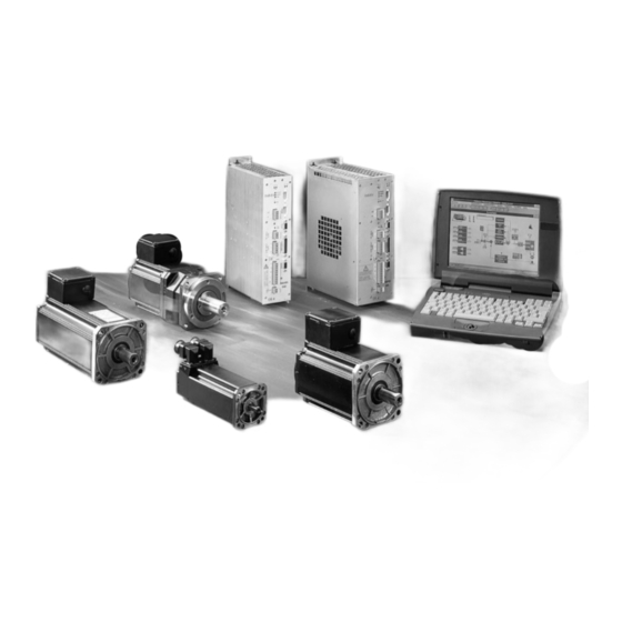
- Page 1 LX – LS – LD - LV MISE EN SERVICE ET UTILISATION COMMISSIONING AND USE AUFSTELLUNG UND BETRIEB PVD 3407 – 12/2013...
- Page 2 Conformité aux directives « C E » Les servomoteurs LX-LS-LD-LV répondent à la directive no 73/23/CEE du 19 février 1973 (modifiée par la directive no 93/68/CEE du 22 juillet 1993) et sont conformes aux normes EN 60034-1 et IEC 34-1/1994.
-
Page 3: Table Des Matières
TABLE DES MATIERES / CONTENTS / INHALTSVERZEICHNIS MISE EN SERVICE ET UTILISATION Consignes de sécurité Généralités Prescriptios de montage et d'utilisation Installation Raccordement électrique Aide au diagnostic COMMISSIONING AND USE Safety General Instructions for commissioning and use Installation Electrical connection Troubleshooting AUFSTELLUNG UND BETRIEB Risiken... -
Page 4: Mise En Service Et Utilisation
1. MISE EN SERVICE ET UTILISATION 1.1 Consignes de sécurité Les servoentraînements comportent deux types principaux de dangers : - Danger électrique Les servoamplificateurs peuvent comporter des pièces non isolées sous tension alternative ou continue. Avant l’installation de l’appareil, il est recommandé... -
Page 5: Généralités
1.2 Généralités 1.2.1 Description Les servomoteurs série LX, LS, LD et LV sont des servomoteurs brushless à aimants permanents, adaptés à la régulation de vitesse et aux asservissements de position. Ils sont optimisés pour fournir un couple élevé et des accélérations importantes grâce à la faible inertie de leur rotor. Les applications sont multiples et comprennent la robotique, les machines spéciales, la manutention, etc. -
Page 6: Prescriptios De Montage Et D'utilisation
1.3 Prescriptios montage d'utilisation 1.3.1 Réception du matériel Tous les servomoteurs font l’objet d’un contrôle rigoureux en fabrication, avant l’envoi. Vérifier l’état du servomoteur en enlevant soigneusement celui-ci de son emballage ; Vérifier également que les données de la plaque signalétique sont en conformité avec celles de l’accusé... - Page 7 1.4.2 Montage mécanique La durée de vie des roulements du servomoteur dépend pour une bonne part du soin apporté à cette opération. Dans le cas de servomoteur dont l’arbre comporte une clavette, s’assurer que les organes d’accouplement ont bien été équilibrés sans clavette, le servomoteur ayant été équilibré...
-
Page 8: Raccordement Électrique
1.5 Raccordement électrique Avant tout raccordement, vérifier que l’armoire électrique est hors tension. Ce branchement doit être conforme au manuel de mise en service du servoamplificateur, et les câbles choisis dans la gamme que nous proposons (ou de caractéristiques équivalentes). Choisir des câbles de section suffisante pour éviter des chutes de tension. - Page 9 1.5.3 Raccordement de la ventilation Certains servomoteurs peuvent être livrés en version ventilée. Caractéristiques du moto-ventilateur : Tension d’alimentation : 400V triphasé 50/60 HZ (version standard). Puissance consommée : 45 W Raccordement par connecteur (fiche 220056P0200 coudée). Vérifier le sens de rotation du ventilateur et la présence effective d’un flux d’air.
-
Page 10: Aide Au Diagnostic
1.5.6 Câble et connecteur de raccordement resolver Câble resolver Le câble resolver doit être séparé du câble de puissance. Les câbles équipés de connecteurs peuvent être livrés par nos soins : nous consulter. Le câble est constitué de 3 paires torsadées et blindées par paires. Le blindage des paires doit être relié... - Page 11 – Vérifiez qu’il n’y a pas de blocage mécanique ou de grippage. Vous constatez que le – Vérifiez l’alimentation du frein. moteur ne tourne pas à la main : – Vous avez des Contrôlez les fusibles, la tension aux bornes (la charge peut être excessive ou difficultés à...
-
Page 12: Commissioning And Use
2. COMMISSIONING AND USE 2.1 Safety Servodrives present two main types of hazard : - Electrical hazard Servoamplifiers may contain non-insulated live AC or DC components. Users are advised to guard against access to live parts before installing the equipment. Even after the electrical panel is de-energized, voltages may be present for more than a minute, until the power capacitors have had time to discharge. -
Page 13: General
2.2 General 2.2.1 Description LX, LS, LD and LV series servomotors are brushless servomotors with permanent magnets, designed for speed and position control. These servomotors are optimized to give high torque and fast acceleration thanks to the low rotor inertia. -
Page 14: Instructions For Commissioning And Use
2.3 Instructions for commissioning and 2.3.1 Equipment delivery All servomotors undergo a thorough quality control procedure before dispatch :. Check the condition of the servomotor by carefully removing it from its packaging ; Check that the information on the identification plate corresponds to your order. Check also the accessories included in the box. - Page 15 2.4.2 Mechanical installation The service life of the servomotor bearings depends largely on the care exercised during this operation. Ensure that the coupling devices are well balanced without a key, as the servomotor has been balanced with the whole key (in the case of servomotors with a key).
-
Page 16: Electrical Connection
2.5 Electrical connection Before making any connections, make sure power to the electrical cabinet is off. This connection must comply with the servoamplifier installation manual, and the cables selected from the range we offer (or equivalent characteristics). Choose cables with a cross-section large enough to prevent voltage drops. If the cable is more than 25 m long, a filter may be required at the servoamplifier output : ask us for details. - Page 17 2.5.3 Ventilation connection Fan cooled versions are available for some servomotors. The blower data are : Supply voltage : 400 V three- phase - 50/60 HZ (standard version) Power consumed : 45 W Connector fitting (L-type plug 220056P0200).
-
Page 18: Troubleshooting
2.5.6 Cable and connector for resolver connexion resolver Cable The resolver cable must be separated from the power cable. Cables fitted with connectors may be provided by us : ask for details. The cable is made up of 3 twisted pair shielded by pairs. The pair shielding must be connected to the servoamplifier reference potential. - Page 19 You note that the motor Check the electricity supply to the brake. does not turn by hand Check there is no mechanical blockage or seizing. You have difficulty Check the fuses, voltage at the terminals (the load may be too high or the starting the motor or bearings may be seized) and the load current.
-
Page 20: Aufstellung Und Betrieb
3. AUFSTELLUNG UND BETRIEB 3.1 Risiken Bei Servoantrieben bestehen hauptsächlich zwei Risiken: - Gefährdung durch Strom Servoverstärker können nichtisolierte Teile enthalten, an denen Gleich- oder Wechselspannung anliegt. Vor der Installation des Gerätes empfehlen wir, leitende Teile vor unbeabsichtigter Berührung zu schützen. Selbst wenn der Schaltschrank bereits seit mehr als einer Minute ausgeschaltet ist, kann noch Spannung vorhanden sein, da diese Zeit zur Entladung der Leistungskondensatoren nötig ist. -
Page 21: Allgemeines
3.2 Allgemeines 3.2.1 Beschreibung Bei den Servomotoren der Reihen LX, LS, LD und LV handelt es sich um permanenterregte bürstenlose Servomotoren, die den Erfordernissen von Drehzahlregelung und Positionieraufgaben entsprechen. Dank der geringen Massenträgheit ihres Rotors liefern sie ein großes Drehmoment und ermöglichen schnelle Beschleunigungen. -
Page 22: Montage
3.3 Montage 3.3.1 Empfang des Materials Alle Servomotoren werden vor dem Versand sorgfältig überprüft. Prüfen Sie den einwandfreien Zustand des Servomotors, indem Sie ihn vorsichtig von seiner Verpackung befreien. Die Servomotoren dürfen nicht mit Hilfe der Kabel bewegt werden. ... - Page 23 3.4.2 Mechanische Montage Die Lebensdauer der Wälzlager hängt wesentlich von der Sorgfalt ab, mit der diese Montage durchgeführt wird. Überprüfen Sie, bei einem Servomotor, dessen Welle eine Paßfeder enthält, daß die Ankupplungselemente ohne paßfeder gut ausgewuchtet sind, da der Servomotor mit Paßfeder ausgewuchtet wurde.
-
Page 24: Elektrischer Anschluss
3.5 Elektrischer Anschluss Vor jedem Anschluß ist sicherzustellen, daß der Schaltschrank spannungslos ist. Der Anschluß muß gemäß den Angaben in der Inbetribnahmeanleitung des Servoversträrkers erfolgen, und die dazu vorgesehenen Kabel sollten der von uns verwendeten Qualität entsprechen (oder zumindest sehr ähnlich beschaffen sein). Der Kabelquerschnitt muß... - Page 25 3.5.3 Anschluß des Lüfters Bestimmte Servomotoren werden mit Fremdbelüftung geliefert. Der Lüfter hat folgende Kenndaten : Versorgungsspannung : 400 V Drehstrom 50/60HZ (Standardausführung). Leistungsaufnahme : 45 W Anschluß Über Winkelstecker (220056P0200). Überprüfen Sie die Drehrichtung des Lüfters und das effektive Vorliegen eines Luftstroms. 3.5.4 Anschluß...
-
Page 26: Fehlersuche
3.5.6 Kabel und Stecker für den Resolveranschluß Wir raten Ihnen, das empfohlene Kabel zu verwenden und es getrennt von dem Leistunganschluß zu verlegen. Auf Wunsch liefern wir gerne die mit Steckern versehenen Kabel. Das Kabel besteht aus 3 Aderpaaren, die jeweils für sich verdrillt und abgeschirmt sind. - Page 27 Der Motor läßt sich nicht von Stromversorgung der Bremse überprüfen, die Lager können festgefressen sein. Hand drehen Motor Prüfen Sie die Sicherungen, die Klemmenspannung (zu große Last oder Schwierigkeiten anzulaufen festgefressene Lager) sowie den Strom. oder läßt sich nicht drehen Überprüfen Sie die Spannungsversorgung der bremse (+ 24 V, ±10%) und ihre Polarität.
-
Page 28: Annexe - Appendix - Anhang
4. ANNEXE – APPENDIX - ANHANG 1 fiches connecteur et câbles de puissance / cables and connectors / kabel und-stecker Fiche standard Fiche spécifique Références Type de câble Intensité Diamètre Rayon de métallique métallique du câble de permanente du cable courbure Standard metallic Specific metallic... -
Page 29: Annexe - Appendix - Anhang
5. ANNEXE – APPENDIX – ANHANG 2 fiches connecteur de raccordement resolver /connector for resolver / stecker für resolver fiches connecteur standard métallique Borne Fonction Couleur câble Metal Standard connectors Function Cable colour Metallstandardstecker Belegung Funktion Kabelfarbe Cosinus Rouge / Red / Rot Cosinus Noir / Black / Schwarz ... -
Page 30: Annexe - Appendix - Anhang
• standard LX 2/LX 3 : with connector • standard LX 2/LX 3 : mit Stecker • LX 4, LX 6, LS, LD, LV : par boîte à • LX 4, LX 6, LS, LD, LV : with • LX 4, LX 6, LS, LD, LV : mit bornes terminal box.