Table des Matières
Publicité
Les langues disponibles
Les langues disponibles
Liens rapides
Betriebsanleitung | Operating instructions | Mode d'emploi | Istruzioni per l'uso |
Instrucciones de servicio | Bruksanvisning
Buskoppler CMS, B-Design
Bus coupler for CMS, B-Design
Coupleur de bus pour CMS, design B
Accoppiatore bus per CMS, design B
Acoplador de bus para CMS, diseña B
Fältbussnod för CMS, B-Design
PROFIBUS DP
R499050016/04.2015, Replaces: 05.2014, DE/EN/FR/IT/ES/SV
Publicité
Chapitres
Table des Matières

Manuels Connexes pour Aventics PROFIBUS DP


Sommaire des Matières pour Aventics PROFIBUS DP
- Page 1 Instrucciones de servicio | Bruksanvisning Buskoppler CMS, B-Design Bus coupler for CMS, B-Design Coupleur de bus pour CMS, design B Accoppiatore bus per CMS, design B Acoplador de bus para CMS, diseña B Fältbussnod för CMS, B-Design PROFIBUS DP R499050016/04.2015, Replaces: 05.2014, DE/EN/FR/IT/ES/SV...
-
Page 3: Table Des Matières
AVENTICS | PROFIBUS DP | R499050016–BDL–001–AE Zu dieser Anleitung ......................5 Gültigkeit der Dokumentation ......................5 Erforderliche und ergänzende Dokumentationen................5 Darstellung von Informationen ......................6 1.3.1 Sicherheitshinweise ..........................6 1.3.2 Symbole ..............................7 Verwendete Abkürzungen........................8 Zu Ihrer Sicherheit ......................8 Zu diesem Kapitel ..........................8 Bestimmungsgemäßer Gebrauch.....................8... - Page 4 AVENTICS | PROFIBUS DP | R499050016–BDL–001–AE Inbetriebnahme und Bedienung ..................31 Voreinstellungen vornehmen......................31 7.1.1 Baudrate einstellen .......................... 31 7.1.2 Dem Buskoppler eine Adresse zuweisen .................. 32 7.1.3 Diagnosemeldungen einstellen ....................33 7.1.4 Ventilversorgung zuordnen ......................34 7.1.5 Busabschluss einstellen ......................... 41 Buskoppler konfigurieren am Beispiel WinDP................
-
Page 5: Zu Dieser Anleitung
AVENTICS | PROFIBUS DP | R499050016–BDL–001–AE Zu dieser Anleitung Zu dieser Anleitung Gültigkeit der Dokumentation Diese Anleitung enthält wichtige Informationen, um den Buskoppler sicher und sachgerecht zu montieren, zu bedienen, zu warten und einfache Störungen selbst zu beseitigen. Lesen Sie diese Anleitung vollständig und insbesondere das Kapitel 2 „Zu Ihrer Sicherheit“... -
Page 6: Darstellung Von Informationen
AVENTICS | PROFIBUS DP | R499050016–BDL–001–AE Zu dieser Anleitung Darstellung von Informationen Damit Sie mit dieser Dokumentation schnell und sicher mit Ihrem Produkt arbeiten können, werden einheitliche Sicherheitshinweise, Symbole, Begriffe und Abkürzungen verwendet. Zum besseren Verständnis sind diese in den folgenden Abschnitten erklärt. -
Page 7: Symbole
AVENTICS | PROFIBUS DP | R499050016–BDL–001–AE Zu dieser Anleitung Tabelle 2: Gefahrenklassen nach ANSI Z535.6-2006 Warnzeichen, Signalwort Bedeutung Kennzeichnet eine gefährliche Situation, in der Tod oder schwere GEFAHR Körperverletzung eintreten werden, wenn sie nicht vermieden wird Kennzeichnet eine gefährliche Situation, in der Tod oder schwere WARNUNG Körperverletzung eintreten können,... -
Page 8: Verwendete Abkürzungen
AVENTICS | PROFIBUS DP | R499050016–BDL–001–AE Zu Ihrer Sicherheit Verwendete Abkürzungen Abkürzung Bedeutung Ventilsystem Gerätestammdaten EP-Endplatte Endplatte mit elektrischen und pneumatischen Anschlüssen P-Endplatte Endplatte mit pneumatischen Anschlüssen E-Endplatte Endplatte mit elektrischen Anschlüssen Zu Ihrer Sicherheit Zu diesem Kapitel Der Produkt wurde entsprechend dem heutigen Stand der Technik hergestellt. -
Page 9: Nicht Bestimmungsgemäßer Gebrauch
Anwendungen ein, wenn diese Verwendung ausdrücklich in der Dokumentation des Produkts spezifiziert und erlaubt ist. Für Schäden bei nicht bestimmungsgemäßer Verwendung übernimmt die AVENTICS GmbH keine Haftung. Die Risiken bei nicht bestimmungsgemäßer Verwendung liegen allein beim Benutzer. Als nicht bestimmungsgemäße Verwendung gilt, wenn Sie den Buskoppler außerhalb der Anwendungsgebiete verwenden, die in dieser... -
Page 10: Qualifikation Des Personals
AVENTICS | PROFIBUS DP | R499050016–BDL–001–AE Zu Ihrer Sicherheit Qualifikation des Personals Die Montage, Demontage, Inbetriebnahme und Bedienung erfordert grundlegende elektrische und pneumatische Kenntnisse sowie Kenntnisse der zugehörigen Fachbegriffe. Die Montage, Demontage, Inbetriebnahme und Bedienung darf daher nur von einer Elektro- oder Pneumatikfachkraft oder von einer unterwiesenen Person unter der Leitung und Aufsicht einer Fachkraft erfolgen. -
Page 11: Produkt- Und Technologieabhängige Sicherheitshinweise
Produkts spezifiziert und erlaubt ist. Sie dürfen das Produkt erst dann in Betrieb nehmen, wenn festgestellt wurde, dass das Endprodukt (beispielsweise eine Maschine oder Anlage), in das die AVENTICS-Produkte eingebaut sind, den länderspezifischen Bestimmungen, Sicherheitsvorschriften und Normen der Anwendung entspricht. -
Page 12: Einsatzbereiche
AVENTICS | PROFIBUS DP | R499050016–BDL–001–AE Einsatzbereiche Erden Sie die Module und das Ventilsystem. Beachten Sie die folgenden Normen bei der Installation des Systems: – DIN EN 50178, Klassifikation VDE 0160 – VDE 0100 Bei der Inbetriebnahme Die Installation darf nur in spannungsfreiem und drucklosem Zustand und nur durch geschultes Fachpersonal erfolgen. -
Page 13: Lieferumfang
AVENTICS | PROFIBUS DP | R499050016–BDL–001–AE Lieferumfang Ausgangssignale über den Busanschluss des Ventilsystems auszugeben. Der Buskoppler ist ausschließlich für den Betrieb als Slave an einem Bussystem PROFIBUS DP nach EN 50170 Teil 2 bestimmt. Lieferumfang Im Lieferumfang sind enthalten: 1 Ventilsystem gemäß Konfiguration und Bestellung... -
Page 14: Gesamtübersicht Ventilsystem Und Module
AVENTICS | PROFIBUS DP | R499050016–BDL–001–AE Gerätebeschreibung Gesamtübersicht Ventilsystem und Module Das Ventilsystem setzt sich, je nach Bestellumfang, aus den in Abbildung 1 dargestellten Komponenten zusammen: Abb. 1: Gesamtübersicht: Beispielkonfiguration Buskoppler mit I/O-Modulen und montiertem VS 1 E-Endplatte 5 EP-Endplatte für HF03 LG oder HF04 2 Output-Modul 6 Ventilträger... -
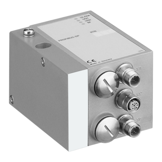
Page 15: Gerätekomponenten
AVENTICS | PROFIBUS DP | R499050016–BDL–001–AE Gerätebeschreibung Gerätekomponenten 5.2.1 Buskoppler Abb. 2: Übersicht über den Buskoppler LED-Anzeigen für Diagnosemeldungen BTN-Beschriftungsfeld X71 (BUS IN) Anschluss für den Buskoppler zur Ansteuerung der Ventile und der I/O-Module X72 (BUS OUT) Anschluss zur Ansteuerung der Ventile und... -
Page 16: Input-/Output-Module
AVENTICS | PROFIBUS DP | R499050016–BDL–001–AE Gerätebeschreibung Der Buskoppler ist ausschließlich für den Betrieb als Slave an einem Bussystem PROFIBUS DP-Bussystem nach EN 50170 Teil 2 bestimmt. Als Feldbuskabel wird ein verdrilltes, geschirmtes Adernpaar benutzt. Die Buslänge kann in Abhängigkeit von der Übertragungsgeschwindigkeit (ohne Repeater) bis zu 1,2 km... -
Page 17: Input-Module
AVENTICS | PROFIBUS DP | R499050016–BDL–001–AE Gerätebeschreibung werden – insgesamt jedoch maximal 6 Module. Die Reihenfolge ist hierbei beliebig. Achten Sie darauf, die Belastbarkeitsgrenzen einzuhalten! Der Buskoppler versorgt die Eingänge der Input-Module. Der maximale Summenstrom für alle Eingänge beträgt 0,7 A. -
Page 18: Output-Module
AVENTICS | PROFIBUS DP | R499050016–BDL–001–AE Gerätebeschreibung 5.2.4 Output-Module Die Output-Module zum Anschluss der Aktoren sind in zwei Ausführungen erhältlich: 8 x M8 (RMV04-8DO_M8) oder 4 x M12, doppelt belegt (RMV04-8DO_M12) Abb. 4: Output-Modul 8fach: RMV04-8DO_M8 (links) und RMV04-8DO_M12 (rechts) -
Page 19: Montage
AVENTICS | PROFIBUS DP | R499050016–BDL–001–AE Montage Montage Buskoppler am Ventilsystem montieren Sie erhalten Ihr individuell konfiguriertes Ventilsystem der Serie HF03 LG oder HF04 komplett verschraubt mit allen Komponenten: Ventilträger Buskoppler gegebenenfalls I/O-Module Die Montage des gesamten Ventilsystems ist in der beiliegenden Betriebsanleitung für das VS ausführlich... -
Page 20: Abmessungen
AVENTICS | PROFIBUS DP | R499050016–BDL–001–AE Montage 6.1.1 Abmessungen A + (60 x m) B + (60 x m) Abb. 5: Maßzeichnung Ventilsystem (Buskoppler und Ventile), Beispiel (m = Anzahl der Input-/Output-Module) Durch jedes Input-/Output-Modul wird das Ventilsystem um 60 mm verlängert (60 x m). Die E-Endplatte hat eine Anbautiefe... -
Page 21: Module Beschriften
AVENTICS | PROFIBUS DP | R499050016–BDL–001–AE Montage Module beschriften Buskoppler Beschriften Sie die für den Buskoppler vorgesehene/ verwendete Adresse am Buskoppler im Feld BTN. Input-/Output-Module Beschriften Sie die Anschlüsse direkt auf den Beschriftungsfeldern der Input-/Output-Module. Die Zuordnung der Beschriftungsfelder zu den Anschlüssen ist durch die Bezeichnung der Anschlüsse gegeben. -
Page 22: Allgemeine Hinweise Zum Anschluss Des Buskopplers
AVENTICS | PROFIBUS DP | R499050016–BDL–001–AE Montage ACHTUNG Falsche Verkabelung Eine falsche oder fehlerhafte Verkabelung führt zu Fehlfunktionen und zur Beschädigung des Bussystems. Halten Sie – sofern nicht anders erwähnt – die Aufbaurichtlinien PROFIBUS DP/FMS (PROFIBUS- Richtlinie, PNO-Best.-Nr. 2.111) ein. -
Page 23: Buskoppler Als Zwischenstation Anschließen
Die Zuordnung der grünen Ader des Buskabels zur Datenleitung A (RxD/TxD-N) und der roten Ader zur Datenleitung B (RxD/TxD-P) ist nicht genormt. AVENTICS empfiehlt die Zuordnung wie in der Tabelle angegeben. Bei Verwendung eines Kabels mit Beilauflitze kann diese zusätzlich an Pin 5 der Busstecker (X71, X72) angeschlossen werden. -
Page 24: Buskoppler Als Letzte Station Anschließen
AVENTICS | PROFIBUS DP | R499050016–BDL–001–AE Montage verwenden. So schützen Sie die Datenleitungen gegen Störungseinkopplungen. Stellen Sie sicher, dass das Steckergehäuse fest mit dem Buskopplergehäuse verbunden ist. 6.3.3 Buskoppler als letzte Station anschließen 1. Stellen Sie die korrekte Pin-Belegung (siehe Tabelle 4 auf Seite 23) Ihrer Steckerverbindungen her, wenn Sie eine unkonfektionierte Verkabelung verwenden. - Page 25 AVENTICS | PROFIBUS DP | R499050016–BDL–001–AE Montage Tabelle 5: Belegung des Gerätesteckers X10 (POWER), M12, A-codiert Belegung Spannungsversorgung Buskoppler-Logik und Sensorversorgung der digitalen Eingangsmodule erste Spannungsversorgung Ventile Masse für U und U zweite Spannungsversorgung Ventile und U sind galvanisch miteinander verbunden.
- Page 26 AVENTICS | PROFIBUS DP | R499050016–BDL–001–AE Montage VORSICHT Unsichere Netzteil-Trennung Die 24-V-Versorgung kann aus einem gemeinsamen Netzteil erfolgen. Eine unsichere Netzteil-Trennung kann zur Schädigung des Systems und zu Verletzungen durch Stromschlag führen. Verwenden Sie nur ein Netzteil mit einer sicheren...
-
Page 27: Input-/Output-Module 8Fach Anschließen
AVENTICS | PROFIBUS DP | R499050016–BDL–001–AE Montage 6.3.5 Input-/Output-Module 8fach anschließen VORSICHT Frei zugängliche stromführende Teile Gefahr von Stromschlag bei Berührung! Halten Sie beim Anschluss der Peripherie (E/A- Schnittstelle) die Anforderungen des Berührungsschutzes gemäß EN 50178, Klassifikation VDE 0160 ein. - Page 28 AVENTICS | PROFIBUS DP | R499050016–BDL–001–AE Montage Tabelle 8: Belegung der Eingänge beim Input-Modul 8fach, DI8_M12, Buchse M12x1, A-codiert Signal Belegung SENSOR– GND-Bezugspotenzial I0, I2, I4 oder I6 Sensorsignal nicht belegt Gehäuse liegt auf Shield-Potenzial Output-Modul 1. Verdrahten Sie die Ausgänge nach Tabelle 9 (DO8_M8) bzw.
-
Page 29: Lastversorgung Des Output-Moduls Anschließen
AVENTICS | PROFIBUS DP | R499050016–BDL–001–AE Montage Tabelle 10: Belegung der Ausgänge beim Output-Modul 8fach, DO8_M12, Buchse M12x1, A-codiert Signal Belegung nicht belegt Gehäuse liegt auf Shield-Potenzial ACHTUNG Zu hoher Summenstrom Jeder Ausgang ist für einen Dauerstrom von max. 0,5 A ausgelegt. - Page 30 Schrauben Sie hierzu die Schraube für den FE-Anschluss aus der EP-Endplatte des VS (1) heraus und in die E-Endplatte (2) ein. Stellen Sie dann dort die Verbindung mit der Funktionserde her. Abb. 7: FE-Anschluss am VS HF04 mit PROFIBUS DP an EP-Endplatte (1) oder an E-Endplatte (2)
-
Page 31: Inbetriebnahme Und Bedienung
AVENTICS | PROFIBUS DP | R499050016–BDL–001–AE Inbetriebnahme und Bedienung Erdung bei Bringen Sie die Erdung am FE-Anschluss der VS HF03 LG E-Endplatte (2) an. Inbetriebnahme und Bedienung Voreinstellungen vornehmen Folgende Voreinstellungen müssen Sie durchführen: Baudrate einstellen Dem Buskoppler eine Adresse zuweisen... -
Page 32: Dem Buskoppler Eine Adresse Zuweisen
AVENTICS | PROFIBUS DP | R499050016–BDL–001–AE Inbetriebnahme und Bedienung 7.1.2 Dem Buskoppler eine Adresse zuweisen Der Buskoppler wird werksseitig mit der Stationsadresse 0 ausgeliefert. Erkennt das ASIC im Buskoppler beim Einschalten den nicht zulässigen Wert 0, wird automatisch die Stationsadresse mit 126 belegt, bis der Anwender die Stationsadresse mittels S1 und S2 auf den gewünschten Wert... -
Page 33: Diagnosemeldungen Einstellen
AVENTICS | PROFIBUS DP | R499050016–BDL–001–AE Inbetriebnahme und Bedienung 7.1.3 Diagnosemeldungen einstellen Der Mode-Schalter S3 für die Einstellung der Diagnosemeldungen befindet sich unter der PG-Verschraubung A (siehe Abbildung 8 auf Seite 32). Bei der Auslieferung befinden sich alle Schalter in der OFF-Position. -
Page 34: Ventilversorgung Zuordnen
AVENTICS | PROFIBUS DP | R499050016–BDL–001–AE Inbetriebnahme und Bedienung 7.1.4 Ventilversorgung zuordnen Die Schalter S4, S5 und S6 für die Zuordnung der Ventilversorgung befinden sich unter der PG-Verschraubung B (siehe Abbildung 9). Jedem Schalter sind zugeordnet: 4 Anschlussplattenplätze für beidseitig betätigte Ventile (mit Spulen 12 und 14) oder 8 Anschlussplattenplätze für einseitig betätigte Ventile... - Page 35 AVENTICS | PROFIBUS DP | R499050016–BDL–001–AE Inbetriebnahme und Bedienung Bei Auslieferung befinden sich die Schalter S4...S6 in der Stellung U VORSICHT Spannung an Schaltern Schalter können beschädigt werden, wenn bei ihrer Bedienung eine Spannung anliegt. Betätigen Sie die Schalter nur in spannungslosem...
- Page 36 AVENTICS | PROFIBUS DP | R499050016–BDL–001–AE Inbetriebnahme und Bedienung Für die Zuordnung der Schalter S4, S5 und S6 und der Versorgung montierter Ventile finden Sie die Beispiele für 24 Ventilspulen in Tabelle 14 und Tabelle 15 auf den Seiten 37, 38 und für 32 Ventilspulen in den Tabelle 16 und Tabelle 17 auf...
- Page 37 AVENTICS | PROFIBUS DP | R499050016–BDL–001–AE Inbetriebnahme und Bedienung Tabelle 14: Beispiele für die Zuordnung von Schaltern und Ventilversorgung, 24 Ventilspulen Beispiel 1 Beispiel 2 Beispiel 3 Anschlussplatte für beidseitig betätigte Ventile Ventil- Spule Ventil- Ventil- Spule LED Spule LED...
- Page 38 AVENTICS | PROFIBUS DP | R499050016–BDL–001–AE Inbetriebnahme und Bedienung Tabelle 15: Beispiele für die Zuordnung von Schaltern und Ventilversorgung, 24 Ventilspulen Beispiel 4 Beispiel 5 Beispiel 6 Anschlussplatte für Anschlussplatte für ein- und beidseitig betätigte einseitig betätigte Ventile Ventile Ventilplatz...
- Page 39 AVENTICS | PROFIBUS DP | R499050016–BDL–001–AE Inbetriebnahme und Bedienung Tabelle 16: Beispiele für die Zuordnung von Schaltern und Ventilversorgung, 32 Ventilspulen Beispiel 1 Beispiel 2 Beispiel 3 Anschlussplatte für beidseitig betätigte Ventile Ventilplatz Spule LED Ventilplatz Spule LED Ventilplatz Spule LED A0.0...
- Page 40 AVENTICS | PROFIBUS DP | R499050016–BDL–001–AE Inbetriebnahme und Bedienung Tabelle 17: Beispiele für die Zuordnung von Schaltern und Ventilversorgung, 32 Ventilspulen Beispiel 4 Beispiel 5 Beispiel 6 Anschlussplatte für Anschlussplatte für ein- und beidseitig einseitig betätigte Ventile betätigte Ventile Ventilplatz...
-
Page 41: Busabschluss Einstellen
Ruhepegel auf der Übertragungsleitung des PROFIBUS DP sicherzustellen, muss die Übertragungsleitung an beiden Enden mit einem Busabschluss versehen werden. Beim Modul PROFIBUS DP ist der Busabschluss im Gerät integriert und kann über die Schalter S7 und S8 definiert werden. ON OFF S4 S5 S6 Abb. -
Page 42: Buskoppler Konfigurieren Am Beispiel Windp
AVENTICS | PROFIBUS DP | R499050016–BDL–001–AE Inbetriebnahme und Bedienung Buskoppler konfigurieren am Beispiel WinDP Die Beschreibung in diesem Kapitel bezieht sich auf die Software WinDP, Version 1.94 (AVENTICS Best.-Nr. 1070077945). WinDP enthält auch eine Online-Dokumentation, die Sie bei der Bedienung berücksichtigen müssen. -
Page 43: Gerätestammdaten Einspielen
AVENTICS | PROFIBUS DP | R499050016–BDL–001–AE Inbetriebnahme und Bedienung ACHTUNG Konfigurationsfehler Ein fehlerhaft konfigurierter Buskoppler kann zu Fehlfunktionen im System führen und eine Schädigung des Systems zur Folge haben. Die Konfiguration darf daher nur von einer Elektronik- Fachkraft durchgeführt werden! Konfigurieren Sie das Bussystem gemäß... -
Page 44: Voreinstellungen In Windp Vornehmen
AVENTICS | PROFIBUS DP | R499050016–BDL–001–AE Inbetriebnahme und Bedienung Die GSD-Datei kann im Internet unter der Adresse www.aventics.com heruntergeladen werden. Bei Inbetriebnahme eines Buskopplers für die Ansteuerung von 32 Ventilspulen (R412008079) müssen Sie eine GSD-Datei mit Versionsstand 1.3 verwenden. -
Page 45: Busteilnehmer Konfigurieren
Sie mit „OK“. Danach gelangen Sie in den Editor von WinDP. Hier konfigurieren Sie den PROFIBUS DP. Im Arbeitsbereich des Editors ist in der ersten Hierarchieebene bereits der von Ihnen angegebene Busmaster angelegt und die Busadresse 1 eingetragen: Abb. - Page 46 AVENTICS | PROFIBUS DP | R499050016–BDL–001–AE Inbetriebnahme und Bedienung Abb. 13: Dialogfenster WinDP-Editor, Bezeichnung der Fenster 1 Arbeitsbereich 2b Ventilsystem und Module 2 BTN-Fenster 3 E/A-Fenster 2a Bezeichnung des Buskopplers 2. Wählen Sie im BTN-Fenster den Buskoppler des Ventilsystems aus, um das Ventilsystem als Slave im PROFIBUS DP zu konfigurieren.
-
Page 47: Ventilträger Konfigurieren
WinDP zeigt automatisch die Anzahl der Bytes an, die auf dem PROFIBUS DP übertragen werden. Bei HF04-Ventilen sind es immer 3 Byte Ausgänge. Die Übertragung dieser Bytes auf dem PROFIBUS DP ist unabhängig davon, ob Sie diesen Bytes SPS-Ausgänge zuordnen oder nicht. -
Page 48: Sps-Adressen Zuweisen
AVENTICS | PROFIBUS DP | R499050016–BDL–001–AE Inbetriebnahme und Bedienung 7.2.5 SPS-Adressen zuweisen 1. Rufen Sie das Dialogfenster des WinDP-Editors auf. Im E/A-Fenster von WinDP werden aufgelistet alle Eingänge (E), alle Ausgänge (A), alle Zusatzeingänge (EZ) und alle Zusatzausgänge (AZ) sowie die speziellen Kanäle. -
Page 49: Input-/Output-Module Konfigurieren
Sie diese gegebenenfalls an. Das Koppelfeld des Busmasters wird mit dem DIP-Schalter S4 eingestellt. 2. Stellen Sie die Verbindung zum Busmaster her. Haben Sie alle Slaves Ihres PROFIBUS DP konfiguriert, müssen diese Informationen in der Busmasterdatei zusammen mit den... -
Page 50: Diagnose Mit Windp
3. Klicken Sie den Menüpunkt „Datei, Laden“ an. WinDP erzeugt den Masterparametersatz MPS, der alle Daten enthält, die zum Betrieb des Busmasters, der Slaves und des Bussystems PROFIBUS DP benötigt werden, und überträgt diese zum Busmaster. Der Busmaster wird während des Ladevorgangs angehalten. Es erscheint ein Dialogfenster mit einer Rückfrage. - Page 51 AVENTICS | PROFIBUS DP | R499050016–BDL–001–AE Inbetriebnahme und Bedienung Diagnose aktivieren Um detaillierte Diagnosemeldungen vom Buskoppler des Ventilsystems zu erhalten, müssen Sie zuvor die Diagnose in der Parametrierung des Buskopplers aktivieren. Nur dann werden Meldungen vom Buskoppler an den Busmaster bzw.
- Page 52 AVENTICS | PROFIBUS DP | R499050016–BDL–001–AE Inbetriebnahme und Bedienung Abb. 16: Diagnosefenster mit Konfigurationsfehler Hier ist der PROFIBUS DP mit dem Programmiergerät (Adresse 0), dem Busmaster (Adresse 1) und den Feldern für die Slaves (Busteilnehmer mit den Adressen 2 bis 125) in der oberen Fensterhälfte dargestellt.
- Page 53 1. Klicken Sie auf das zu entfernende Modul im Arbeitsbereich und drücken Sie die Taste „Entfernen“. 2. Laden Sie den richtigen Masterparametersatz in den Busmaster. Nach dem Laden des korrekten Masterparametersatzes in den Busmaster sollte die Diagnose einen fehlerfreien PROFIBUS DP ähnlich nachfolgendem Beispiel anzeigen.
-
Page 54: Adressbelegungen
AVENTICS | PROFIBUS DP | R499050016–BDL–001–AE Inbetriebnahme und Bedienung Abb. 18: Diagnosefenster mit korrekter Konfiguration 7.2.9 Adressbelegungen Adressbelegung Um die Ventile gezielt aktivieren zu können, benötigen Sie die Ventilträger Zuordnung der Bits eines SPS-Ausgangs zu den einzelnen Ventilplätzen auf dem Ventilträger. Beispiele für diese Zuordnung finden Sie in Tabelle 14 auf Seite 37 und Tabelle 15 auf Seite 38. -
Page 55: Test Und Diagnose Am Buskoppler
AVENTICS | PROFIBUS DP | R499050016–BDL–001–AE Inbetriebnahme und Bedienung Test und Diagnose am Buskoppler 7.3.1 Diagnoseanzeige am Buskoppler ablesen Die LEDs auf der Frontplatte des Buskopplers geben die in Tabelle 19 aufgeführten Meldungen wieder. Überprüfen Sie vor Inbetriebnahme und während des Betriebs regelmäßig die Buskopplerfunktionen durch... -
Page 56: Sensoren Am Input-Modul Überprüfen
AVENTICS | PROFIBUS DP | R499050016–BDL–001–AE Inbetriebnahme und Bedienung 7.3.2 Sensoren am Input-Modul überprüfen Für Kontrollzwecke steht auf dem Eingangsmodul für jeden Eingang eine LED zur Verfügung. Sie leuchtet auf, wenn der Signalpegel „high“ ist. Überprüfen Sie vor der Inbetriebnahme die Funktionsfähigkeit und Wirkungsweise der Sensoren durch... -
Page 57: Buskoppler In Betrieb Nehmen
AVENTICS | PROFIBUS DP | R499050016–BDL–001–AE Inbetriebnahme und Bedienung Abb. 20: LED-Anzeigen am Output-Modul M8 (links) und M12 (rechts) Tabelle 21: Bedeutung der LED-Anzeige am Output-Modul Farbe Bedeutung grün Lastversorgung U vorhanden Diagnose: Überlast/Kurzschluss auf angesteuertem Ausgang O0, O1, O2 oder O3... - Page 58 AVENTICS | PROFIBUS DP | R499050016–BDL–001–AE Inbetriebnahme und Bedienung Sie haben den Buskoppler angeschlossen (siehe „Buskoppler elektrisch anschließen“ auf Seite 21). Sie haben die Voreinstellungen und die Konfiguration durchgeführt (siehe „Voreinstellungen vornehmen“ auf Seite 31 und „Buskoppler konfigurieren am Beispiel WinDP“...
-
Page 59: Systemhalt
Leuchtdioden UL-/DIA-LED (siehe Tabelle 19 auf Seite 55) durch rasches Blinken angezeigt. Beim Systemhalt werden die Ausgänge in den sicheren Zustand gebracht (= „0“) und der Busverkehr zum PROFIBUS DP-Master abgebrochen. Der Systemhalt kann nur durch einen Neustart der Baugruppe (Power-on) verlassen werden. -
Page 60: Demontage Und Austausch
Demontage und Austausch Sie können je nach Bedarf den Buskoppler austauschen oder weitere/andere Input-/Output-Module anbauen. Die Gewährleistung von AVENTICS gilt nur für die ausgelieferte Konfiguration und Erweiterungen, die bei der Konfiguration berücksichtigt wurden. Nach einem Umbau, der über diese Erweiterungen hinausgeht, erlischt die Gewährleistung. - Page 61 AVENTICS | PROFIBUS DP | R499050016–BDL–001–AE Demontage und Austausch Abb. 21: Buskoppler austauschen, Beispiel 1 Innensechskantschrauben 4 Buskoppler 2 E-Endplatte 5 Zuganker 3 Dichtung 6 EP-Endplatte VS HF03 LG oder HF04 1. Trennen Sie die elektrischen Anschlüsse vom Buskoppler (4).
-
Page 62: Input-/Output-Modul(E) Anbauen
AVENTICS | PROFIBUS DP | R499050016–BDL–001–AE Demontage und Austausch 6. Schieben Sie zuerst die Input-/Output-Module, falls vorhanden, in der ursprünglichen Reihenfolge und dann die E-Endplatte (2) links wieder auf die Zuganker (5) und schrauben Sie diese an (je 2 Innensechskantschrauben DIN 912 –... - Page 63 AVENTICS | PROFIBUS DP | R499050016–BDL–001–AE Demontage und Austausch Abb. 22: Input-/Output-Modul an VS HF03 LG oder an VS HF04 anbauen, Beispiel 1 Innensechskantschrauben 5 Input-Modul 2 E-Endplatte 6 Zuganker 3 Dichtung 7 Buskoppler 4 Output-Modul Es dürfen insgesamt maximal 6 Module (Input- oder Output-Module) an einem Ventilsystem montiert sein.
- Page 64 AVENTICS | PROFIBUS DP | R499050016–BDL–001–AE Demontage und Austausch 2. Schrauben Sie die Zuganker (6) für Input-Module (5)/Output- Module (4) auf die vorhandenen Zuganker (6) auf (2 Stück je Input-Modul (5)/Output-Modul (4)). – Stellen Sie sicher, dass die Zuganker (6) vollständig eingeschraubt sind! 3.
-
Page 65: Pflege Und Wartung
AVENTICS | PROFIBUS DP | R499050016–BDL–001–AE Pflege und Wartung Pflege und Wartung VORSICHT Anliegende elektrische Spannung und hoher Druck Verletzungsgefahr durch elektrischen Schlag und plötzlichen Druckabbau. Schalten Sie das System vor der Durchführung von Pflege- und Wartungsarbeiten drucklos und spannungsfrei. -
Page 66: Technische Daten
AVENTICS | PROFIBUS DP | R499050016–BDL–001–AE Technische Daten 10 Technische Daten 10.1 Kenngrößen Allgemein Schutzart nach IP65 im montierten Zustand EN 60 529 / IEC 529 Umgebungstemperatur 0 °C bis +50 °C ohne Betauung Elektromagnetische Verträglichkeit Störfestigkeit EN 61131-2, EN 61000-6-2 Störaussendung... -
Page 67: Input-Module 8Fach, Rmv04-8Di_M8 Und Rmv04-8Di_M12
AVENTICS | PROFIBUS DP | R499050016–BDL–001–AE Technische Daten 10.3 Input-Module 8fach, RMV04-8DI_M8 und RMV04-8DI_M12 Elektrik Eingänge DIN EN 61131-2 8 digitale Eingänge, Typ 3, Zweidraht-Näherungsschalter mit einem Ruhestrom von max. 2,5 mA anschließbar Summenstrom der 24-V-Sensorversorgung für alle Eingangsmodule auf 0,7 A begrenzt Eingangsverzögerung 0 –... -
Page 68: Ersatzteile Und Zubehör
AVENTICS | PROFIBUS DP | R499050016–BDL–001–AE Ersatzteile und Zubehör 11 Ersatzteile und Zubehör Bestellnummer Buskoppler mit Feldbusprotokoll PROFIBUS DP mit Ansteuerung für 24 Ventilspulen R412003484 Buskoppler mit Feldbusprotokoll PROFIBUS DP mit Ansteuerung für 32 Ventilspulen R412008079 Zubehör Dateneingangsstecker, M12x1, 5-polig gerade, B-codiert, 8941054044 Leitungs-Ø... -
Page 69: Power-Stecker Für Buskoppler Und Output-Modul
AVENTICS | PROFIBUS DP | R499050016–BDL–001–AE Entsorgung 11.2 Power-Stecker für Buskoppler und Output- Modul Bestellnummer Steckverbinder für Spannungsversorgung, (X10, POWER) 8941054324 Buchse M12x1, 4-polig für Leitungs-Ø 4-8 mm, (X10, POWER) 8941054424 A-codiert Steckverbinder für Input-/Output-Module M12x1 Stecker, gerade 1834484222 M12x1 Stecker, gewinkelt 1834484223 M12x1 Duo-Stecker für Leitungs-... - Page 70 AVENTICS | PROFIBUS DP | R499050016–BDL–001–AE Stichwortverzeichnis 13 Stichwortverzeichnis Abkürzungen 8 Gebrauch Adressbelegung bestimmungsgemäß 8 Input-Module 54 nicht bestimmungsgemäß 9 Ventilträger 54 Gerätestammdaten einspielen 43 Baudrate einstellen 31 Inbetriebnahme Beschriftung Diagnoseanzeige 55 Buskoppler 21 Inbetriebnahme 57 Input-/Output-Module 21 Test/Diagnose 55...
- Page 71 AVENTICS | PROFIBUS DP | R499050016–BDL–001–AE Stichwortverzeichnis Adresse Buskoppler einstellen 32 Masterparametersatz laden 49 Baudrate einstellen 31 Mode-Schalter 33 Diagnosemeldungen einstellen 33 Montage Ventilversorgung zuordnen 34 elektrische Anschlüsse 21 FE-Anschluss 30 I/O-Module 8-fach anschließen 27 Warnhinweise, Definitionen 10 Montagemöglichkeiten 19...
- Page 72 AVENTICS | PROFIBUS DP | R499050016–BDL–001–AE Stichwortverzeichnis...
- Page 73 AVENTICS | PROFIBUS DP | R499050016–BDL–001–AE Contents Contents About This Document ...................... 75 Documentation validity........................75 Required and supplementary documentation................75 Presentation of information......................75 1.3.1 Safety instructions ..........................76 1.3.2 Symbols ............................... 77 Abbreviations used..........................77 For Your Safety ........................ 78 About this chapter..........................
- Page 74 AVENTICS | PROFIBUS DP | R499050016–BDL–001–AE Contents Commissioning and Operation ..................101 Making presettings........................... 101 7.1.1 Setting the baud rate ........................101 7.1.2 Setting the bus coupler address ....................102 7.1.3 Setting diagnostic messages ...................... 103 7.1.4 Assigning the valve supply ......................104 7.1.5...
-
Page 75: About This Document
AVENTICS | PROFIBUS DP | R499050016–BDL–001–AE About This Document About This Document Documentation validity These instructions contain important information on the safe and appropriate assembly, operation, and maintenance of the bus coupler and how to remedy simple malfunctions yourself. Read these instructions completely, especially chapter 2 “For Your Safety”... -
Page 76: Safety Instructions
AVENTICS | PROFIBUS DP | R499050016–BDL–001–AE About This Document 1.3.1 Safety instructions This documentation contains safety instructions before any steps that involve a risk of personal injury or damage to property. The measures described to avoid these hazards must be observed. -
Page 77: Symbols
AVENTICS | PROFIBUS DP | R499050016–BDL–001–AE About This Document 1.3.2 Symbols The following symbols indicate information that is not relevant for safety but that assists in comprehending the documentation. Tab. 3: Meaning of the symbols Symbol Meaning If this information is disregarded, the product cannot be used or operated optimally. -
Page 78: For Your Safety
AVENTICS | PROFIBUS DP | R499050016–BDL–001–AE For Your Safety For Your Safety About this chapter The product has been manufactured according to the accepted rules of safety and current technology. There is, however, still a danger of personal injury or damage to equipment if the following general safety instructions and the warnings before the steps contained in these instructions are not complied with. -
Page 79: Improper Use
For example, in areas with explosion protection or in safety-related components of control systems (functional safety). AVENTICS GmbH is not liable for any damages resulting from improper use. The user alone bears the risks of improper use of the product. -
Page 80: General Instructions
Observe the safety instructions and regulations of the country in which the product is used or operated. Only use AVENTICS products that are in perfect working order. Follow all the instructions on the product. Persons who assemble, operate, disassemble, or maintain AVENTICS products must not consume any alcohol, drugs, or pharmaceuticals that may affect their ability to respond. -
Page 81: Safety Instructions Related To The Product And Technology
AVENTICS | PROFIBUS DP | R499050016–BDL–001–AE For Your Safety Safety instructions related to the product and technology Do not place any mechanical loads on the device under circumstances. Do not place any objects on it. Ensure that the power supply is within the stipulated tolerance for the modules. -
Page 82: Applications
PROFIBUS fieldbus system. In addition, input/output modules allow electrical input and output signals to be output via the valve system's bus connection. The bus coupler is designed for use as a slave only on a PROFIBUS DP bus system in accordance with EN 50170 Part 2. -
Page 83: Delivery Contents
AVENTICS | PROFIBUS DP | R499050016–BDL–001–AE Delivery Contents Delivery Contents The delivery contents include: 1 HF03 LG or HF04 valve system according to configuration and order 1 set of operating instructions for the valve system 1 set of operating instructions for the bus coupler The VS is individually configured. -
Page 84: Overview Of Valve System And Modules
AVENTICS | PROFIBUS DP | R499050016–BDL–001–AE Device Description Overview of valve system and modules The valve system consists of the following parts as illustrated in Fig. 1: Fig. 1: Overview: Example configuration of bus coupler with I/O modules and assembled VS... -
Page 85: Device Components
AVENTICS | PROFIBUS DP | R499050016–BDL–001–AE Device Description Device components 5.2.1 Bus coupler Fig. 2: Bus coupler overview LED displays for diagnostic messages Bus slave label X71 (BUS IN) connection for the bus coupler to control valves and the I/O modules... -
Page 86: Input/Output Modules
Device Description The bus coupler is designed for use as a slave only on a PROFIBUS DP bus system in accordance with EN 50170 Part 2. A twisted, shielded pair of wires is used as a fieldbus cable. The bus length can be up to 1.2 km (without a repeater) depending on the transfer rate. -
Page 87: Input Modules
AVENTICS | PROFIBUS DP | R499050016–BDL–001–AE Device Description 5.2.3 Input modules The input modules used to connect electric sensor signals are available in two versions: 8 x M8 (RMV04-8DI_M8) or 4 x M12, double-assigned (RMV04-8DI_M12) Fig. 3: 8x input module: RMV04-8DI_M8 (left) and RMV04-8DI_M12 (right) -
Page 88: Output Modules
AVENTICS | PROFIBUS DP | R499050016–BDL–001–AE Device Description 5.2.4 Output modules The output modules used to connect the actuators are available in two versions: 8 x M8 (RMV04-8DO_M8) or 4 x M12, double-assigned (RMV04-8DO_M12) Fig. 4: 8x output module: RMV04-8DO_M8 (left) and RMV04-8DO_M12 (right) -
Page 89: Assembly
AVENTICS | PROFIBUS DP | R499050016–BDL–001–AE Assembly Assembly Assembling the bus coupler on the valve system You will receive your individually configured HF03 LG oder HF04 series valve system completely fitted with all components: Valve systems Bus coupler I/O modules (if needed) The operating instructions accompanying the VS describe in full how to assemble the entire valve system. -
Page 90: Dimensions
AVENTICS | PROFIBUS DP | R499050016–BDL–001–AE Assembly 6.1.1 Dimensions A + (60 x m) B + (60 x m) Fig. 5: Dimensioned drawing of valve system (bus coupler and valves), example (m = number of input/ output modules) Each input/output module extends the valve system by 60 mm... -
Page 91: Labeling The Module
AVENTICS | PROFIBUS DP | R499050016–BDL–001–AE Assembly Labeling the module Bus coupler The address provided/used for the bus coupler is inscribed on the bus coupler in the bus slave's (BTN) field. Input/output modules Label the connections directly on the labels of the input/ output modules. -
Page 92: General Notes On Connecting The Bus Coupler
Faulty wiring can lead to malfunctions as well as damage to the bus system. Unless otherwise stipulated, comply with the construction and design directives for the PROFIBUS DP/ FMS (PROFIBUS directive, PNO order no. 2.111). Only a cable that meets the fieldbus specifications as well as the connection speed and length requirements should be used. -
Page 93: Connecting The Bus Coupler As An Intermediate Station
The assignment of the green bus cable wire to data line A (RxD/TxD-N) and of the red wire to data line B (RxD/TxD-P) is not standardized. AVENTICS recommends the assignment shown in the table. When using a cable with a filler cord, this can be additionally connected to pin 5 on the bus plug (X71, X72). -
Page 94: Connecting The Bus Coupler As A Final Station
AVENTICS | PROFIBUS DP | R499050016–BDL–001–AE Assembly Ensure that the plug housing is securely fitted to the bus coupler housing. 6.3.3 Connecting the bus coupler as a final station 1. Set up the correct pin assignments (see Table 4 on page 93) on the plug connections if you do not use pre-assembled wiring. -
Page 95: Connecting Bus Coupler Logic And Load Supply
AVENTICS | PROFIBUS DP | R499050016–BDL–001–AE Assembly 6.3.4 Connecting bus coupler logic and load supply Power is supplied to the valves and the bus coupler via the X10 plug (POWER). When connecting the logic and load supply of the bus coupler, ensure pin assignments according to Table 5. - Page 96 AVENTICS | PROFIBUS DP | R499050016–BDL–001–AE Assembly CAUTION Unsafe power pack isolation A standard power pack can supply all system components with 24 V. An unsafe power pack isolation can damage the system and cause injuries arising from electric shock.
-
Page 97: Connecting The 8X Input/Output Modules
AVENTICS | PROFIBUS DP | R499050016–BDL–001–AE Assembly 6.3.5 Connecting the 8x input/output modules CAUTION Freely accessible conductive parts Risk of electric shock on contact! When connecting peripheral devices (I/O interface), observe the requirements to protect against accidental contact in accordance with EN 50178, classification VDE 0160. - Page 98 AVENTICS | PROFIBUS DP | R499050016–BDL–001–AE Assembly Tab. 8: Input assignment for 8x input module, DI8_M12, M12x1 socket, A-coded Signal Assignment Not connected Housing Connected to shield potential Output module 1. Wire the outputs according to Table 9 (DO8_M8) or Table 10 (DO8_M12).
-
Page 99: Connecting The Output Module Load Supply
AVENTICS | PROFIBUS DP | R499050016–BDL–001–AE Assembly NOTICE Total current is too high Every output is supplied with a continuous current of max. 0.5 A. Current loads over 0.5 A per output can lead to limited system functioning. Make sure that the current load of 0.5 A per output is not exceeded. -
Page 100: Fe Connection
(2). Then establish the connection with functional grounding there. Fig. 7: FE connection on the VS HF04 with PROFIBUS DP on the EP end plate (1) or an E end plate (2) VS HF03 LG Affix the grounding on the FE connection of the grounding E end plate (2). -
Page 101: Commissioning And Operation
AVENTICS | PROFIBUS DP | R499050016–BDL–001–AE Commissioning and Operation Commissioning and Operation Making presettings The following presettings have to be made: Setting the baud rate Setting the bus coupler address Setting diagnostic messages Assigning the valve supply Setting the bus terminator All of these settings are made using the switches beneath the PG fittings A and B. -
Page 102: Setting The Bus Coupler Address
AVENTICS | PROFIBUS DP | R499050016–BDL–001–AE Commissioning and Operation 7.1.2 Setting the bus coupler address The bus coupler's station address is delivered with a factory setting of “0”. If the ASIC in the bus coupler recognizes the invalid value “0” when booted, the station address will be automatically set to 126 until the user changes the station address to the required value using the S1 and S2 switches. -
Page 103: Setting Diagnostic Messages
AVENTICS | PROFIBUS DP | R499050016–BDL–001–AE Commissioning and Operation 7.1.3 Setting diagnostic messages The S3 mode switch used to set the diagnostic messages is located under PG fitting A (see Fig. 8 on page 102). When delivered, all switches are set to the OFF position. -
Page 104: Assigning The Valve Supply
AVENTICS | PROFIBUS DP | R499050016–BDL–001–AE Commissioning and Operation 7.1.4 Assigning the valve supply The S4, S5, and S6 switches for assigning the valve supply are located beneath PG fitting B (see Figure 9). The following is assigned to each switch:... - Page 105 AVENTICS | PROFIBUS DP | R499050016–BDL–001–AE Commissioning and Operation CAUTION Voltage at switches Switches can be damaged if voltage is applied during operation. Always operate switches in a voltage-free state! How to assign the valve supply: 1. Open the lower screw cap B (see Fig. 9 on page 104).
- Page 106 AVENTICS | PROFIBUS DP | R499050016–BDL–001–AE Commissioning and Operation Tab. 14: Examples for assignment of switches and valve supply, 24 valve coils Example 1 Example 2 Example 3 Subbase for double solenoid valves Valve Valve Valve Sol. LED Sol. LED Sol.
- Page 107 AVENTICS | PROFIBUS DP | R499050016–BDL–001–AE Commissioning and Operation Tab. 15: Examples for assignment of switches and valve supply, 24 valve coils Example 4 Example 5 Example 6 Subbase for single solenoid Subbase for single and double solenoid valves valves...
- Page 108 AVENTICS | PROFIBUS DP | R499050016–BDL–001–AE Commissioning and Operation Tab. 16: Examples for assignment of switches and valve supply, 32 valve coils Example 1 Example 2 Example 3 Subbase for double solenoid valves Valve Valve Valve Sol. LED Sol. LED Sol.
- Page 109 AVENTICS | PROFIBUS DP | R499050016–BDL–001–AE Commissioning and Operation Tab. 17: Examples for assignment of switches and valve supply, 32 valve coils Example 4 Example 5 Example 6 Subbase for single Subbase for single and double solenoid valves solenoid valves...
-
Page 110: Setting The Bus Terminator
7.1.5 Setting the bus terminator In order to minimize line reflections and to ensure a defined rest level on the PROFIBUS DP transfer line, a bus terminator has to be fitted on both ends of the transfer line. In the bus coupler, the bus terminator has been integrated into the device and can be defined using switches S7 and S8. -
Page 111: Configuring The Bus Coupler With Windp
Commissioning and Operation Configuring the bus coupler with WinDP The description in this section refers to the software WinDP, version 1.94 (AVENTICS order no. 1070077945). WinDP also contains online documentation which has to be observed during operation. The configuration steps laid out in this section are superior to the settings on the bus coupler which have already been described (see “Making presettings”... -
Page 112: Loading Device Master Data
DP slave and is done in this example with the program WinDP (AVENTICS). To plan the valve system using AVENTICS WinDP, the device master data files must be copied in the subdirectory GSD, ex.: \Master data (GSD)\PROFIBUS\DP\GSD. -
Page 113: Making Presettings In Windp
AVENTICS | PROFIBUS DP | R499050016–BDL–001–AE Commissioning and Operation The GSD file can be downloaded from the Internet at www.aventics.com. During commissioning of a bus coupler controlling 32 valve solenoids (R412008079), a GSD file version 1.3 must be used. -
Page 114: Bus Slave Configuration
7. Select the bus master integrated into your controller and press "OK". This brings you to the WinDP editor. Here you can configure the PROFIBUS DP. In the work space of the editor, the first hierarchical level contains the bus master you specified, assigned to bus address 1. - Page 115 AVENTICS | PROFIBUS DP | R499050016–BDL–001–AE Commissioning and Operation Fig. 13: WinDP editor dialog window, window designations 1 Work area 2b Valve system and modules 2 Bus slave window 3 I/O window 2a Bus coupler designation 2. In the bus slave window, select the bus coupler of the valve system in order to configure the system as a slave in PROFIBUS DP.
-
Page 116: Valve Terminal Configuration
WinDP automatically shows the number of bytes that will be transferred on the PROFIBUS DP. There are always 3 output bytes with HF04 valves. The byte transfer on the PROFIBUS DP does not depend on whether these bytes are allocated to PLC... -
Page 117: Plc Address Assignment
AVENTICS | PROFIBUS DP | R499050016–BDL–001–AE Commissioning and Operation 7.2.5 PLC address assignment 1. Access the dialog window of the WinDP editor. The I/O window of WinDP lists all inputs E (I), all outputs A (O), all additional inputs EZ (AI) and all additional outputs AZ (AO) as well as special channels. -
Page 118: Configuring Input/Output Modules
PLC addresses are still available. If, however, a change-over valve is later replaced by a pulse valve, the PROFIBUS DP must be newly configured since the necessary PLC outputs are not occupied. We recommend that PLC addresses be allocated to all input and output bytes! 7.2.6 Configuring input/output modules... -
Page 119: Diagnosis With Windp
WinDP prepares the master parameter set MPS, containing all data needed for operation of the bus master, slaves and PROFIBUS DP bus system and transfers it to the bus master. The bus master is stopped during the loading process. A dialog window appears with a prompt. - Page 120 AVENTICS | PROFIBUS DP | R499050016–BDL–001–AE Commissioning and Operation 1. To do this, click on the bus coupler with the left mouse button in the WinDP work area and select the menu option "Busmodul, Herstellerspez. Parameter…" (bus coupler, manufacturer-specific parameters).
- Page 121 Commissioning and Operation Fig. 16: Diagnosis window with configuration error Here the PROFIBUS DP is displayed in the upper half of the window, along with the programming device (address 0), the bus master (address 1), and the fields for the slaves (bus slaves with addresses 2 to 125).
- Page 122 AVENTICS | PROFIBUS DP | R499050016–BDL–001–AE Commissioning and Operation Fig. 17: Module data window, example: 24 valve solenoids Remedying errors By deleting the module with the configuration data 0x00, the error is eliminated. 1. To do this, click in the work area on the module to be deleted and press the "Entfernen"...
-
Page 123: Address Assignments
AVENTICS | PROFIBUS DP | R499050016–BDL–001–AE Commissioning and Operation Fig. 18: Diagnosis window with correct configuration 7.2.9 Address assignments Valve terminal address To be able to activate specific valves, it is necessary to allocate assignment the bits of a PLC output to the individual valve positions on the valve terminal. -
Page 124: Testing And Diagnosis On The Bus Coupler
AVENTICS | PROFIBUS DP | R499050016–BDL–001–AE Commissioning and Operation Testing and diagnosis on the bus coupler 7.3.1 Reading the bus coupler diagnostic display The LEDs on the front panel of the bus coupler show the messages listed in Table 19. -
Page 125: Check Sensors On The Input Module
AVENTICS | PROFIBUS DP | R499050016–BDL–001–AE Commissioning and Operation 7.3.2 Check sensors on the input module There is one LED per input on the input module for monitoring purposes. The LED lights up if the signal level is “high”. Before commissioning the system, check the sensor function and method of operation by reading the LEDs. -
Page 126: Commissioning The Bus Coupler
AVENTICS | PROFIBUS DP | R499050016–BDL–001–AE Commissioning and Operation Fig. 20: LED displays on the M8 output module (left) and M12 (right) Tab. 21: Meaning of the LED display on the output module Color Meaning Green Load supply U available... - Page 127 AVENTICS | PROFIBUS DP | R499050016–BDL–001–AE Commissioning and Operation You have made presettings and configured the system (see “Making presettings” on page 101 and “Configuring the bus coupler with WinDP” on page 111). You have configured the bus master so that it controls the valves and the input module correctly.
-
Page 128: System Stop
AVENTICS | PROFIBUS DP | R499050016–BDL–001–AE Commissioning and Operation System stop The bus coupler's "system stop" mode is indicated when both the UL/DIA LEDs are flashing (see Table 19 on page 124). If the system is stopped, the outputs return to a safe mode (= 0) and the bus traffic to the PROFIBUS-DP master is interrupted. -
Page 129: Disassembly And Exchange
Disassembly and Exchange You can either exchange the bus coupler or connect additional input/output modules as needed. The AVENTICS warranty only applies to the delivered configuration and extensions taken into account in the configuration. The warranty no longer applies after a conversion that exceeds these extensions. - Page 130 AVENTICS | PROFIBUS DP | R499050016–BDL–001–AE Disassembly and Exchange Fig. 21: Exchanging the bus coupler, example 1 Hexagonal socket-head screws 4 Bus coupler 2 E end plate 5 Tie rod 3 Seal 6 EP end plate VS HF03 LG or HF04 1.
-
Page 131: Mounting Input/Output Module(S)
AVENTICS | PROFIBUS DP | R499050016–BDL–001–AE Disassembly and Exchange 6. Push the input/output modules (if applicable) in the original order and then the left E end plate (2) onto the tie rods (5) and screw into place (each with 2 DIN 912–M4 hexagonal socket-head screws (1), wrench size 3). - Page 132 AVENTICS | PROFIBUS DP | R499050016–BDL–001–AE Disassembly and Exchange Fig. 22: Mounting input/output modules on the VS HF03 LG or the VS HF04, example 1 Hexagonal socket-head screws 5 Input module 2 E end plate 6 Tie rod 3 Seal...
- Page 133 AVENTICS | PROFIBUS DP | R499050016–BDL–001–AE Disassembly and Exchange 3. Attach the (additional) input (5) or output module (4) to the tie rods (6). – Make sure the seals (3) have been correctly inserted and that the contacts have been properly connected.
-
Page 134: Care And Maintenance
AVENTICS | PROFIBUS DP | R499050016–BDL–001–AE Care and Maintenance Care and Maintenance CAUTION Applied voltage and high pressure! Danger of injury from electric shocks and sudden pressure drops. Make sure the system is not under pressure or voltage before carrying out any service or maintenance work. -
Page 135: Technical Data
AVENTICS | PROFIBUS DP | R499050016–BDL–001–AE Technical Data 10 Technical Data 10.1 Characteristics General Protection class acc. to IP65 when assembled EN 60 529 / IEC 529 Ambient temperature C to +50 C, without condensation Electromagnetic compatibility Interference immunity... -
Page 136: 8X Input Modules, Rmv04-8Di_M8 And Rmv04-8Di_M12
AVENTICS | PROFIBUS DP | R499050016–BDL–001–AE Technical Data 10.3 8x input modules, RMV04-8DI_M8 and RMV04-8DI_M12 Electrics Inputs DIN EN 61131-2 8 digital inputs, type 3, two-wire proximity switch with a quiescent current of max. 2.5 mA can be connected Total current of 24 V sensor supply for all input modules limited to 0.7 A. -
Page 137: Spare Parts And Accessories
AVENTICS | PROFIBUS DP | R499050016–BDL–001–AE Spare parts and accessories 11 Spare parts and accessories Order number Bus coupler with fieldbus protocol PROFIBUS DP with control for 24 valve solenoids R412003484 Bus coupler with fieldbus protocol PROFIBUS DP with control for 32 valve solenoids R412008079 Accessories Data input plug, M12x1, 5-pin, straight, B-coded, cable Ø... -
Page 138: Power Plug For Bus Coupler And Output Module
AVENTICS | PROFIBUS DP | R499050016–BDL–001–AE Disposal 11.2 Power plug for bus coupler and output module Order number Plug connector for power supply, (X10, POWER) 8941054324 M12x1 socket, 4-pin for cable Ø 4-8 mm, A-coded (X10, POWER) 8941054424 Plug connector for input/output modules... -
Page 139: Index
AVENTICS | PROFIBUS DP | R499050016–BDL–001–AE Index 13 Index Input/output modules 118 Abbreviations 77 Master parameter set 118 Address assignment PLC addresses 117 Input module 123 Presettings in WinDP 113 Valve terminal 123 Valve terminal 116 Assembly Connecting the 8x I/O module 97... - Page 140 AVENTICS | PROFIBUS DP | R499050016–BDL–001–AE Index Labeling Test and diagnosis Bus coupler 91 Bus coupler 124 Input/output modules 91 Testing and diagnosis Input module 125 Loading device master data 112 Loading the master parameter set 118 Output module 125...
- Page 141 AVENTICS | PROFIBUS DP | R499050016–BDL–001–AE Sommaire Sommaire A propos de ce mode d’emploi ..................143 Validité de la documentation ......................143 Documentations nécessaires et complémentaires ..............143 Présentation des informations .....................144 1.3.1 Consignes de sécurité ........................144 1.3.2 Symboles ............................145 Abréviations utilisées........................146...
- Page 142 AVENTICS | PROFIBUS DP | R499050016–BDL–001–AE Sommaire Mise en service et utilisation ..................169 Définition des paramétrages préalables ................... 169 7.1.1 Paramétrage du débit en bauds ....................169 7.1.2 Attribution d’une adresse au coupleur de bus ............... 170 7.1.3 Paramétrage des notifications de diagnostic ................. 171 7.1.4...
-
Page 143: Propos De Ce Mode D'emploi
Documentation du système de distributeurs HF03 LG R412008233 Instructions Documentation du système de distributeurs HF04 LG D-SUB R412015493 Instructions Documentation de l’installation Pour de plus amples informations concernant les composants, consulter le catalogue de produits en ligne d’AVENTICS sur le site www.aventics.com/pneumatics-catalog. -
Page 144: Présentation Des Informations
AVENTICS | PROFIBUS DP | R499050016–BDL–001–AE A propos de ce mode d’emploi Présentation des informations Afin de pouvoir travailler rapidement et en toute sécurité avec ce produit, cette documentation contient des consignes de sécurité, symboles, termes et abréviations standardisés. Ces derniers sont expliqués dans les paragraphes suivants. -
Page 145: Symboles
AVENTICS | PROFIBUS DP | R499050016–BDL–001–AE A propos de ce mode d’emploi Tableau 2 : Classes de dangers selon la norme ANSI Z535.6-2006 Signal de danger, mot-clé Signification Signale une situation dangereuse entraînant à coup sûr DANGER des blessures graves ou mortelles si le danger n’est pas évité. -
Page 146: Abréviations Utilisées
AVENTICS | PROFIBUS DP | R499050016–BDL–001–AE Pour votre sécurité Abréviations utilisées Abréviation Signification Système de distributeurs General Station Description Embase terminale EP Embase terminale avec raccords électriques et pneumatiques Embase terminale P Embase terminale avec raccords pneumatiques Embase terminale E Embase terminale avec raccords électriques... -
Page 147: Utilisation Non Conforme
Par exemple, dans les zones de protection contre les explosions ou dans les pièces de sécurité d’une commande (sécurité fonctionnelle). AVENTICS GmbH décline toute responsabilité en cas de dommages résultant d’une utilisation non conforme. Toute utilisation non conforme est aux risques et périls de l’utilisateur. -
Page 148: Qualification Du Personnel
état technique est irréprochable. Respecter toutes les consignes concernant le produit. Les personnes montant, commandant, démontant ou entretenant des produits AVENTICS, ne doivent pas être sous l’emprise d’alcool, de drogues ou de médicaments divers pouvant altérer leur temps de réaction. -
Page 149: Consignes De Sécurité Selon Le Produit Et La Technique
Il n’est admis de mettre le produit en service que lorsqu’il a été constaté que le produit final (par exemple une machine ou une installation) dans lequel les produits AVENTICS sont utilisés satisfait bien aux dispositions du pays d’utilisation, prescriptions de sécurité et normes de l’application. - Page 150 AVENTICS | PROFIBUS DP | R499050016–BDL–001–AE Pour votre sécurité Veiller à protéger l’installation contre toute remise en marche pendant les travaux de montage. Mettre les modules et le système de distributeurs à la terre. Lors de l’installation du système, respecter les normes suivantes : –...
-
Page 151: Domaines D'application
Le coupleur de bus est exclusivement défini pour le fonctionnement en tant qu’esclave dans un système bus PROFIBUS DP selon EN 50170, partie 2. Fourniture Sont compris dans la fourniture : 1 système de distributeurs HF03 LG ou HF04 conformément à... -
Page 152: Vue D'ensemble Du Système De Distributeurs Et Des Modules
AVENTICS | PROFIBUS DP | R499050016–BDL–001–AE Description de l’appareil Vue d’ensemble du système de distributeurs et des modules Le système de distributeurs est composé selon la commande des composants représentés à la Fig. 1 : Fig. 1 : Vue d’ensemble : exemple de configuration coupleur de bus avec modules E/S et VS monté... -
Page 153: Composants
AVENTICS | PROFIBUS DP | R499050016–BDL–001–AE Description de l’appareil Composants 5.2.1 Coupleur de bus oupleur de Fig. 2 : Vue d‘ensemble du c Affichages LED pour notifications de diagnostic. Case d’inscription BTN Connexion X71 (BUS IN) pour le coupleur de bus destiné à... -
Page 154: Modules D'entrée / De Sortie
Le coupleur de bus est exclusivement défini pour le fonctionnement en tant qu’esclave dans un système bus PROFIBUS DP selon EN 50170, partie 2. Des fils torsadés et blindés sont utilisés en tant que câble bus. La longueur du bus peut atteindre jusqu’à 1,2 km selon la vitesse de transmission (sans répéteur). -
Page 155: Modules D'entrée
AVENTICS | PROFIBUS DP | R499050016–BDL–001–AE Description de l’appareil de bus – en tout 6 modules max. L’ordre ici n’a aucune importance. Veiller à respecter les limites de charge ! Le coupleur de bus alimente les entrées des modules d’entrée. -
Page 156: Modules De Sortie
AVENTICS | PROFIBUS DP | R499050016–BDL–001–AE Description de l’appareil 5.2.4 Modules de sortie Les modules de sortie destinés à la connexion des actionneurs sont disponibles en deux versions : 8 x M8 (RMV04-8DO_M8) ou 4 x M12, double affectation (RMV04-8DO_M12) Fig. -
Page 157: Montage
AVENTICS | PROFIBUS DP | R499050016–BDL–001–AE Montage Montage Montage du coupleur de bus sur le système de distributeurs Le système de distributeurs de la série HF03 LG ou HF04 est livré selon la configuration souhaitée, complètement vissé avec tous les composants :... -
Page 158: Dimensions
AVENTICS | PROFIBUS DP | R499050016–BDL–001–AE Montage 6.1.1 Dimensions A + (60 x m) B + (60 x m) Fig. 5 : Dessin coté système de distributeurs (coupleur de bus et distributeurs), exemple (m = nombre des modules E/S) Avec chaque module d’entrée / de sortie, le système de distributeurs est allongé... -
Page 159: Inscription Des Modules
AVENTICS | PROFIBUS DP | R499050016–BDL–001–AE Montage Inscription des modules Coupleur de bus Inscrire l’adresse prévue / utilisée pour le coupleur de bus dans le champ BTN sur le coupleur de bus. Modules d’entrée / Inscrire les raccordements directement sur les cases de sortie d’inscription des modules d’entrées / de sortie. -
Page 160: Remarques Générales Concernant Le Raccordement Du Coupleur De Bus
AVENTICS | PROFIBUS DP | R499050016–BDL–001–AE Montage REMARQUE Câblage erroné Un câblage erroné ou défectueux provoque des dysfonctionnements ou des dommages du système bus. Sauf indication contraire, respecter les directives de construction PROFIBUS DP/FMS (directive PROFIBUS, n° PNO 2.111). Veiller à utiliser uniquement des câbles correspondant aux spécifications bus et répondant aux exigences de... -
Page 161: Raccordement Du Coupleur De Bus En Tant Que Station Intermédiaire
L’attribution du fil vert du câble bus pour la ligne de transmission des données A (RxD / TxD-N) et du fil rouge pour la ligne de transmission des données B (RxD / TxD-P) n’est pas normalisée. AVENTICS conseille l’attribution telle qu’indiquée dans le tableau. -
Page 162: Raccordement Du Coupleur De Bus En Tant Que Dernière Station
AVENTICS | PROFIBUS DP | R499050016–BDL–001–AE Montage 7. En cas d’utilisation de câbles et de connecteurs non confectionnés avec boîtier métallique, raccorder le blindage directement sur le boîtier du connecteur (boîtier CEM) aux deux côtés du câble bus. Cela permet de protéger les câbles de données contre les parasites. -
Page 163: Raccordement Ducircuit Logique Et L'alimentation Du Coupleur De Bus
AVENTICS | PROFIBUS DP | R499050016–BDL–001–AE Montage 6.3.4 Raccordement ducircuit logique et l’alimentation du coupleur de bus Les distributeurs et le coupleur de bus sont alimentés par le connecteur X10 (POWER). Lors du raccordement de l’alimentation du circuit logique et des distributeurs du coupleur de bus, respecter l’affectation des... - Page 164 AVENTICS | PROFIBUS DP | R499050016–BDL–001–AE Montage ATTENTION Bloc d’alimentation avec séparation peu sûre du courant L’alimentation 24 V peut s’effectuer par un bloc d’alimentation commun. Un bloc d’alimentation avec séparation peu sûre du courant peut provoquer des dommages au système et des blessures par décharge électrique.
-
Page 165: Raccordement Des Modules D'entrée / De Sortie 8X
AVENTICS | PROFIBUS DP | R499050016–BDL–001–AE Montage 6.3.5 Raccordement des modules d’entrée / de sortie 8x ATTENTION Pièces conductrices de courant librement accessibles Risque d’électrocution par contact ! Lors du raccordement de la périphérie (interface E/S), respecter les exigences de la protection contre les contacts conformément à... - Page 166 AVENTICS | PROFIBUS DP | R499050016–BDL–001–AE Montage Tableau 8 : Affectation des entrées pour les module d’entrée 8x, DI8_M12, douille M12x1, codé A Broche Signal Affectation CAPTEUR– Potentiel de référence GND I0, I2, I4 ou I6 Signal capteur Non affecté...
-
Page 167: Raccordement De L'alimentation Des Distributeurs Du Module De Sortie
AVENTICS | PROFIBUS DP | R499050016–BDL–001–AE Montage REMARQUE Somme des intensités trop élevée Chaque sortie est prévue pour un courant permanent de maximum 0,5 A. Des charges électriques supérieures à 0,5 A par sortie peuvent entraîner des restrictions du fonctionnement. -
Page 168: Raccord Fe
EP du VS (1) et la visser dans l’embase terminale E (2). Puis établir la connexion à la mise à la terre. Fig. 7 : Raccord FE sur le VS HF04 avec PROFIBUS DP sur l’embase terminale EP (1) ou sur l’embase terminale E (2) Mise à... -
Page 169: Mise En Service Et Utilisation
AVENTICS | PROFIBUS DP | R499050016–BDL–001–AE Mise en service et utilisation Mise en service et utilisation Définition des paramétrages préalables Effectuer les préréglages suivants : Paramétrage du débit en bauds Attribution d’une adresse au coupleur de bus Paramétrage des notifications de diagnostic Affectation de l’alimentation du distributeur... -
Page 170: Attribution D'une Adresse Au Coupleur De Bus
AVENTICS | PROFIBUS DP | R499050016–BDL–001–AE Mise en service et utilisation 7.1.2 Attribution d’une adresse au coupleur de bus Le coupleur de bus est livré avec réglage d’usine de l’adresse de station sur 0. Si l’ASIC du coupleur de bus ne reconnaît pas la valeur admissible «... -
Page 171: Paramétrage Des Notifications De Diagnostic
AVENTICS | PROFIBUS DP | R499050016–BDL–001–AE Mise en service et utilisation 7.1.3 Paramétrage des notifications de diagnostic Le commutateur de mode S3 pour le paramétrage des notifications de diagnostic se trouve sous le vissage PG A (voir Fig. 8 à la page 170). -
Page 172: Affectation De L'alimentation Du Distributeur
AVENTICS | PROFIBUS DP | R499050016–BDL–001–AE Mise en service et utilisation 7.1.4 Affectation de l’alimentation du distributeur Les commutateurs S4, S5 et S6 destinés à l’affectation de l’alimentation des distributeurs se trouvent sous le vissage PG B (voir Fig. 9). A chaque commutateur sont affectés :... - Page 173 AVENTICS | PROFIBUS DP | R499050016–BDL–001–AE Mise en service et utilisation A la livraison, les commutateurs S4…S6 se trouvent en position U ATTENTION Tension aux commutateurs Les commutateurs peuvent être endommagés lorsqu’une tension est présente lors de leur commande. Actionner les commutateurs uniquement lorsqu’ils sont hors tension ! Pour affecter l’alimentation des distributeurs :...
- Page 174 AVENTICS | PROFIBUS DP | R499050016–BDL–001–AE Mise en service et utilisation Pour l’affectation des commutateurs S4, S5 et S6 et l’alimentation de distributeurs montés, voir les exemples pour 24 bobines de distributeurs pouvant être commandées dans les Tab. 14 et Tab. 15 aux pages 175, 176 et pour 32 bobines de distributeurs pouvant être commandées dans les Tab.
- Page 175 AVENTICS | PROFIBUS DP | R499050016–BDL–001–AE Mise en service et utilisation Tableau 14 : Exemples pour l’affectation de commutateurs et l’alimentation des distributeurs, 24 bobines de distributeur Exemple 1 Exemple 2 Exemple 3 Embase pour distributeurs bistables Empl. Bobine Empl.
- Page 176 AVENTICS | PROFIBUS DP | R499050016–BDL–001–AE Mise en service et utilisation Tableau 15 : Exemples pour l’affectation de commutateurs et l’alimentation des distributeurs, 24 bobines de distributeur Exemple 4 Exemple 5 Exemple 6 Embase pour distributeurs Embase pour distributeurs monostables...
- Page 177 AVENTICS | PROFIBUS DP | R499050016–BDL–001–AE Mise en service et utilisation Tableau 16 : Exemples pour l’affectation de commutateurs et l’alimentation des distributeurs, 32 bobines de distributeur Exemple 1 Exemple 2 Exemple 3 Embase pour distributeurs bistables Empl. Empl. Empl.
- Page 178 AVENTICS | PROFIBUS DP | R499050016–BDL–001–AE Mise en service et utilisation Tableau 17 : Exemples pour l’affectation de commutateurs et l’alimentation des distributeurs, 32 bobines de distributeur Exemple 4 Exemple 5 Exemple 6 Embase pour distributeurs Embase pour distributeurs monostables et bistables monostables Empl.
-
Page 179: Paramétrage Du Raccordement Bus
Afin de minimiser les réflexions de puissance et de garantir une fréquence de repos défini sur le câble de transmission du PROFIBUS DP, le câble de transmission doit être muni d’une terminaison bus aux deux extrémités. Pour le module PROFIBUS DP, la terminaison bus est intégrée dans l’appareil et peut être définie par les commutateurs S7 et S8. -
Page 180: Configuration Du Coupleur De Bus À L'exemple De Windp
Configuration du coupleur de bus à l’exemple de WinDP La description dans ce chapitre concerne le logiciel WinDP, version 1.94 (n° de référence AVENTICS 1070077945). WinDP contient également une documentation online, à prendre en considération lors de l’utilisation. Les étapes de configuration présentées dans ce chapitre prévalent sur les paramétrages déjà... -
Page 181: Chargement Des Données De Base De L'appareil
à présent être configuré en tant qu’esclave DP : dans cet exemple avec le programme WinDP (AVENTICS). Afin de planifier le système de distributeurs avec le WinDP d’AVENTICS, copier les données GSD dans le sous-répertoire GSD, par ex. : \Stammdaten (GSD)\PROFIBUS\DP\GSD. -
Page 182: Définition Des Paramétrages Préalables Dans Windp
AVENTICS | PROFIBUS DP | R499050016–BDL–001–AE Mise en service et utilisation Les renseignements à ce sujet se trouvent dans le fichier LIS-MOI. Le fichier GSD peut être téléchargé à partir d’Internet sous l’adresse www.aventics.com. Lors de la mise en service d’un coupleur de bus pour la commande de 32 bobines de distributeur (R412008079) il faut utiliser un fichier GSD de la version ≥... -
Page 183: Configuration Des Participants Bus
à l’aide de « OK ». Ensuite, accéder à l’éditeur de WinDP. Configurer maintenant le PROFIBUS DP. Dans la zone de travail de l’éditeur, le maître bus indiqué se trouve déjà dans le premier niveau hiérarchique ainsi que l’adresse de bus 1. - Page 184 AVENTICS | PROFIBUS DP | R499050016–BDL–001–AE Mise en service et utilisation Fig. 13 : Fenêtre de dialogue de l’éditeur WinDP, dénomination des fenêtres 1 Zone de travail 2b Système de distributeurs et modules 2 Fenêtre BTN 3 Fenêtre E/S 2a Dénomination du coupleur de bus 2.
-
Page 185: Configuration Du Porte-Distributeurs
WinDP montre automatiquement le nombre d’octets qui peuvent être transmis au PROFIBUS DP. Dans le cas des distributeurs HF04, il s’agit toujours de 3 octets de sortie. La transmission de ces octets au PROFIBUS DP est sans rapport... -
Page 186: Attribution Des Adresses Api
AVENTICS | PROFIBUS DP | R499050016–BDL–001–AE Mise en service et utilisation 7.2.5 Attribution des adresses API 1. Appeler la fenêtre de dialogue de l’éditeur WinDP. La fenêtre E/A (entrées / sorties) de WinDP indique la liste de toutes les entrées (E), toutes les sorties (A), toutes les entrées supplémentaires (EZ) et... -
Page 187: Configuration Des Modules D'entrée / De Sortie
API sont encore disponibles. Si un distributeur monostable est remplacé ultérieurement par un distributeur bistable, le PROFIBUS DP doit être reconfiguré, car les sorties API nécessaires dans ce cas ne sont pas affectées. Il est par conséquent recommandé d’attribuer une adresse API à... -
Page 188: Diagnostic Avec Windp
AVENTICS | PROFIBUS DP | R499050016–BDL–001–AE Mise en service et utilisation Après configuration de tous les esclaves du PROFIBUS DP, les informations du fichier du maître ainsi que les paramètres entrés dans WinDP doivent être chargés dans le maître. 3. Cliquer sur le point de menu « Datei, Laden » (charger fichier). - Page 189 AVENTICS | PROFIBUS DP | R499050016–BDL–001–AE Mise en service et utilisation Activer diagnostic Pour pouvoir recevoir des informations diagnostiques détaillées du coupleur de bus du système de distributeurs, il faut d’abord activer le diagnostic dans le paramétrage du coupleur de bus.
- Page 190 Mise en service et utilisation Fig. 16 : Fenêtre de diagnostic avec erreur de configuration Ici les différentes stations connectées sur PROFIBUS DP sont représentées dans la partie supérieure de la fenêtre avec l’appareil de programmation (adresse 0), le maître (adresse 1) et les zones pour les esclaves (esclaves avec adresses 2 à...
- Page 191 2. Charger le jeu correct de paramètres maître dans le maître bus. Après chargement de l’enregistrement de paramètres maître correct dans le bus maître, le diagnostic devrait afficher un réseau PROFIBUS DP sans erreur semblable à celui de l’exemple ci-après.
-
Page 192: Affectation Des Adresses
AVENTICS | PROFIBUS DP | R499050016–BDL–001–AE Mise en service et utilisation Fig. 18 : Fenêtre de diagnostic avec configuration correcte 7.2.9 Affectation des adresses Affectation porte- Pour pouvoir activer les distributeurs de manière adéquate, il distributeurs faut connaître l'attribution des bits d'une sortie API aux emplacements de distributeurs sur le porte-distributeurs. -
Page 193: Test Et Diagnostic Sur Le Coupleur De Bus
AVENTICS | PROFIBUS DP | R499050016–BDL–001–AE Mise en service et utilisation Test et diagnostic sur le coupleur de bus 7.3.1 Lecture de l’affichage de diagnostics sur le coupleur bus Les LED sur l’embase frontale du coupleur de bus renvoient les messages indiqués dans le Tab. -
Page 194: Vérification Des Capteurs Sur Le Module D'entrée
AVENTICS | PROFIBUS DP | R499050016–BDL–001–AE Mise en service et utilisation 7.3.2 Vérification des capteurs sur le module d’entrée Afin d’effectuer les contrôles, une LED est disponible sur le module d’entrée pour chaque entrée. Elle s’allume lorsque le niveau de signal est élevé (high). -
Page 195: Mettre En Service Le Coupleur De Bus
AVENTICS | PROFIBUS DP | R499050016–BDL–001–AE Mise en service et utilisation Fig. 20 : Affichages LED sur le module de sortie M8 (à gauche) et M12 (à droite) Tableau 21 : Signification de l’affichage LED sur le module de sortie... - Page 196 AVENTICS | PROFIBUS DP | R499050016–BDL–001–AE Mise en service et utilisation Raccorder le coupleur de bus (voir « Raccordement électrique du coupleur de bus » à la page 159). Les préréglages et la configuration (voir « Définition des paramétrages préalables », page 169 et « Configuration du coupleur de bus à...
-
Page 197: Arrêt Du Système
AVENTICS | PROFIBUS DP | R499050016–BDL–001–AE Mise en service et utilisation Arrêt du système L’état « Systemhalt » (arrêt du système) du coupleur de bus est indiqué par le clignotement rapide des deux LED UL/DIA (voir Tab. 19 à la page 193). -
Page 198: Démontage Et Remplacement
Si nécessaire, il est possible de remplacer le coupleur de bus ou d’installer des autres modules d’entrée / de sortie supplémentaires. La garantie d’AVENTICS n’est valable que pour la configuration livrée et les extensions ayant été prises en compte lors de celle-ci. Après une transformation dépassant ces extensions, la garantie n’est plus valable. - Page 199 AVENTICS | PROFIBUS DP | R499050016–BDL–001–AE Démontage et remplacement Fig. 21 : Remplacer le coupleur de bus, exemple 1 Vis à six pans creux 4 Coupleur de bus 2 Embase terminale E 5 Tirant 3 Joint 6 Embase terminale EP VS HF03 LG ou HF04 1.
-
Page 200: Ajout De Module(S) D'entrée / De Sortie
AVENTICS | PROFIBUS DP | R499050016–BDL–001–AE Démontage et remplacement 6. Remettre d’abord les modules d’entrée / de sortie, si présents, dans l’ordre d’origine et ensuite l’embase terminale E (2) gauche sur les tirants (5). Visser ceux-ci (chacun est doté de 2 vis à 6 pans creux DIN 912 – M4 (1), ouverture de clé... - Page 201 AVENTICS | PROFIBUS DP | R499050016–BDL–001–AE Démontage et remplacement Fig. 22 : Ajouter un module d’entrée / de sortie sur le VS HF03 LG ou sur le VS HF04, exemple 1 Vis à six pans creux 5 Module d’entrée 2 Embase terminale E...
- Page 202 AVENTICS | PROFIBUS DP | R499050016–BDL–001–AE Démontage et remplacement Respecter la Fig. 22 à la page 201 1. Détacher l’embase terminale E (2) du coupleur de bus (7) ou du dernier module d’entrée (5) / de sortie (4) du système de distributeurs (2 vis à...
-
Page 203: Entretien Et Maintenance
AVENTICS | PROFIBUS DP | R499050016–BDL–001–AE Entretien et maintenance Entretien et maintenance ATTENTION Tension électrique et pression importante Risque de blessure dû à une chute de pression subite et une électrocution. Mettre le système hors pression et hors tension avant de réaliser des travaux d’entretien et de maintenance. -
Page 204: Données Techniques
AVENTICS | PROFIBUS DP | R499050016–BDL–001–AE Données techniques 10 Données techniques 10.1 Caractéristiques Généralités Indice de protection selon IP65 à l’état monté la norme EN 60529 / IEC 529 Température ambiante C à +50 C sans condensation Compatibilité électromagnétique... -
Page 205: Modules D'entrée 8X, Rmv04-8Di_M8 Et Rmv04-8Di_M12
AVENTICS | PROFIBUS DP | R499050016–BDL–001–AE Données techniques 10.3 Modules d’entrée 8x, RMV04-8DI_M8 et RMV04-8DI_M12 Système électrique Entrées DIN EN 61131-2 8 entrées numériques, type 3, possibilité de raccorder un détecteur de proximité à deux fils avec un courant de repos de 2,5 mA max. -
Page 206: Pieces De Rechange Et Accessoires
Référence Coupleur de bus avec protocole bus de terrain PROFIBUS DP avec commande pour R412003484 24 bobines de distributeur Coupleur de bus avec protocole bus de terrain PROFIBUS DP avec commande pour 32 R412008079 bobines de distributeur Accessoires Connecteur d’entrée de données, M12×1, 5 pôles droit, codé B, 8941054044 câble de Ø... -
Page 207: Connecteur Pour Coupleur De Bus Et Module De Sortie
AVENTICS | PROFIBUS DP | R499050016–BDL–001–AE Elimination 11.2 Connecteur pour coupleur de bus et module de sortie Référence ° Connecteur pour alimentation en tension, douille (X10, POWER) 8941054324 ° M12x1, 4 pôles pour câble de Ø 4-8 mm, codé A... -
Page 208: Index
AVENTICS | PROFIBUS DP | R499050016–BDL–001–AE Index 13 Index Configuration des participants bus 183 Abréviations 146 Configuration du porte-distributeurs 185 Affectation de l’alimentation du Connecteurs mâles distributeur 172 X10 (POWER) 163, 168 Affectation des adresses Consignes de sécurité Modules d’entrée 192 Généralités 148... - Page 209 AVENTICS | PROFIBUS DP | R499050016–BDL–001–AE Index Mise en service Raccordement électrique Affichage de diagnostics 193 Alimentation du circuit logique et des Mise en service 195 distributeurs 163 Paramétrages préalables 169 Blindage 162 Coupleur de bus comme dernière Test / Diagnostic 193 Module d’entrée, données techniques 205...
- Page 210 AVENTICS | PROFIBUS DP | R499050016–BDL–001–AE Index...
- Page 211 AVENTICS | PROFIBUS DP | R499050016–BDL–001–AE Indice Indice Sulla presente documentazione .................. 213 Validità della documentazione......................213 Documentazione necessaria e complementare ..............213 Rappresentazione delle informazioni ..................214 1.3.1 Indicazioni di sicurezza ......................... 214 1.3.2 Simboli ............................... 215 Abbreviazioni utilizzate ........................216 Per la vostra sicurezza ....................216 Sul presente capitolo ........................216...
- Page 212 AVENTICS | PROFIBUS DP | R499050016–BDL–001–AE Indice Messa in funzione e comando ..................239 Esecuzione delle preimpostazioni ....................239 7.1.1 Impostazione del baudrate ......................239 7.1.2 Indirizzamento nell‘accoppiatore bus ..................240 7.1.3 Impostazione delle segnalazioni diagnostiche ..............241 7.1.4 Assegnazione dell’alimentazione valvole ................242 7.1.5...
-
Page 213: Sulla Presente Documentazione
AVENTICS | PROFIBUS DP | R499050016–BDL–001–AE Sulla presente documentazione Sulla presente documentazione Validità della documentazione Le istruzioni contengono informazioni importanti per installare, azionare e sottoporre a manutenzione l‘accoppiatore bus e per riparare autonomamente piccoli guasti, nel rispetto delle norme e della sicurezza. -
Page 214: Rappresentazione Delle Informazioni
AVENTICS | PROFIBUS DP | R499050016–BDL–001–AE Sulla presente documentazione Rappresentazione delle informazioni Per consentire un impiego rapido e sicuro del prodotto, all'interno della presente documentazione vengono utilizzati avvertenze di sicurezza, simboli, termini e abbreviazioni unitari. Per una migliore comprensione questi sono illustrati nei seguenti paragrafi. -
Page 215: Simboli
AVENTICS | PROFIBUS DP | R499050016–BDL–001–AE Sulla presente documentazione Tabella 2: Classi di pericolo secondo ANSI Z535.6–2006 Segnale di avvertimento, parola di segnalazione Significato Indica una situazione pericolosa che, se non evitata, PERICOLO provoca lesioni gravi o addirittura la morte... -
Page 216: Abbreviazioni Utilizzate
AVENTICS | PROFIBUS DP | R499050016–BDL–001–AE Per la vostra sicurezza Abbreviazioni utilizzate Abbreviazione Significato Sistema valvole General Station Description Piastra terminale EP Piastra terminale con attacchi elettrici e pneumatici Piastra terminale P Piastra terminale con attacchi pneumatici Piastra terminale E... -
Page 217: Utilizzo Non A Norma
(sicurezza funzionale). In caso di danni per uso non a norma decade qualsiasi responsabilità di AVENTICS GmbH. I rischi in caso di uso non a norma sono interamente a carico dell’utente. Per uso non a norma del prodotto si intende: la modifica o la trasformazione del prodotto, l’uso al di fuori degli ambiti d’applicazione riportati in queste... -
Page 218: Qualifica Del Personale
Le persone che si occupano del montaggio, del funzionamento, dello smontaggio o della manutenzione dei prodotti AVENTICS non devono essere sotto effetto di alcool, droga o farmaci che alterano la capacità di reazione. Utilizzare solo accessori e ricambi autorizzati dal produttore per escludere pericoli per le persone derivanti dall’impiego... -
Page 219: Indicazioni Di Sicurezza Sul Prodotto E Sulla Tecnologia
Mettere in funzione il prodotto solo dopo aver stabilito che il prodotto finale (per esempio una macchina o un impianto) in cui i prodotti AVENTICS sono installati corrisponde alle disposizioni nazionali vigenti, alle disposizioni sulla sicurezza e alle norme dell’applicazione. -
Page 220: Campi Di Impiego
AVENTICS | PROFIBUS DP | R499050016–BDL–001–AE Campi di impiego Mettere a terra i moduli ed il sistema valvole. Osservare le seguenti norme nell'installazione del sistema: – DIN EN 50178, classificazione VDE 0160 – VDE 0100. Durante la messa L’installazione deve essere eseguita soltanto dopo aver tolto in funzione l’alimentazione elettrica e pneumatica da personale qualificato... -
Page 221: Fornitura
AVENTICS | PROFIBUS DP | R499050016–BDL–001–AE Fornitura L‘accoppiatore bus è indicato esclusivamente per il funzionamento come slave in un sistema bus PROFIBUS DP, secondo la norma EN 50170, parte 2. Fornitura Sono compresi nella fornitura: 1 sistema valvole HF03 LG o HF04 come da configurazione... -
Page 222: Panoramica Generale Sistema Valvole E Moduli
AVENTICS | PROFIBUS DP | R499050016–BDL–001–AE Descrizione dell'apparecchio Panoramica generale sistema valvole e moduli Il sistema valvole è costituito, a seconda della fornitura, dai componenti rappresentati nella Fig. 1. Fig. 1: Panoramica generale: esempio di configurazione dell‘accoppiatore bus con moduli I/O e sistema di valvole montate. -
Page 223: Componenti Dell'apparecchiatura
AVENTICS | PROFIBUS DP | R499050016–BDL–001–AE Descrizione dell'apparecchio Componenti dell’apparecchiatura 5.2.1 Accoppiatore bus Fig. 2: Panoramica sull‘accoppiatore bus Indicatori LED per segnalazioni diagnostiche Campo di dicitura partecipanti al bus Attacco X71 (BUS IN) per accoppiatore bus per il pilotaggio delle... -
Page 224: Moduli Input/Output
AVENTICS | PROFIBUS DP | R499050016–BDL–001–AE Descrizione dell'apparecchio L’accoppiatore bus è indicato esclusivamente per il funzionamento come slave in un sistema bus PROFIBUS DP, secondo la norma EN 50170, parte 2. Come cavo del bus di campo si utilizza un doppino intrecciato e schermato. -
Page 225: Moduli Input
AVENTICS | PROFIBUS DP | R499050016–BDL–001–AE Descrizione dell'apparecchio Osservare i limiti della capacità di carico! L’accoppiatore bus alimenta gli ingressi dei moduli Input. La corrente cumulativa massima per tutti gli ingressi ammonta a 0,7 A. Il modulo Output viene alimentato attraverso un attacco M12 con rispettivamente un’alimentazione di tensione per 4 uscite... -
Page 226: Moduli Output
AVENTICS | PROFIBUS DP | R499050016–BDL–001–AE Descrizione dell'apparecchio 5.2.4 Moduli Output I moduli Output per il collegamento degli attuatori sono disponibili in due esecuzioni: 8 x M8 (RMV04-8DO_M8) o 4 x M12, con doppia occupazione (RMV04-8DO_M12) Fig. 4: Modulo Output a 8 uscite RMV04-8DO_M8 (sinistra) e RMV04-8DO_M12 (destra) -
Page 227: Montaggio
AVENTICS | PROFIBUS DP | R499050016–BDL–001–AE Montaggio Montaggio Montaggio del sistema valvole con accoppiatore bus Ogni sistema valvole della serie HF03 LG o HF04 configurato individualmente viene fornito con tutti i componenti completamente avvitati: Batteria di valvole Accoppiatore bus Eventualmente moduli I/O Il montaggio dell'intero sistema valvole è... -
Page 228: Dimensioni
AVENTICS | PROFIBUS DP | R499050016–BDL–001–AE Montaggio 6.1.1 Dimensioni A + (60 x m) B + (60 x m) Fig. 5: Disegno quotato del sistema valvole (accoppiatore bus e valvole), esempio (m = numero dei moduli Input/Output) Ogni ulteriore modulo Input/Output comporta l’allungamento del sistema valvole di 60 mm (60 x m). -
Page 229: Dicitura Moduli
AVENTICS | PROFIBUS DP | R499050016–BDL–001–AE Montaggio Dicitura moduli Accoppiatore bus Riportare l’indirizzo previsto/utilizzato per l‘accoppiatore bus su quest’ultimo nel campo partecipanti al bus. Moduli Input/Output Riportare la dicitura degli attacchi direttamente negli appositi campi dei moduli Input/Output. L’assegnazione dei campi di dicitura agli attacchi è determinata dalla denominazione degli attacchi stessi. -
Page 230: Indicazioni Generali Sul Collegamento Dell'accoppiatore Bus
AVENTICS | PROFIBUS DP | R499050016–BDL–001–AE Montaggio NOTA Cablaggio errato Un cablaggio errato o incorretto provoca malfunzionamento o danni al sistema bus. Se non indicato diversamente, rispettare le direttive di montaggio PROFIBUS DP/FMS (direttive PROFIBUS, cod. d’ord. PNO 2.111). Utilizzare solo cavi conformi alle specifiche del bus di campo nonché... -
Page 231: Collegamento Dell'accoppiatore Bus Come Stazione Intermedia
AVENTICS | PROFIBUS DP | R499050016–BDL–001–AE Montaggio Tabella 4: Occupazione X71 (BUS IN) e X72 (BUS OUT), M12, con codice B BU S I N Pin Segnale Significato Tensione di alimentazione + (P5V) RxD/TxD-N Dati N ricevuti/inviati, linea dati A (verde) -
Page 232: Collegamento Dell'accoppiatore Bus Come Ultima Stazione
AVENTICS | PROFIBUS DP | R499050016–BDL–001–AE Montaggio 7. Se vengono utilizzati cavi non confezionati e connettori con corpo in metallo, collegare la schermatura ad entrambi i lati del cavo bus direttamente al corpo del connettore (corpo CEM). In questo modo le linee dati vengono protette da disturbi. - Page 233 AVENTICS | PROFIBUS DP | R499050016–BDL–001–AE Montaggio rappresentata nella Tab. 5. Tabella 5: Occupazione del connettore dell'apparecchio X10 (POWER), PO WE R M12, codifica A Occupazione Alimentazione di tensione della logica accoppiatore bus e alimentazione sensori dei moduli Input digitali...
- Page 234 AVENTICS | PROFIBUS DP | R499050016–BDL–001–AE Montaggio ATTENZIONE Separazione alimentatore non sicura L’alimentazione da 24 V può derivare da un alimentatore comune. Una separazione non sicura dell'alimentatore può portare al danneggiamento del sistema e a lesioni dovute a scarica di corrente.
- Page 235 AVENTICS | PROFIBUS DP | R499050016–BDL–001–AE Montaggio 6.3.5 Collegamento dei moduli Input/Output a 8 ingressi/uscite ATTENZIONE Componenti alimentatori di corrente liberamente accessibili Pericolo di scarica di corrente in caso di contatto! Durante il collegamento delle parti periferiche (interfaccia I/O) rispettare i requisiti della protezione da contatto secondo EN 50178, classificazione VDE 0160.
- Page 236 AVENTICS | PROFIBUS DP | R499050016–BDL–001–AE Montaggio Tabella 8: Occupazione degli ingressi in un moduli Input ad 8 ingressi, DI8_M12, boccola M12x1, con codice A Segnale Occupazione SENSORE– Potenziale di riferimento GND I0, I2, I4 o I6 Segnale sensore Non occupato...
-
Page 237: Collegamento Dell'alimentazione Di Carico Del Modulo Output
AVENTICS | PROFIBUS DP | R499050016–BDL–001–AE Montaggio Tabella 10: Occupazione delle uscite in un modulo Output a 8 uscite, DO8_M12, boccola M12x1, con codice A Segnale Occupazione O0, O2, O4 o O6 Segnale in uscita Non occupato Alloggiamento Giace sul potenziale di... -
Page 238: Attacco Fe
EP del sistema valvole (1) ed avvitarla nella piastra terminale E (2). Instaurare quindi il collegamento con la messa a terra funzionale. Fig. 7: Attacco FE del VS HF04 con PROFIBUS DP sulla piastra terminale EP (1) o sulla piastra terminale E (2) -
Page 239: Messa In Funzione E Comando
AVENTICS | PROFIBUS DP | R499050016–BDL–001–AE Messa in funzione e comando Messa a terra con Predisporre la messa a terra all’attacco FE della piastra VS HF03 LG terminale E (2). Messa in funzione e comando Esecuzione delle preimpostazioni Eseguire le seguenti preimpostazioni: Impostazione del baudrate Indirizzamento nell‘accoppiatore bus... -
Page 240: Indirizzamento Nell'accoppiatore Bus
AVENTICS | PROFIBUS DP | R499050016–BDL–001–AE Messa in funzione e comando 7.1.2 Indirizzamento nell‘accoppiatore bus L‘accoppiatore bus viene consegnato con l’indirizzo stazione 0 come impostazione di fabbrica. Quando al momento dell’accensione l’ASIC dell‘accoppiatore bus identifica il valore 0 come non consentito, l’indirizzo della stazione viene occupato automaticamente con 126, finché... -
Page 241: Impostazione Delle Segnalazioni Diagnostiche
AVENTICS | PROFIBUS DP | R499050016–BDL–001–AE Messa in funzione e comando Di conseguenza, dopo aver modificato l’indirizzo, staccare e ricollegare la tensione di alimentazione dell‘accoppiatore bus. 7.1.3 Impostazione delle segnalazioni diagnostiche Il selettore di modalità S3 per l’impostazione delle segnalazioni diagnostiche si trova al di sotto del pressacavo PG A (ved. -
Page 242: Assegnazione Dell'alimentazione Valvole
AVENTICS | PROFIBUS DP | R499050016–BDL–001–AE Messa in funzione e comando 7.1.4 Assegnazione dell’alimentazione valvole Gli interruttori S4, S5 e S6 per l’assegnazione dell’alimentazione delle valvole si trovano al di sotto del passacavo PG B (ved. Fig. 9). Ad ogni interruttore sono... - Page 243 AVENTICS | PROFIBUS DP | R499050016–BDL–001–AE Messa in funzione e comando Al momento della consegna gli interruttori S4...S6 sono in posizione U ATTENZIONE Interruttori sotto tensione Gli interruttori possono essere danneggiati se vengono adoperati in presenza di tensione. Azionare gli interruttori solo in assenza di tensione! Come assegnare l’alimentazione valvole:...
- Page 244 AVENTICS | PROFIBUS DP | R499050016–BDL–001–AE Messa in funzione e comando Esempi Piastre di collegamento utilizzate Equipaggiamento valvole Esempio 1 Piastre di collegamento per valvole bistabili Valvole bistabili Esempio 2 Piastre di collegamento per valvole bistabili Valvole monostabili Esempio 3...
- Page 245 AVENTICS | PROFIBUS DP | R499050016–BDL–001–AE Messa in funzione e comando Tabella 14: Esempi per l’assegnazione degli interruttori e per l’alimentazione valvole, 24 bobine valvola Esempio 1 Esempio 2 Esempio 3 Piastra di collegamento per valvole bistabili Posto Posto Posto...
- Page 246 AVENTICS | PROFIBUS DP | R499050016–BDL–001–AE Messa in funzione e comando Tabella 15: Esempi per l’assegnazione degli interruttori e per l’alimentazione valvole, 24 bobine valvola Esempio 4 Esempio 5 Esempio 6 Piastre di collegamento Piastra di collegamento per valvole per valvole monostabili...
- Page 247 AVENTICS | PROFIBUS DP | R499050016–BDL–001–AE Messa in funzione e comando Tabella 16: Esempi per l’assegnazione degli interruttori e per l’alimentazione valvole, 32 bobine valvola Esempio 1 Esempio 2 Esempio 3 Piastra di collegamento per valvole bistabili Posto Posto Posto...
- Page 248 AVENTICS | PROFIBUS DP | R499050016–BDL–001–AE Messa in funzione e comando Tabella 17: Esempi per l’assegnazione degli interruttori e per l’alimentazione valvole, 32 bobine valvola Esempio 4 Esempio 5 Esempio 6 Piastre di collegamento Piastra di collegamento per valvole bistabili...
-
Page 249: Impostazione Della Terminazione Bus
Messa in funzione e comando 7.1.5 Impostazione della terminazione bus Per minimizzare le riflessioni nei cavi e per assicurare un livello di riposo definito sulla linea di trasferimento del PROFIBUS DP, quest’ultima deve essere dotata di terminazione bus ad entrambe le estremità. -
Page 250: Configurazione Dell'accoppiatore Bus, Nell'esempio Con Windp
Configurazione dell‘accoppiatore bus, nell’esempio con WinDP La presente descrizione si riferisce al software WinDP, Versione 1.94 (n° di mat. AVENTICS 1070077945). WinDP dispone anche di una documentazione online che deve essere considerata durante l’utilizzo. I passi per l’esecuzione della configurazione descritti in questo capitolo sono sovraordinati alle impostazioni per l‘accoppiatore... -
Page 251: Inserimento Dei Master Data Dell'apparecchiatura
Input/Output e deve essere configurato come slave DP: nell’esempio con il programma WinDP (AVENTICS). Per la progettazione del sistema valvole con AVENTICS WinDP, copiare i file GSD nella sottodirectory GSD, p. es.: \Master data (GSD)\PROFIBUS\DP\GSD. -
Page 252: Esecuzione Delle Preimpostazioni In Windp
AVENTICS | PROFIBUS DP | R499050016–BDL–001–AE Messa in funzione e comando Il file master data può essere scaricato da Internet all'indirizzo www.aventics.com. Per la messa in funzione di un accoppiatore bus per il pilotaggio di 32 bobine valvola (R412008079) deve essere utilizzato un file GSD con versione ≥... -
Page 253: Configurazione Dei Partecipanti Al Bus
7. Selezionare il bus master integrato nel comando e confermare con “OK”. Si entra quindi nell’editor di WinDP. Configurare ora il PROFIBUS DP. Nel campo di lavoro dell'editor, è indicato il bus master già riportato nel primo livello della gerarchia ed è registrato l’indirizzo bus 1. - Page 254 3 Finestra I/O 2a Denominazione dell‘accoppiatore bus 2. Per configurare il sistema valvole come slave nel PROFIBUS DP, selezionare nella finestra dei partecipanti l‘accoppiatore bus sistema valvole. I partecipanti al bus dei sistemi valvole sono riportati nella finestra corrispondente, sotto “Norm-Slaves, I/O” (slave a norma, I/O).
-
Page 255: Configurazione Della Batteria Di Valvole
Il WinDP indica automaticamente il numero dei byte che deve essere trasferito sul PROFIBUS DP. Nelle valvole HF04 sono sempre presenti uscite da 3 byte. La trasmissione di questi byte al PROFIBUS DP è indipendente dal fatto che ai byte siano state assegnate uscite PLC oppure no. -
Page 256: Assegnazione Indirizzi Plc
AVENTICS | PROFIBUS DP | R499050016–BDL–001–AE Messa in funzione e comando 7.2.5 Assegnazione indirizzi PLC 1. Richiamare la finestra di dialogo dell’editor WinDP. Nella finestra E/A (I/O) del WinDP sono elencati tutti gli ingressi I (E), tutte le uscite O (A),... -
Page 257: Configurazione Moduli Input/Output
DIP S4. 2. Stabilire il collegamento al bus master. Se tutti gli slave del PROFIBUS DP sono stati configurati è necessario trasmettere al bus master le informazioni contenute nel file del bus master stesso, unitamente ai parametri... -
Page 258: Diagnosi Con Windp
Il WinDP elabora il record dei parametri master (MPS) contenente tutti i dati necessari al funzionamento del bus master, degli slave e del sistema bus PROFIBUS DP e li trasmette al bus master. Durante il caricamento il bus master viene fermato. Apparirà... - Page 259 AVENTICS | PROFIBUS DP | R499050016–BDL–001–AE Messa in funzione e comando verranno trasmesse al bus master ovvero all’unità di programmazione. 1. Nel campo di lavoro di WinDP cliccare quindi sull‘accoppiatore bus col tasto sinistro del mouse e selezionare il menu “Buskoppler, Herstellerspez.
- Page 260 Fig. 16: Finestra di diagnosi con errore di configurazione Nella metà superiore della finestra è rappresentato il PROFIBUS DP con unità di programmazione (indirizzo 0), il bus master (indirizzo 1) e i campi per gli slave (partecipanti al bus con gli indirizzi compresi tra 2 e 125).
- Page 261 “Entfernen” (elimina). 2. Caricare nel bus master il giusto record di parametri master. Dopo aver caricato nel bus master il giusto record di parametri master, la diagnosi dovrebbe indicare che il PROFIBUS DP è esente da errori, come nell’esempio che segue.
-
Page 262: Occupazioni Indirizzi
AVENTICS | PROFIBUS DP | R499050016–BDL–001–AE Messa in funzione e comando Fig. 18: Finestra di diagnosi con configurazione corretta 7.2.9 Occupazioni indirizzi Occupazione indirizzi Per poter attivare le valvole in modo mirato è necessario batteria di valvole assegnare i bit di un’uscita PLC ai singoli posti valvola sulla pneumatiche batteria. -
Page 263: Test E Diagnosi Dell'accoppiatore Bus
AVENTICS | PROFIBUS DP | R499050016–BDL–001–AE Messa in funzione e comando Test e diagnosi dell‘accoppiatore bus 7.3.1 Lettura dell'indicatore di diagnosi sull’accoppiatore bus I LED sulla piastra frontale dell‘accoppiatore bus riproducono le segnalazioni indicate nella Tab. 19. Prima della messa in funzione e durante il funzionamento, controllare ad intervalli regolari le funzioni dell‘accoppiatore bus, leggendo le segnalazioni... -
Page 264: Controllo Dei Sensori Del Modulo Input
AVENTICS | PROFIBUS DP | R499050016–BDL–001–AE Messa in funzione e comando 7.3.2 Controllo dei sensori del modulo Input Il modulo Input dispone a scopo di controllo di un LED per ogni ingresso, che lampeggia se il livello del segnale è alto. -
Page 265: Messa In Funzione Dell'accoppiatore Bus
AVENTICS | PROFIBUS DP | R499050016–BDL–001–AE Messa in funzione e comando Fig. 20: Indicatori LED sul modulo Output M8 (a sinistra) e M12 (a destra) Tabella 21: Significato degli indicatori LED sul modulo Output Colore Significato Verde Alimentazione di carico U... - Page 266 AVENTICS | PROFIBUS DP | R499050016–BDL–001–AE Messa in funzione e comando Collegamento dell‘accoppiatore bus (ved. “Collegamento elettrico dell‘accoppiatore bus” a pagina 229) Preimpostazioni e configurazione (ved. “Esecuzione delle preimpostazioni” a pagina 239 e “Configurazione dell‘accoppiatore bus, nell’esempio con WinDP” a pagina 250).
-
Page 267: Arresto Del Sistema
AVENTICS | PROFIBUS DP | R499050016–BDL–001–AE Messa in funzione e comando Arresto del sistema Lo stato “Arresto del sistema” dell‘accoppiatore bus viene segnalato dal lampeggiamento contemporaneo e veloce dei due diodi luminosi LED UL/DIA (ved. Tab. 19 a pagina 263) In caso di arresto del sistema le uscite vengono portate nello stato sicuro (= “0”) e la comunicazione del bus col master... -
Page 268: Smontaggio E Sostituzione
In base alla necessità l‘accoppiatore bus può essere sostituito o ampliato tramite ulteriori moduli Input/Output. La garanzia di AVENTICS è valida esclusivamente per la configurazione consegnata e per gli ampliamenti che sono stati tenuti in considerazione durante la configurazione. Se viene eseguita una trasformazione che va al di là... - Page 269 AVENTICS | PROFIBUS DP | R499050016–BDL–001–AE Smontaggio e sostituzione Fig. 21: Sostituzione dell‘accoppiatore bus, esempio 1 Viti brugola 4 Accoppiatore bus 2 Piastra terminale E 5 Tirante 3 Guarnizione 6 Piastra terminale EP VS HF03 LG o HF04 Prestare attenzione alla Fig. 21 a pagina 269.
-
Page 270: Montaggio Del(I) Modulo(I) Input/Output
AVENTICS | PROFIBUS DP | R499050016–BDL–001–AE Smontaggio e sostituzione 7. Eseguire le preimpostazioni sul nuovo accoppiatore bus (4) (ved. “Esecuzione delle preimpostazioni” a pagina 239). 8. Ristabilire i collegamenti. 9. Controllare la configurazione ed eventualmente adattarla (ved. “Configurazione dell‘accoppiatore bus, nell’esempio con WinDP”... - Page 271 AVENTICS | PROFIBUS DP | R499050016–BDL–001–AE Smontaggio e sostituzione Fig. 22: Montaggio del modulo Input/output sul VS HF03 LG o sul VS HF04, esempio 1 Viti brugola 5 Modulo Input 2 Piastra terminale E 6 Tirante 3 Guarnizione 7 Accoppiatore bus...
- Page 272 AVENTICS | PROFIBUS DP | R499050016–BDL–001–AE Smontaggio e sostituzione 2. Avvitare i tiranti (6) per i moduli Input (5)/Output (4) sui tiranti già presenti (6) (rispettivamente 2 per ogni modulo Input (5)/Output (4)). – Assicurarsi che i tiranti (6) siano completamente avvitati! 3.
-
Page 273: Cura E Manutenzione
AVENTICS | PROFIBUS DP | R499050016–BDL–001–AE Cura e manutenzione Cura e manutenzione ATTENZIONE Presenza di tensione elettrica e pressione elevata Pericolo di lesioni a causa di scossa elettrica e di improvvisa caduta della pressione. Prima di eseguire lavori di cura e manutenzione, togliere l’alimentazione elettrica e pneumatica del sistema. -
Page 274: Dati Tecnici
AVENTICS | PROFIBUS DP | R499050016–BDL–001–AE Dati tecnici 10 Dati tecnici 10.1 Dati caratteristici Generalità Tipo di protezione secondo IP 65 in condizioni di montaggio completo EN 60529 / IEC 529 Temperatura ambiente da 0 °C a +50 °C senza condensa Compatibilità... -
Page 275: Moduli Input A 8 Ingressi, Rmv04-8Di_M8 E Rmv04-8Di_M12
AVENTICS | PROFIBUS DP | R499050016–BDL–001–AE Dati tecnici 10.3 Moduli Input a 8 ingressi, RMV04-8DI_M8 e RMV04-8DI_M12 Specifiche elettriche Ingressi DIN EN 61131-2 8 ingressi digitali, tipo 3, interruttore di prossimità a due fili collegabile con una corrente a riposo di max. 2,5 mA Corrente cumulativa dell’alimentazione sensori di 24 V per tutti i moduli Input limitata a 0,7 A... -
Page 276: Parti Di Ricambio E Accessori
Parti di ricambio e accessori 11 Parti di ricambio e accessori Codice d’ordine Accoppiatore bus con protocollo bus di campo PROFIBUS DP con pilotaggio per R412003484 24 bobine valvola Accoppiatore bus con protocollo bus di campo PROFIBUS DP con pilotaggio per... -
Page 277: Connettore Power Per Accoppiatore Bus E Modulo Output
AVENTICS | PROFIBUS DP | R499050016–BDL–001–AE Smaltimento 11.2 Connettore Power per accoppiatore bus e modulo Output Codice d’ordine Connettore a spina per alimentazione di tensione, presa (X10, POWER) 8941054324 M12x1, a 4 poli per Ø cavo 4-8 mm, con codice A... - Page 278 AVENTICS | PROFIBUS DP | R499050016–BDL–001–AE Indice analitico 13 Indice analitico Moduli Input/Output 257 Abbreviazioni 216 Occupazione indirizzi 262 Accoppiatore bus Partecipanti al bus 253 Dati tecnici 274 Preimpostazioni WinDP 252 Indirizzamento 240 Record di parametri master 257 Montaggio 223...
- Page 279 AVENTICS | PROFIBUS DP | R499050016–BDL–001–AE Indice analitico Messa in funzione Qualificazione, personale 218 Indicatore di diagnosi 263 messa in funzione 265 preimpostazioni 239 Smaltimento 277 Sostituzione dell’accoppiatore bus 268 Test/diagnosi 263 Moduli Input/Output Descrizione 224 Montaggio 270 Test e diagnosi...
- Page 280 AVENTICS | PROFIBUS DP | R499050016–BDL–001–AE Indice analitico...
- Page 281 AVENTICS | PROFIBUS DP | R499050016–BDL–001–AE Índice Índice Acerca de estas instrucciones ..................283 Validez de la documentación......................283 Documentación necesaria y complementaria................283 Presentación de la información....................284 1.3.1 Indicaciones de seguridad ......................284 1.3.2 Símbolos ............................285 Abreviaturas utilizadas ........................286 Para su seguridad ......................286 Sobre este capítulo...........................286...
- Page 282 AVENTICS | PROFIBUS DP | R499050016–BDL–001–AE Índice Puesta en servicio y manejo ..................309 Ajustes previos ..........................309 7.1.1 Ajuste de la velocidad en baudios ..................... 309 7.1.2 Configuración de la dirección en el acoplador de bus ............310 7.1.3 Configuración de los mensajes de diagnóstico ..............
-
Page 283: Acerca De Estas Instrucciones
AVENTICS | PROFIBUS DP | R499050016–BDL–001–AE Acerca de estas instrucciones Acerca de estas instrucciones Validez de la documentación Estas instrucciones contienen información importante para montar, utilizar, mantener y eliminar averías sencillas del acoplador de bus de un modo seguro y apropiado. -
Page 284: Presentación De La Información
AVENTICS | PROFIBUS DP | R499050016–BDL–001–AE Acerca de estas instrucciones Presentación de la información Para poder trabajar con su producto de forma rápida y segura gracias a esta documentación, en ella se emplean de forma coherente las indicaciones de seguridad, símbolos, términos y abreviaturas. -
Page 285: Símbolos
AVENTICS | PROFIBUS DP | R499050016–BDL–001–AE Acerca de estas instrucciones Tabla 2: Clases de peligros según ANSI Z535.6-2006 Símbolo de advertencia, palabra de advertencia Significado Identifica una situación de peligro con riesgo de PELIGRO lesiones graves, incluso mortales. Identifica una situación de peligro en la que puede ADVERTENCIA existir riesgo de lesiones graves, incluso mortales. -
Page 286: Abreviaturas Utilizadas
AVENTICS | PROFIBUS DP | R499050016–BDL–001–AE Para su seguridad Abreviaturas utilizadas Abreviatura Significado Sistema de válvulas General Station Description Placa final EP Placa final con conexiones eléctricas y neumáticas Placa final P Placa final con conexiones neumáticas Placa final E Placa final con conexiones eléctricas... -
Page 287: Utilización No Conforme A Las Especificaciones
(seguridad funcional). AVENTICS GmbH no asume responsabilidad alguna por daños debidos a una utilización no conforme a las especificaciones. Los riesgos derivados de una utilización no conforme a las especificaciones son responsabilidad exclusiva del usuario. -
Page 288: Cualificación Del Personal
Tenga en cuenta las normativas y disposiciones de seguridad vigentes en el país de utilización del producto. Utilice los productos de AVENTICS solo si no presentan problemas técnicos. Tenga en cuenta todas las indicaciones que figuran en el producto. -
Page 289: Indicaciones De Seguridad Según Producto Y Tecnología
AVENTICS | PROFIBUS DP | R499050016–BDL–001–AE Para su seguridad Si se montan o utilizan en aplicaciones relevantes para la seguridad productos inadecuados, pueden producirse estados de servicio no previstos que podrían derivar en daños personales y materiales. Por tanto, utilice un producto en una aplicación relevante para la seguridad solo... - Page 290 AVENTICS | PROFIBUS DP | R499050016–BDL–001–AE Para su seguridad Desconecte siempre la presión y la conexión con la red eléctrica de la pieza de la instalación antes de montar o desmontar el aparato. Compruebe que la instalación esté asegurada durante los trabajos de montaje de modo que no se pueda volver a conectar.
-
Page 291: Ámbitos De Uso
El acoplador de bus se puede utilizar única y exclusivamente como slave en un sistema de bus PROFIBUS DP, según EN 50170, parte 2. Volumen de suministro En el volumen de suministro se incluyen: 1 sistema de válvulas HF03 LG o HF04 según la... -
Page 292: Vista General Del Sistema De Válvulas Y Los Módulos
AVENTICS | PROFIBUS DP | R499050016–BDL–001–AE Descripción del aparato Vista general del sistema de válvulas y los módulos El sistema de válvulas se compone, en función del volumen de pedido, de los componentes que se muestran en Fig. 1: Fig. 1: Vista general: ejemplo de configuración del acoplador de bus con módulos E/S y VS HF03 LG... -
Page 293: Componentes Del Aparato
AVENTICS | PROFIBUS DP | R499050016–BDL–001–AE Descripción del aparato Componentes del aparato 5.2.1 Acoplador de bus Fig. 2: Vista general del acoplador de bus Indicadores LED para mensajes de diagnóstico Campo de rotulación BTN Conexión X71 (BUS IN) del acoplador de bus para el pilotaje de las válvulas y los módulos E/S... -
Page 294: Módulos De Entrada/Salida
AVENTICS | PROFIBUS DP | R499050016–BDL–001–AE Descripción del aparato El acoplador de bus se puede utilizar única y exclusivamente como slave en un sistema de bus PROFIBUS DP, según EN 50170, parte 2. Como cable de bus de campo se utiliza un par de conductores retorcidos y blindados. -
Page 295: Módulos De Entrada
AVENTICS | PROFIBUS DP | R499050016–BDL–001–AE Descripción del aparato El módulo de bus alimenta las entradas de los módulos de entrada. La corriente total máxima para todas las entradas es de 0,7 A. El módulo de salida se alimenta a través de una conexión M12, cada una de la cual dispone de una alimentación de tensión para... -
Page 296: Módulos De Salida
AVENTICS | PROFIBUS DP | R499050016–BDL–001–AE Descripción del aparato 5.2.4 Módulos de salida Los módulos de salida para conectar los actuadores están disponibles en dos versiones: 8 x M8 (RMV04-8DO_M8) o 4 x M12, con ocupación doble (RMV04-8DO_M12) Fig. 4: Módulo de salida óctuple: RMV04-8DO_M8 (izquierda) y RMV04-8DO_M12 (derecha) -
Page 297: Montaje
AVENTICS | PROFIBUS DP | R499050016–BDL–001–AE Montaje Montaje Montaje del acoplador de bus en el sistema de válvulas El sistema de válvulas de la serie HF03 LG o HF04 se suministra configurado de manera individual y atornillado por completo con todos los componentes: Portaválvulas... -
Page 298: Dimensiones
AVENTICS | PROFIBUS DP | R499050016–BDL–001–AE Montaje 6.1.1 Dimensiones A + (60 x m) B + (60 x m) Fig. 5: Esquema acotado del sistema de válvulas (acoplador de bus y válvulas), ejemplo (m = número de los módulos de entrada/salida) Con cada módulo de entrada/salida, el sistema de válvulas se... -
Page 299: Rotulación De Los Módulos
AVENTICS | PROFIBUS DP | R499050016–BDL–001–AE Montaje Rotulación de los módulos Acoplador de bus Rotule en el campo UB la dirección prevista/utilizada para el acoplador de bus en el acoplador de bus. Módulos de Rotule las conexiones directamente en los campos de entrada/salida rotulación de los módulos de entrada/salida. -
Page 300: Indicaciones Generales Para La Conexión Del Acoplador De Bus
AVENTICS | PROFIBUS DP | R499050016–BDL–001–AE Montaje NOTA Cableado incorrecto Un cableado incorrecto o erróneo provoca funciones erróneas y daños en el sistema de bus. Mientras no se indique lo contrario, respete las normativas de montaje PROFIBUS DP/FMS (normativa PROFIBUS, n.° de ref. PNO 2.111). -
Page 301: Conexión Del Acoplador De Bus Como Estación Intermedia
La asignación del hilo verde del cable de bus a la línea de datos A (RxD / TxD-N) y del hilo rojo a la línea de datos B (RxD / TxD-P) no está estandarizada. AVENTICS recomienda una asignación como la indicada en la tabla. Si se utiliza un cable con alambre de aislamiento, este se puede unir adicionalmente al pin 5 del enchufe de bus (X71, X72). -
Page 302: Conexión Del Acoplador De Bus Como Última Estación
AVENTICS | PROFIBUS DP | R499050016–BDL–001–AE Montaje de bus directamente con la carcasa del enchufe (carcasa CEM). De este modo se protegen los cables de datos contra fallos de acoplamiento. Asegúrese de que la carcasa del enchufe esté conectada de forma fija con la carcasa del acoplador de bus. - Page 303 AVENTICS | PROFIBUS DP | R499050016–BDL–001–AE Montaje Tabla 5: Ocupación del enchufe del aparato X10 (POWER), M12, codificado A Ocupación Alimentación de tensión de la lógica del acoplador de bus y alimentación de sensores de los módulos de entrada digitales Primera alimentación de tensión de las válvulas...
- Page 304 AVENTICS | PROFIBUS DP | R499050016–BDL–001–AE Montaje ATENCIÓN Separación insegura del bloque de alimentación La alimentación de 24 V se puede efectuar desde una fuente de alimentación conjunta. Una separación insegura del bloque de alimentación puede causar daños en el sistema y lesiones por electrocución.
-
Page 305: Conexión De Los Módulos De Entrada/Salida Óctuples
AVENTICS | PROFIBUS DP | R499050016–BDL–001–AE Montaje 6.3.5 Conexión de los módulos de entrada/salida óctuples ATENCIÓN Piezas bajo corriente accesibles libremente ¡Peligro de electrocución al tocarlas! Al conectar la periferia (interfaz E/S) se deben respetar las exigencias de la protección aisladora según la norma EN 50178, clasificación VDE 0160. -
Page 306: Módulo De Salida
AVENTICS | PROFIBUS DP | R499050016–BDL–001–AE Montaje Tabla 8: Ocupación de las entradas en el módulo de entrada óctuple, DI8_M12, conector hembra M12x1, codificado A Señal Ocupación SENSOR– Potencial de referencia GND I0, I2, I4 o I6 Señal de sensor... -
Page 307: Conexión De La Alimentación De Carga Del Módulo De Salida
AVENTICS | PROFIBUS DP | R499050016–BDL–001–AE Montaje Tabla 10: Ocupación de las salidas en el módulo de salida óctuple, DO8_M12, conector hembra M12x1, codificado A Señal Ocupación No ocupado Carcasa Sobre potencial de blindaje NOTA Corriente total demasiado alta Cada salida ha sido concebida para una corriente permanente de máx. -
Page 308: Conexión Fe
EP del VS (1) y atorníllelo en la placa final E (2). A continuación, establezca allí la conexión a tierra. Fig. 7: Conexión FE en el VS HF04 con PROFIBUS DP a placa final EP (1) o placa final E (2) -
Page 309: Puesta En Servicio Y Manejo
AVENTICS | PROFIBUS DP | R499050016–BDL–001–AE Puesta en servicio y manejo Puesta a tierra en Coloque la puesta a tierra en la conexión FE VS HF03 LG de la placa final E (2). Puesta en servicio y manejo Ajustes previos... -
Page 310: Configuración De La Dirección En El Acoplador De Bus
AVENTICS | PROFIBUS DP | R499050016–BDL–001–AE Puesta en servicio y manejo 7.1.2 Configuración de la dirección en el acoplador de El acoplador de bus viene de fábrica con la dirección de estación 0. Si el ASIC del acoplador de bus reconoce el valor no admisible “0”... -
Page 311: Configuración De Los Mensajes De Diagnóstico
AVENTICS | PROFIBUS DP | R499050016–BDL–001–AE Puesta en servicio y manejo 7.1.3 Configuración de los mensajes de diagnóstico El conmutador de modo S3 para la configuración de los mensajes de diagnóstico se encuentra bajo el racor PG A (véase Fig. 8 en la página 310). -
Page 312: Asignación De La Alimentación De Válvulas
AVENTICS | PROFIBUS DP | R499050016–BDL–001–AE Puesta en servicio y manejo 7.1.4 Asignación de la alimentación de válvulas Los conmutadores S4, S5 y S6 para la asignación de la alimentación de válvulas se encuentran bajo el racor PG B (véase Fig. 9). A cada conmutador se le ha asignado: 4 lugares de placas de conexión para válvulas biestables... - Page 313 AVENTICS | PROFIBUS DP | R499050016–BDL–001–AE Puesta en servicio y manejo Los conmutadores S4 a S6 se suministran en la posición U ATENCIÓN Tensión en los conmutadores Se puede dañar los conmutadores si se ajusta una tensión durante su funcionamiento.
- Page 314 AVENTICS | PROFIBUS DP | R499050016–BDL–001–AE Puesta en servicio y manejo Ejemplos Placas de conexión utilizadas Equipamiento de válvulas Ejemplo 1 Placas de conexión para válvulas biestables Válvulas biestables Ejemplo 2 Placas de conexión para válvulas biestables Válvulas monoestables Ejemplo 3 Placas de conexión para válvulas biestables...
- Page 315 AVENTICS | PROFIBUS DP | R499050016–BDL–001–AE Puesta en servicio y manejo Tabla 14: Ejemplos de la asignación de conmutadores y la alimentación de válvulas, 24 bobinas de válvula Ejemplo 1 Ejemplo 2 Ejemplo 3 Placa de conexión para válvulas biestables...
- Page 316 AVENTICS | PROFIBUS DP | R499050016–BDL–001–AE Puesta en servicio y manejo Tabla 15: Ejemplos de la asignación de conmutadores y la alimentación de válvulas, 24 bobinas de válvula Ejemplo 4 Ejemplo 5 Ejemplo 6 Placa de conexión para Placa de conexión para válvulas monoestables válvulas monoestables...
- Page 317 AVENTICS | PROFIBUS DP | R499050016–BDL–001–AE Puesta en servicio y manejo Tabla 16: Ejemplos de la asignación de conmutadores y la alimentación de válvulas, 32 bobinas de válvula Ejemplo 1 Ejemplo 2 Ejemplo 3 Placa de conexión para válvulas biestables...
- Page 318 AVENTICS | PROFIBUS DP | R499050016–BDL–001–AE Puesta en servicio y manejo Tabla 17: Ejemplos de la asignación de conmutadores y la alimentación de válvulas, 32 bobinas de válvula Ejemplo 4 Ejemplo 5 Ejemplo 6 Placa de conexión para Placa de conexión para válvulas monoestables válvulas monoestables...
-
Page 319: Configuración Del Cierre De Bus
PROFIBUS DP, se debe colocar un cierre de bus en ambos extremos de la línea de transferencia. El cierre de bus está integrado en el PROFIBUS DP y se puede definir a través de los conmutadores S7 y S8. ON OFF S4 S5 S6 Fig. -
Page 320: Configuración Del Acoplador De Bus Tomando Como Ejemplo Windp
Configuración del acoplador de bus tomando como ejemplo WinDP La descripción recogida en este capítulo se refiere al software WinDP, versión 1.94 (AVENTICS n.º de ref. 1070077945). WinDP también cuenta con documentación online que debe tener en cuenta en el manejo. -
Page 321: Introducción De La Base De Datos Del Aparato
DP: en este ejemplo, con el programa WinDP (AVENTICS). Para diseñar el sistema de válvulas con WinDP de AVENTICS, copie los ficheros de base de datos (GSD) al subdirectorio GSD, p. ej.: \Datos (GSD)\PROFIBUS\DP\GSD. Las indicaciones a este respecto están contenidas en el... -
Page 322: Realización De Los Ajustes Previos En Windp
AVENTICS | PROFIBUS DP | R499050016–BDL–001–AE Puesta en servicio y manejo El fichero de la base de datos se puede descargar de Internet en la dirección www.aventics.com. Durante la puesta en servicio de un acoplador de bus para el pilotaje de 32 bobinas de válvula (R412008079) debe utilizar un fichero de base de datos del aparato con el estado de versión ≥... -
Page 323: Configuración De Los Usuarios De Bus
“OK”. Luego se llega al editor de WinDP. Ahí ha de configurarse el PROFIBUS DP. En el campo de trabajo del editor, primer nivel jerárquico, se halla el master de bus seleccionado y la dirección de bus 1. - Page 324 Los usuarios de bus del sistema de válvulas se encuentran en la ventana correspondiente dentro de “Norm-Slaves > I/O”. El acoplador de bus PROFIBUS DP del sistema de válvulas se denomina “RMV04-DP”. 3. Haga clic sobre el usuario de bus “RMV04-DP”.
-
Page 325: Configuración Del Portaválvulas
WinDP muestra automáticamente el número de bytes que se transmiten al PROFIBUS DP. En el caso de las válvulas HF04 se trata siempre de 3 bytes de salida. La transmisión de estos bytes al PROFIBUS DP se efectúa independientemente de que... -
Page 326: Asignación De Direcciones Plc
AVENTICS | PROFIBUS DP | R499050016–BDL–001–AE Puesta en servicio y manejo 7.2.5 Asignación de direcciones PLC 1. Abra la ventana de diálogo del editor WinDP. La ventana E/S de WinDP contiene una lista de todas las entradas E, todas las salidas A (S),... -
Page 327: Configuración De Los Módulos De Entrada/Salida
Si se sustituye posteriormente una válvula conmutadora por una de impulsos, debe configurarse de nuevo el PROFIBUS DP, pues las salidas PLC necesarias están vacantes. Por ello es recomendable asignar una dirección PLC a todos los bytes de entrada y salida. -
Page 328: Diagnóstico Con Windp
WinDP generará el juego de parámetros master, que contiene todos los datos necesarios para el funcionamiento del master de bus, de los slaves y del sistema PROFIBUS DP y los transmitirá al master de bus. El master de bus se detiene durante el proceso de carga. - Page 329 AVENTICS | PROFIBUS DP | R499050016–BDL–001–AE Puesta en servicio y manejo Activar el diagnóstico Para recibir mensajes de diagnóstico detallados del acoplador de bus del sistema de válvulas, debe activarse primeramente el diagnóstico en el establecimiento de parámetros del acoplador de bus.
- Page 330 Puesta en servicio y manejo Fig. 16: Ventana de diagnóstico con error de configuración En la mitad superior de la ventana se representa PROFIBUS DP con el equipo de programación (dirección 0), el master de bus (dirección 1) y los campos para los slaves (usuarios de bus con las direcciones 2 a 125).
- Page 331 2. Cargue el juego de parámetros master adecuado en el master de bus. Una vez cargado el juego de parámetros master correctamente en el master de bus, el diagnóstico ha de indicar un PROFIBUS DP exento de errores similar al ejemplo a continuación.
-
Page 332: Asignación De Direcciones
AVENTICS | PROFIBUS DP | R499050016–BDL–001–AE Puesta en servicio y manejo Fig. 18: Ventana de diagnóstico con configuración correcta 7.2.9 Asignación de direcciones Asignación de Para activar con precisión las válvulas, se requiere asignar los bits direcciones del de una salida PLC a cada lugar de válvula en el portaválvulas. -
Page 333: Ensayo Y Diagnóstico En El Acoplador De Bus
AVENTICS | PROFIBUS DP | R499050016–BDL–001–AE Puesta en servicio y manejo Ensayo y diagnóstico en el acoplador de bus 7.3.1 Lectura del indicador de diagnóstico en el módulo de bus Los LED ubicados en la placa frontal del acoplador de bus reproducen los mensajes enunciados en Tab. -
Page 334: Comprobación De Los Sensores En El Módulo De Entrada
AVENTICS | PROFIBUS DP | R499050016–BDL–001–AE Puesta en servicio y manejo 7.3.2 Comprobación de los sensores en el módulo de entrada Para finalidades de control, en el módulo de entrada está disponible un LED para cada entrada. Se enciende cuando el nivel de señal es alto. -
Page 335: Puesta En Servicio Del Acoplador De Bus
AVENTICS | PROFIBUS DP | R499050016–BDL–001–AE Puesta en servicio y manejo Fig. 20: Indicadores LED en el módulo de salida M8 (izquierda) y M12 (derecha) Tabla 21: Significado de los indicadores LED en el módulo de salida Color Significado verde Alimentación de carga U... - Page 336 AVENTICS | PROFIBUS DP | R499050016–BDL–001–AE Puesta en servicio y manejo Ha conectado el acoplador de bus (véase “Conexión eléctrica del acoplador de bus” en la página 299). Ha realizado los ajustes previos y la configuración (véase “Ajustes previos” en la página 309 y “Configuración del acoplador de bus tomando como ejemplo WinDP”...
-
Page 337: Parada Del Sistema
AVENTICS | PROFIBUS DP | R499050016–BDL–001–AE Puesta en servicio y manejo Parada del sistema El estado “Parada del sistema” del acoplador de bus se señaliza con los dos LED UL/DIA (véase Tab. 19 en la página 333) parpadeando a la vez. -
Page 338: Desmontaje Y Sustitución
En función de sus necesidades, puede sustituir el acoplador de bus o montar más/otros módulos de entrada/salida. La garantía de AVENTICS es válida exclusivamente para la configuración entregada y para las ampliaciones consideradas en la configuración. La garantía prescribe en el momento en que se realice cualquier modificación que... - Page 339 AVENTICS | PROFIBUS DP | R499050016–BDL–001–AE Desmontaje y sustitución Fig. 21: Sustitución del acoplador de bus (ejemplo) 1 Tornillos de hexágono interior 4 Acoplador de bus 2 Placa final E 5 Tirante 3 Junta 6 Placa final EP VS HF03 LG o HF04 Tenga en cuenta Fig.
-
Page 340: Montaje De Módulo(S) De Entrada/Salida
AVENTICS | PROFIBUS DP | R499050016–BDL–001–AE Desmontaje y sustitución 6. En caso de haberlos, comience desplazando primero por los tirantes (5) los módulos de entrada/salida conforme a la secuencia original y, a continuación, la placa final E (2) izquierda, y atorníllelos (cada uno de ellos con 2 tornillos de hexágono interior DIN 912 –... - Page 341 AVENTICS | PROFIBUS DP | R499050016–BDL–001–AE Desmontaje y sustitución Fig. 22: Montaje de módulo de entrada/salida en VS HF03 LG o en VS HF04 (ejemplo) 1 Tornillos de hexágono interior 5 Módulo de entrada 2 Placa final E 6 Tirante...
- Page 342 AVENTICS | PROFIBUS DP | R499050016–BDL–001–AE Desmontaje y sustitución 2. Atornille los tirantes (6) para módulos de entrada (5)/salida (4) en los tirantes disponibles (6) (2 por cada módulo de entrada (5)/salida (4)). – ¡Asegúrese de que los tirantes (6) están atornillados hasta el tope! 3.
-
Page 343: Cuidado Y Mantenimiento
AVENTICS | PROFIBUS DP | R499050016–BDL–001–AE Cuidado y mantenimiento Cuidado y mantenimiento ATENCIÓN ¡Tensión eléctrica existente y alta presión! Peligro de lesiones por descarga eléctrica o caída de presión repentina. Desconecte la presión y la tensión del sistema antes de realizar trabajos de cuidado y mantenimiento. -
Page 344: Datos Técnicos
AVENTICS | PROFIBUS DP | R499050016–BDL–001–AE Datos técnicos 10 Datos técnicos 10.1 Características Generalidades Tipo de protección según IP65 montado EN 60529 / IEC 529 Temperatura ambiente C hasta +50 C sin condensación Compatibilidad electromagnética Resistencia a interferencias EN 61131-2, EN 61000-6-2 Emisión perturbadora... -
Page 345: Módulos De Entrada Óctuples, Rmv04-8Di_M8 Y Rmv04-8Di_M12
AVENTICS | PROFIBUS DP | R499050016–BDL–001–AE Datos técnicos 10.3 Módulos de entrada óctuples, RMV04- 8DI_M8 y RMV04-8DI_M12 Sistema eléctrico Entradas DIN EN 61131-2 8 entradas digitales, tipo 3, interruptor de aproximación con doble hilo con una corriente de reposo de máx. 2,5 mA conectable Corriente total de la alimentación de sensor 24 V para todos los módulos de entrada limitada a 0,7 A... -
Page 346: Piezas De Repuesto Y Accesorios
11 Piezas de repuesto y accesorios Número de referencia Acoplador de bus con protocolo de bus de campo PROFIBUS DP con pilotaje para 24 R412003484 bobinas de válvula Acoplador de bus con protocolo de bus de campo PROFIBUS DP con pilotaje para 32 R412008079 bobinas de válvula... -
Page 347: Enchufe Power Para Acoplador De Bus Y Módulo De Salida
AVENTICS | PROFIBUS DP | R499050016–BDL–001–AE Eliminación de residuos 11.2 Enchufe Power para acoplador de bus y módulo de salida Número de referencia Conector por enchufe para alimentación de tensión, (X10, POWER) 8941054324 conector hembra M12x1, 4 pines para cable Ø 4-8 mm,... - Page 348 AVENTICS | PROFIBUS DP | R499050016–BDL–001–AE Índice temático 13 Índice temático Acoplador de bus como última Abreviaturas 286 estación 302 Acoplador de bus blindaje 301 Ajuste de dirección 310 FE 308 Datos técnicos 344 Lógica y alimentación de carga 302 Estructura 293 Módulos de entrada/salida 305...
- Page 349 AVENTICS | PROFIBUS DP | R499050016–BDL–001–AE Índice temático Indicaciones de seguridad Sustitución del acoplador de bus 338 Generalidades 288 Limpieza 290 Indicador de diagnóstico, acoplador de Utilización Conforme a las especificaciones 286 bus 333 Introducción de la base de datos del...
- Page 350 AVENTICS | PROFIBUS DP | R499050016–BDL–001–AE Índice temático...
- Page 351 AVENTICS | PROFIBUS DP | R499050016–BDL–001–AE Innehåll Innehåll Om denna bruksanvisning .................... 353 Dokumentationens giltighet......................353 Nödvändig och kompletterande dokumentation ..............353 Återgivning av information......................354 1.3.1 Säkerhetsföreskrifter ........................354 1.3.2 Symboler ............................355 Förkortningar ............................356 Säkerhetsföreskrifter ....................356 Om detta kapitel ..........................356 Tillåten användning ..........................356...
- Page 352 AVENTICS | PROFIBUS DP | R499050016–BDL–001–AE Innehåll Driftstart och handhavande ..................379 Göra förinställningar........................379 7.1.1 Ställ in baudhastighet ........................379 7.1.2 Ställ in adressen på fältbussnoden ................... 380 7.1.3 Ställa in diagnostikmeddelanden ....................381 7.1.4 Tillordning av ventilförsörjning ....................382 7.1.5...
-
Page 353: Om Denna Bruksanvisning
AVENTICS | PROFIBUS DP | R499050016–BDL–001–AE Om denna bruksanvisning Om denna bruksanvisning Dokumentationens giltighet Denna bruksanvisning innehåller viktig information för att montera fältbussnoden säkert och fackmässigt och att sköta, vårda och själv undanröja enkla störningar. Läs hela bruksanvisningen noggrant, i synnerhet kapitel 2 "Säkerhetsföreskrifter"... -
Page 354: Återgivning Av Information
AVENTICS | PROFIBUS DP | R499050016–BDL–001–AE Om denna bruksanvisning Återgivning av information I bruksanvisningen används enhetliga säkerhetsanvisningar, symboler, begrepp och förkortningar för att du ska kunna arbeta snabbt och säkert med produkten. Dessa förklaras i nedanstående avsnitt. 1.3.1 Säkerhetsföreskrifter I denna dokumentation står säkerhetsinformation före en handlingsföljd där det finns risk för person- eller sakskador. -
Page 355: Symboler
AVENTICS | PROFIBUS DP | R499050016–BDL–001–AE Om denna bruksanvisning Tabell 2: Riskklasser enligt ANSI Z535.6–2006 Varningssymbol, signalord Betydelse Markerar en farlig situation som med säkerhet leder till svåra skador FARA eller till och med dödsfall om den inte avvärjes Markerar en farlig situation som kan VARNING leda till svåra skador eller till och... -
Page 356: Förkortningar
AVENTICS | PROFIBUS DP | R499050016–BDL–001–AE Säkerhetsföreskrifter Förkortningar Förkortning betydelse Ventilsystem General Station Description EP-ändplatta Ändplatta med elektriska och pneumatiska anslutningar P-ändplatta Ändplatta med pneumatiska anslutningar E-ändplatta Ändplatta med elektriska anslutningar Säkerhetsföreskrifter Om detta kapitel Produkten har tillverkats i enlighet med gällande tekniska föreskrifter. -
Page 357: Ej Tillåten Användning
Exempelvis i explosionsskyddsområden eller i säkerhetsrelaterade delar av ett styrsystem (funktionell säkerhet). AVENTICS GmbH påtar sig inget ansvar för skador som uppstår till följd av ej tillåten användning. Användaren ansvarar ensam för risker vid icke ändamålsenlig användning. Ej tillåten användning innebär bland annat: förändring resp. -
Page 358: Förkunskapskrav
Följ de säkerhetsföreskrifter och -bestämmelser som gäller i användarlandet. Produkter från AVENTICS får bara användas om de är i ett tekniskt felfritt skick. Följ alla anvisningar som står på produkten. Personer som monterar, använder, demonterar eller underhåller produkter från AVENTICS får inte vara under... -
Page 359: Produkt- Och Teknikrelaterade Säkerhetsanvisningar
AVENTICS | PROFIBUS DP | R499050016–BDL–001–AE Säkerhetsföreskrifter Produkten får därför endast användas i säkerhetsrelevanta system om uttrycklig specifikation och tillstånd för detta ges i produktdokumentationen. Produkten får tas i drift först när det har fastställts att den slutprodukt (exempelvis en maskin eller anläggning) där produkterna från AVENTICS har monterats, uppfyller... -
Page 360: Användningsområden
Fältbussnod används till elektrisk styrning av ventilerna över PROFIBUS fältbussystem. Input-/outputmoduler erbjuder dessutom möjligheten att skicka elektriska in- och utgångssignaler via ventilsystemets bussanslutning. Fältbussnoden är enbart avsedd för drift som slav till ett bussystem PROFIBUS DP enligt EN 50170 del 2. -
Page 361: Leveransomfattning
1 Bruksanvisning till ventilsystemet 1 Bruksanvisning till fältbussnod VS konfigureras individuellt. Den exakta konfigurationen kan tas fram med beställningsnumret i AVENTICS internet- konfigurator. Beskrivning av enheten Fältbussnoden gör det möjligt att styra VS över ett fältbussystem. Förutom anslutning av dataledningar och strömförsörjning möjliggör fältbussnoden inställning av olika... -
Page 362: Gemensam Översikt Över Modulerna Och Ventilsystemet
AVENTICS | PROFIBUS DP | R499050016–BDL–001–AE Beskrivning av enheten Gemensam översikt över modulerna och ventilsystemet. Ventilsystemet består, beroende på storleken på beställningen, av de komponenter som beskrivs i Figur 1: Fig. 1: Gemensam översikt: Exempelkonfiguration fältbussnod med I/O-moduler och monterad VS 1 E-ändplatta... -
Page 363: Enhetens Komponenter
AVENTICS | PROFIBUS DP | R499050016–BDL–001–AE Beskrivning av enheten Enhetens komponenter 5.2.1 Fältbussnod Fig. 2: Översikt fältbussnod LED:er för felmeddelanden BTN-ruta X71 (BUS IN) Anslutning för fältbussnod för styrning av ventiler och I/O-modul X72 (BUS OUT) Anslutning för styrning av ventiler och I/O-modul X10 (POWER) Anslutning för spänningsförsörjning av ventilspolar,... -
Page 364: Input-/Outputmoduler
AVENTICS | PROFIBUS DP | R499050016–BDL–001–AE Beskrivning av enheten Fältbussnoden är enbart avsedd för drift som slav till ett bussystem PROFIBUS DP enligt EN 50170 del 2. Som fältbusskabel används en tvinnad, isolerad tvåledarkabel. Busslängden kan vara upp till 1,2 km, beroende på... -
Page 365: Inputmoduler
AVENTICS | PROFIBUS DP | R499050016–BDL–001–AE Beskrivning av enheten Se till att belastningsgränserna inte överskrids! Fältbussnoden försörjer inputmodulens ingångar. Den maximala totalströmmen för alla ingångarna är 0,7 A. Outputmodulen spänningsförsörjs över en M12-anslutning med en spänningsförsörjning för 4 utgångar var (se Tab. 11 på sidan 377). -
Page 366: Outputmodul
AVENTICS | PROFIBUS DP | R499050016–BDL–001–AE Beskrivning av enheten 5.2.4 Outputmodul Outputmodulen för anslutning av aktuatorerna finns i två utföranden: 8 x M8 (RMV04-8DO_M8) eller 4 x M12, med 2 signaler per M12-kontakt (RMV04-8DO_M12) Fig. 4: Outputmodul 8 signaler RMV04-8DO_M8 (vänster) och RMV04-8DO_M12 (höger) 1 Märkruta... -
Page 367: Montering
AVENTICS | PROFIBUS DP | R499050016–BDL–001–AE Montering Montering Montera fältbussnod på ventilsystemet Ventilsystem ur serie HF03 LG eller HF04 levereras komplett hopskruvat med alla komponenter enligt den individuella konfigurationen: Ventilramp Fältbussnod i förekommande fall I/O-moduler Monteringen av det kompletta ventilsystemet är beskriven i den bifogade bruksanvisningen för ventilsystemet. -
Page 368: Mått
AVENTICS | PROFIBUS DP | R499050016–BDL–001–AE Montering 6.1.1 Mått A + (60 x m) B + (60 x m) Fig. 5: Måttritning ventilsystem (fältbussnod och ventiler), exempel (m = antal input-/outputmoduler) Med varje input-/outputmodul förlänger ventilsystemet med 60 mm (60 x m). E-ändplattan har ett påbyggnadsdjup av 18 mm. -
Page 369: Märkning Av Modulen
AVENTICS | PROFIBUS DP | R499050016–BDL–001–AE Montering Märkning av modulen Fältbussnod Märk fältbussnoden med den avsedda/använda adressen i rutan BTN. Input-/outputmoduler Märk anslutningarna direkt i rutorna på input-/ outputmodulen. Tilldelningen av rutorna till anslutningarna är given utifrån beteckningen på anslutningarna. -
Page 370: Allmänna Upplysningar Om Anslutningen Av Fältbussnoden
AVENTICS | PROFIBUS DP | R499050016–BDL–001–AE Montering OBS! Felaktig kabeldragning En felaktig eller bristfällig kabeldragning leder till felfunktion och skador på bussystemet. Iakttag – om inte annat nämns – monteringsdirektiven för PROFIBUS DP/FMS (PROFIBUS-direktiv, PNO-best. nr. 2.111). Använd endast kablar som motsvarar specifikationerna för fältbussen och ligger inom gränserna för hastighet... -
Page 371: Anslutning Av Fältbussnod Som Mellanstation
Skärm resp. skyddsjord Anslutning av busskabelns gröna ledare till datakabel A (RxD/TxD-N) och den röda ledaren till datakabel B (RxD/TxD-P) är inte standardiserade. AVENTICS rekommenderar den tillordning som anges i tabellen. Vid användning av en kabel med skärmledare kan denna dessutom anslutas till stift 5 på... -
Page 372: Anslutning Av Fältbussnod Som Sista Station
AVENTICS | PROFIBUS DP | R499050016–BDL–001–AE Montering okonfektionerade kablar och stickkontakter med metallhus. På så vis skyddas datakablarna mot störningar. Kontrollera att kontakthuset är ordentligt anslutet till fältbussnodhuset. 6.3.3 Anslutning av fältbussnod som sista station 1. Gör en korrekt stiftbeläggning (se Tab. 4 på sidan 371) av era stickförbindningar om ni använder en okonfektionerad... - Page 373 AVENTICS | PROFIBUS DP | R499050016–BDL–001–AE Montering Tabell 5: Stiftskonfiguration för kontakt X10 (POWER), M12, A-kodad PO WE R Tilldelning Spänningsförsörjning fältbussnod-logik och sensorförsörjning av den digitala ingångsmodulen första spänningsförsörjning ventiler Jord för U och U Andra spänningsmatningens ventiler och U är galvaniskt förbundna med varandra.
- Page 374 AVENTICS | PROFIBUS DP | R499050016–BDL–001–AE Montering SE UPP Osäker nätfrånskiljare 24 V-matningen kan komma från en gemensam nätdel. En osäker nätfrånskiljare kan orsaka skador på systemet och personskador genom elektriska stötar. Använd endast en nätdel med säker isolering enligt EN 60747, klassifikation VDE 05551! Motsvarande strömkrets ska vara en SELV/PELV-strömkrets enligt...
-
Page 375: Anslut 8 Fälts Input-/Outputmodulen
AVENTICS | PROFIBUS DP | R499050016–BDL–001–AE Montering 6.3.5 Anslut 8 fälts input-/outputmodulen SE UPP Direkt åtkomliga strömförande delar Risk för elektriska stötar vid beröring! Iaktta kraven på beröringsskydd vid anslutning av periferin (I/O-gränssnitt) enligt EN 50178, klassifikation VDE 0160. Inputmodul 1. - Page 376 AVENTICS | PROFIBUS DP | R499050016–BDL–001–AE Montering Tabell 8: Stiftskonfiguration för ingångarna vid inputmodul 8 signaler, DI8_M12, hona M12x1, A-kodad Signal Tilldelning I0, I2, I4 eller I6 Sensorsignal Ej använd Ligger på Shieldpotential Outputmodul 1. Koppla utgångarna enligt Tab. 9 (DO8_M8) resp. enligt Tab.
-
Page 377: Ansluta Outputmodulens Spänningsmatning För Ventilerna
AVENTICS | PROFIBUS DP | R499050016–BDL–001–AE Montering OBS! För hög totalström Varje utgång är konstruerad för en permanent ström på max. 0,5 A. Vid strömbelastningar över 0,5 A per utgång kan systemets funktioner begränsas. Se till att strömbelastningen inte överskrider 0,5 A per utgång. -
Page 378: Fe-Anslutning
Skruva ur skruven för FE-anslutningen ur EP-ändplattan på VS (1) och in i E-ändplattan (2). Anslut sedan förbindelsen med funktionsjorden. Fig. 7: FE-anslutning till VS HF04 med PROFIBUS DP till EP-ändplattan (1) eller till E-ändplattan (2) Jordning av Placera jordningen på E-ändplattans FE-anslutning (2). -
Page 379: Driftstart Och Handhavande
AVENTICS | PROFIBUS DP | R499050016–BDL–001–AE Driftstart och handhavande Driftstart och handhavande Göra förinställningar Följande inställningar måste göras: Ställ in baudhastighet Ställ in adressen på fältbussnoden Ställa in diagnostikmeddelanden Tillordning av ventilförsörjning Inställning av bussavslutning Alla dessa inställningar görs med kontakterna under de båda PG-skruvlocken A och B. -
Page 380: Ställ In Adressen På Fältbussnoden
AVENTICS | PROFIBUS DP | R499050016–BDL–001–AE Driftstart och handhavande 7.1.2 Ställ in adressen på fältbussnoden Fältbussnoden levereras från fabriken med stationsadressen 0. Om ASIC vid inkopplingen känner igen det otillåtna värdet 0, beläggs automatiskt stationsadressen med 126 tills användaren har ställt in stationsadressen med S1 och S2 till önskat värde. -
Page 381: Ställa In Diagnostikmeddelanden
AVENTICS | PROFIBUS DP | R499050016–BDL–001–AE Driftstart och handhavande 7.1.3 Ställa in diagnostikmeddelanden Lägesomkopplaren S3 för inställning av felmeddelanden sitter under PG-förskruvningen A (se Figur 8 på sidan 380). Vid leveransen står alla kontakter i OFF-läge. Kontakt S3.8 används inte. -
Page 382: Tillordning Av Ventilförsörjning
AVENTICS | PROFIBUS DP | R499050016–BDL–001–AE Driftstart och handhavande 7.1.4 Tillordning av ventilförsörjning Kontakterna S4, S5 och S6 för tillordningen av ventilförsörjningen sitter under PG-förskruvningen B (se Figur 9). Varje kontakt är tillordnad: 4 anslutningsplattplatser för dubbelsidigt manövrerade ventiler (med spolar 12 och 14) eller 8 anslutningsplattplatser för enkelsidigt manövrerade... - Page 383 AVENTICS | PROFIBUS DP | R499050016–BDL–001–AE Driftstart och handhavande Vid leveransen står kontakterna S4...S6 i läge U SE UPP Spänning på kontakterna Kontakterna kan förstöras om det ligger spänning på dem vid manövrering. Ställ om kontakterna endast i spänningslöst tillstånd! Så...
- Page 384 AVENTICS | PROFIBUS DP | R499050016–BDL–001–AE Driftstart och handhavande Exempel Använda anslutningsplattor Ventilbestyckning Exempel 1 Anslutningsplattor för bistabila ventiler Bistabila ventiler Exempel 2 Anslutningsplattor för bistabila ventiler Monostabila ventiler Exempel 3 Anslutningsplattor för bistabila ventiler Mono- och bistabila ventiler Exempel 4 Anslutningsplattor för monostabila ventiler...
- Page 385 AVENTICS | PROFIBUS DP | R499050016–BDL–001–AE Driftstart och handhavande Tabell 14: Exempel för tilldelning av omkopplare och ventilmatning, 24 ventilspolar Exempel 1 Exempel 2 Exempel 3 Anslutningsplattor för bistabila ventiler Ventil- Ventil- Ventil- Spole LED Spole LED Spole LED plats...
- Page 386 AVENTICS | PROFIBUS DP | R499050016–BDL–001–AE Driftstart och handhavande Tabell 15: Exempel för tilldelning av omkopplare och ventilmatning, 24 ventilspolar Exempel 4 Exempel 5 Exempel 6 Anslutningsplattor för Anslutningsplattor för mono- enkelsidigt manövrerade och bistabila ventiler ventiler Ventil- Ventil- Ventil...
- Page 387 AVENTICS | PROFIBUS DP | R499050016–BDL–001–AE Driftstart och handhavande Tabell 16: Exempel för tilldelning av omkopplare och ventilmatning, 32 ventilspolar Exempel 1 Exempel 2 Exempel 3 Anslutningsplattor för bistabila ventiler Ventilplats Spole LED Ventilplats Spole LED Ventilplats Spole LED A0.0 A0.1...
- Page 388 AVENTICS | PROFIBUS DP | R499050016–BDL–001–AE Driftstart och handhavande Tabell 17: Exempel för tilldelning av omkopplare och ventilmatning, 32 ventilspolar Exempel 4 Exempel 5 Exempel 6 Anslutningsplattor för Anslutningsplattor för mono- enkelsidigt manövrerade och bistabila ventiler ventiler Ventil- Ventil- Ventil-...
-
Page 389: Inställning Av Bussavslutning
För att minimera ledningsreflexioner och säkerställa en definierad vilospänning på överföringsledningen för PROFIBUS DP, måste överföringsledningen förses med en bussavslutning i båda ändar. På modulen PROFIBUS DP är bussavslutningen integrerad i enheten och kan definieras över kontakt S7 och S8. ON OFF S4 S5 S6 Fig. -
Page 390: Konfigurera Fältbussnoden I Exemplet Windp
Konfigurera fältbussnoden i exemplet WinDP Beskrivningen i detta kapitel rör programvaran WinDP, version 1.94 (AVENTICS best. nr. 1070077945). WinDP innhåller även en online-dokumentation som måste tas hänsyn till vid driften. De konfigureringssteg som beskrivs i detta avsnitt är överordnade de redan beskrivna inställningarna på... -
Page 391: Inspelning Av Enhetens Stamdata
AVENTICS | PROFIBUS DP | R499050016–BDL–001–AE Driftstart och handhavande OBS! Konfigurationsfel En felaktigt konfigurerad fältbussnod kan leda till felfunktion i systemet vilket i sin tur kan skada systemet. Därför får konfigurationen endast genomföras av en elektronikfackman. Konfigurera bussystemet enligt dina systemkrav, uppgifterna i GSD-filerna, tillverkarens föreskrifter och alla gällande... -
Page 392: Gör Förinställningar I Windp
AVENTICS | PROFIBUS DP | R499050016–BDL–001–AE Driftstart och handhavande GDS-filen kan laddas ned från internet på adressen www.aventics.com. Vid idrifttagande av en fältbussnod för styrning av 32 ventilspolar (R412008079) måste en GSD-fil med versionen ≥ 1.3 användas. 7.2.2 Gör förinställningar i WinDP Verktyget WinDP ansluter till programmet WinSPS. -
Page 393: Konfigurera Bussdeltagare
7. Välj den bussmaster som är inbyggd i din styrning och bekräfta med “OK”. Därefter kommer du till Editor von WinDP (Editor för WinDP). Här kan du konfigurera PROFIBUS DP. I editorns arbetsområde är redan den bussmaster som du angav och bussadress 1 införda på den första hierarkinivån. - Page 394 2 BTN-fönster 3 E/A-fönster 2a Fältbussnodens beteckning 2. Välj ventilsystemets fältbussnod i BTN-fönstret för att konfigurera ventilsystemet som slav i PROFIBUS DP. Du hittar ventilsystemets bussdeltagare i BTN-fönstret under normslavar, I/O. Ventilsystemets fältbussnod har beteckningen “RMV04-DP”. 3. Klicka på bussdeltagaren “RMV04-DP”.
-
Page 395: Konfigurera Ventilsystemet
4. Tillordna SPS-utgångarna utgångs-byte, för att kunna aktivera ventilerna. WinDP visar automatiskt antalet byte, som överförs till PROFIBUS DP. På HF04-ventiler är det alltid 3 byte utgångar. Överföringen av dessa byte till PROFIBUS DP är oberoende av om du tillordnar dessa byte SPS-utgångar eller inte. -
Page 396: Tilldelning Av Sps-Adresser
AVENTICS | PROFIBUS DP | R499050016–BDL–001–AE Driftstart och handhavande 7.2.5 Tilldelning av SPS-adresser 1. Öppna dialogfönstret för WinDP-editorn. I E/A-fönstret på WinDP listas alla ingångar (E), alla utgångar (A), alla tillsatsingångar (EZ) och alla tillsatsutgångar (AZ) liksom de speciella kanalerna. -
Page 397: Konfigurera Input-/Outputmoduler
Bussmasterns kopplingsfält ställs in med DIP-kontakt S 4. 2. Upprätta anslutningen till bussmastern. Om du har konfigurerat alla slavar i ditt PROFIBUS DP, måste dessa informationer i bussmasterfilen överföras till bussmastern tillsammans med de i WinDP inställda bussparametrarna... -
Page 398: Diagnos Med Windp
Driftstart och handhavande WinDP skapar masterparametersatsen MPS, som innehåller alla data som krävs för driften av bussmastern, slavarna och bussystemet PROFIBUS DP och överför dem till bussmastern. Bussmastern stannas medan laddningen pågår. Det visas ett dialogfönster med en fråga. 4. Besvara frågan i dialogfönstret med “Ja” för att utföra laddningen. - Page 399 AVENTICS | PROFIBUS DP | R499050016–BDL–001–AE Driftstart och handhavande 1. Klicka på fältbussnoden in WinDP:s arbetsområde med vänster musknapp och välj menypunkten “Buskoppler, Herstellerspez. Parameter...” (Fältbussnod, tillverkarspecifikation, parametrar...). Fig. 15: Parametrering, aktivering av diagnosen 2. Aktivera diagnosen genom att skriva in värdet 1: Enhetsrelaterad diagnos aktiv (värde 1).
- Page 400 AVENTICS | PROFIBUS DP | R499050016–BDL–001–AE Driftstart och handhavande Fig. 16: Diagnosfönster med konfigurationsfel Här visas PROFIBUS DP med programmeringsenheten (adress0), bussmastern (adress 1) och rutorna för slavarna (bussdeltagarna med adresserna 2 till 125) i den övre fönsterhalvan. I exemplet i Figur 16 meddelar deltagaren med adressen 2 ett fel, adressrutan 2 är röd.
- Page 401 1. Klicka på den modul som ska tas bort i arbetsområdet och tryck på knappen “Entfernen” (ta bort). 2. Ladda den riktiga masterparametersatsen i bussmastern. Sedan den riktiga masterparametersatsen laddats i bussmastern bör diagnosen visa en felfri PROFIBUS DP så som i nedanstående exempel.
-
Page 402: Adressplatser
AVENTICS | PROFIBUS DP | R499050016–BDL–001–AE Driftstart och handhavande Fig. 18: Diagnosfönster med riktig konfiguration 7.2.9 Adressplatser Adressplats För att kunna aktivera ventilerna målinriktat krävs att bitsen för ventilsystem en SPS-utgång tillordnas de enskilda ventilplatserna på ventilterminalen. Exempel för denna tillordning finns i Tab. 14 på... -
Page 403: Test Och Diagnostik På Fältbussnoden
AVENTICS | PROFIBUS DP | R499050016–BDL–001–AE Driftstart och handhavande Test och diagnostik på fältbussnoden 7.3.1 Avläsa diagnosindikering på fältbussnoden LED-dioderna på fältbussnodens frontplatta anger de i Tab. 19 angivna tillstånden. Kontrollera regelbundet fältbussnodens funktioner genom att avläsa diagnostikindikeringarna före driftstart och under drift. -
Page 404: Kontrollera Sensorerna På Inputmodulen
AVENTICS | PROFIBUS DP | R499050016–BDL–001–AE Driftstart och handhavande 7.3.2 Kontrollera sensorerna på inputmodulen Det finns en LED för kontrolländamål på ingångsmodulen för varje ingång. Den tänds när signalnivån är hög. Kontrollera sensorernas funktion och verkningssätt före driftstart genom att läsa av LED-indikeringarna. -
Page 405: Driftstart Av Fältbussnoden
AVENTICS | PROFIBUS DP | R499050016–BDL–001–AE Driftstart och handhavande Fig. 20: LED-indikeringar på outputmodul M8 (vänster) och M12 (höger) Tabell 21: LED-indikeringens betydelse på outputmodulen Färg Betydelse grön Spänningsmatning för ventiler U finns röd Diagnos: överbelastning/kortslutning på den aktiverade utgången O0, O1, O2 eller O3 Ventilförsörjning U... - Page 406 AVENTICS | PROFIBUS DP | R499050016–BDL–001–AE Driftstart och handhavande Du har gjort inställningarna och konfigurationen (se “Göra förinställningar” på sid.379 och “Konfigurera fältbussnoden i exemplet WinDP” på sid. 390). Du har konfigurerat bussmastern så att ventilerna och inputmodulerna aktiveras rätt.
-
Page 407: Systemstopp
AVENTICS | PROFIBUS DP | R499050016–BDL–001–AE Driftstart och handhavande Systemstopp Tillståndet “Systemhalt” (systemstopp) på fältbussnoden indikeras med att de båda lysdioderna UL-/DIA-LED (se Tab. 19 på sidan 403) blinkar snabbt. Vid systemstopp körs utgångarna till säkert läge (=“0”) och busstrafiken till PROFIBUS DP-master avbryts. -
Page 408: Demontering Och Byte
Demontering och byte Vid behov kan fältbussnoden bytas eller ytterligare/andra input-/outputmoduler kan monteras. Garantin från AVENTICS gäller endast för den levererade konfigurationen och för sådana utbyggnader som planerats i samband med konfigurationen. Om en ombyggnad utöver dessa utbyggnader utförs, upphör garantin att gälla. - Page 409 AVENTICS | PROFIBUS DP | R499050016–BDL–001–AE Demontering och byte Fig. 21: Byte av fältbussnod, exempel 1 Insexskruvar 4 Fältbussnod 2 E-ändplatta 5 Dragstång 3 Tätning 6 EP-ändplatta VS HF03 LG eller HF04 Se Figur 21 på sidan 409. 1. Koppla loss elanslutningarna från fältbussnoden(4).
-
Page 410: Montering Av Input-/Outputmodul(Er)
AVENTICS | PROFIBUS DP | R499050016–BDL–001–AE Demontering och byte 7. Gör alla förinställningar på den nya fältbussnoden(4) (se ”Göra förinställningar” på sidan 379). 8. Anslut systemet till elnätet igen. 9. Kontrollera konfigurationen och justera den om det behövs (se “Konfigurera fältbussnoden i exemplet WinDP” på... - Page 411 AVENTICS | PROFIBUS DP | R499050016–BDL–001–AE Demontering och byte Fig. 22: Montering av input-/outputmodul på VS HF03LG eller på VS HF04, exempel 1 Insexskruvar 5 Inputmodul 2 E-ändplatta 6 Dragstång 3 Tätning 7 Fältbussnod 4 Outputmodul Sammanlagt får max. 6 moduler (input- eller outputmoduler) vara monterade på...
- Page 412 AVENTICS | PROFIBUS DP | R499050016–BDL–001–AE Demontering och byte 2. Skruva på dragstängerna (6) för inputmoduler (5)/ outputmoduler (4) på de existerande dragstängerna (6) (2 stycken per inputmodul (5)/outputmodul (4)). – Kontrollera att dragstängerna (6) är helt inskruvade! 3. Skjut på (nästa) inputmodulen (5) /outputmodulen (4) på...
-
Page 413: Skötsel Och Underhåll
AVENTICS | PROFIBUS DP | R499050016–BDL–001–AE Skötsel och underhåll Skötsel och underhåll SE UPP Elektrisk spänning och högt tryck Fara för skada på grund av elektriska stötar och plötsligt tryckfall. Stäng av systemet före skötsel- och underhållsarbeten, så att det inte finns någon elektricitet eller tryckluft tillkopplad. -
Page 414: Tekniska Data
AVENTICS | PROFIBUS DP | R499050016–BDL–001–AE Tekniska data 10 Tekniska data 10.1 Karaktäristik Allmänt Skyddsklass enligt IP65 monterad EN 60 529 / IEC 529 Omgivningstemperatur C till +50 C utan kondens Elektromagnetisk kompatibilitet Störningstålighet EN 61131-2, EN 61000-6-2 Störningssignal EN 61000-6-4 10.2 Fältbussnod... -
Page 415: Inputmoduler 8 Fält, Rmv04-8Di_M8 Och Rmv04-8Di_M12
AVENTICS | PROFIBUS DP | R499050016–BDL–001–AE Tekniska data 10.3 Inputmoduler 8 fält, RMV04-8DI_M8 och RMV04-8DI_M12 Elektrisk utrustning Ingångar DIN EN 61131-2 8 digitala ingångar, typ 3, tvåtråds induktiv givare med en viloström på max. 2,5 mA kan anslutas Totalströmmen för 24 V-sensormatningen för alla ingångsmoduler begränsad till 0,7 A Ingångsfördröjning 0 –... -
Page 416: Reservdelar Och Tillbehör
AVENTICS | PROFIBUS DP | R499050016–BDL–001–AE Reservdelar och tillbehör 11 Reservdelar och tillbehör Beställnings- nummer Fältbussnod med fältbussprotokollet PROFIBUS DP med styrning för 24 ventilspolar R412003484 Fältbussnod med fältbussprotokollet PROFIBUS DP med styrning för 32 ventilspolar R412008079 Tillbehör Dataingångskontakt, M12x1, 5-polig rak, B-kodad, 8941054044 lednings-Ø... -
Page 417: Stickkontakter För Fältbussnoder Och Outputmodul
AVENTICS | PROFIBUS DP | R499050016–BDL–001–AE Avfallshantering 11.2 Stickkontakter för fältbussnoder och outputmodul Beställnings- nummer Kontaktanslutning för spänningsmatning, (X10, POWER) 8941054324 hona M12x1, 4-polig för lednings-Ø 4-8 mm, (X10, POWER) 8941054424 A-kodad Kontaktanslutning för input-/outputmoduler M12x1 stickkontakt, rak 1834484222 M12x1 stickkontakt, vinklad 1834484223 M12x1 Duokontakt för lednings-... -
Page 418: Nyckelordsregister
AVENTICS | PROFIBUS DP | R499050016–BDL–001–AE Nyckelordsregister 13 Nyckelordsregister Adressplats Fältbussnod Input-Module 402 Konstruktion 363 Adresstilldelning Ställ in adressen 380 ventilsystem 402 Tekniska data 414 Användning Förinställning Avsedd 356 Ställ in adressen på bussmodulen 380 Ej avsedd 357 Ställa in baudhastighet 379 Avfallshantering 417 Förinställningar... - Page 419 AVENTICS | PROFIBUS DP | R499050016–BDL–001–AE Nyckelordsregister Input-/outputmoduler 397 Masterparametersats 397 Test och diagnostik SPS-adresser 396 Fältbussnod 403 Stamdata 391 Inputmodul 404 Ventilsystem 395 Outputmodul 404 Tilldela ventilmatning 382 Konfigurera bussdeltagare 393 Konfigurera ventilsystem 395 Tilldelning av SPS-adresser 396 Kontakter...
- Page 420 German language. R499050016–BDL–001–AE/04.2015 Subject to modifications. © All rights reserved by AVENTICS GmbH, even and especially in cases of proprietary rights applications. It may not be reproduced or given to third parties without its consent.