Table des Matières
Publicité
Liens rapides
Manuale d'uso, di installazione e di programmazione del
IT
CRONOTERMOSTATO serie SMART WEB / SMART EASY
Operating, Installation and Programming Manual for the
GB
SMART WEB / SMART EASY series CHRONOTHERMOSTAT
Anleitung zu Gebrauch, Installation und Programmierung des
DE
RAUMTEMPERATURREGLERS Baureihe SMART WEB / SMART EASY
Manuel d'utilisation, d'installation et de programmation du
FR
THERMOSTAT PROGRAMMABLE de série SMART WEB / SMART EASY
SMART
1
cod. HG0060.00 W ed.A-1511
Il costruttore si riserva la facoltà di apportare le necessarie modifiche ai prodotti o alla documentazione.
Publicité
Table des Matières

Sommaire des Matières pour ApenGroup SMART WEB Série
- Page 1 Manuale d’uso, di installazione e di programmazione del CRONOTERMOSTATO serie SMART WEB / SMART EASY Operating, Installation and Programming Manual for the SMART WEB / SMART EASY series CHRONOTHERMOSTAT Anleitung zu Gebrauch, Installation und Programmierung des RAUMTEMPERATURREGLERS Baureihe SMART WEB / SMART EASY Manuel d’utilisation, d’installation et de programmation du THERMOSTAT PROGRAMMABLE de série SMART WEB / SMART EASY SMART...
-
Page 2: Table Des Matières
INDICE INDICE 1. AVVERTENZE GENERALI ......6 1. GENERAL CAUTIONS .......6 1.1.Avvertenze generali .......6 1.1.General Cautions ........6 1.2.Indicazione prodotto ......8 1.2.Product Application .......8 2. AVVERTENZE SULLA SICUREZZA ..8 2. SAFETY INSTRUCTIONS ......8 2.1.Utilizzo ............8 2.1.Use ............8 2.2.Manutenzione ........10 2.2.Maintenance ..........10 3. CARATTERISTICHE TECNICHE ....10 3. - Page 3 INHALT SOMMAIRE 1. ALLGEMEINE HINWEISE ......7 1. AVERTISSEMENTS GÉNÉRAUX ....7 1.1.Allgemeine Hinweise ......7 1.1.Avertissements généraux ......7 1.2.Produktbezeichnung ......9 1.2.Indication sur le produit ......9 2. SICHERHEITSHINWEISE ......9 2. AVERTISSEMENTS EN MATIÈRE DE SÉCU- RITÉ ..............9 2.1.Benutzung ..........9 2.1.Utilisation ..........9 2.2.Wartung ..........11 2.2.Entretien ..........11 3.
- Page 4 5.6.1.ON/OFF ..........58 5.6.1.ON/OFF ..........59 5.6.2.PID ...........60 5.6.2.PID ...........61 5.6.3.Cascata ..........64 5.6.3.Cascade ...........65 6. HYBRIDO ............68 6. HYBRIDO ............69 7. GESTIONE CPU-SMART ......70 7. CPU-SMART MANAGEMENT ....71 7.1.Reset allarmi ..........70 7.1.Alarms Reset ..........71 7.2.Visualizzazione parametri CPU .....72 7.2.View CPU Parameters ......73 7.3.Modifica parametri CPU ......72 7.3.Change CPU Parameters ......73 8.
- Page 5 5.6.1.ON/OFF ..........59 5.5.4.Vérification du fonctionnement du brûleur ..............57 5.6.2.PID ...........61 5.6.Réglages ..........59 5.6.3.Kaskade ...........65 5.6.1.ON/OFF ..........59 6. HYBRID ............69 5.6.2.PID ...........61 7. VERWALTUNG DER CPU-SMART ...71 5.6.3.Cascade ...........65 7.1.Strungen Reset ........71 6. HYBRIDE ............69 7.2.CPU-Parameter anzeigen .....73 7. GESTION CPU-SMART ......71 7.3.CPU-Parameter ändern ......73 7.1.Réinitialisation des alarmes ....71 8.
-
Page 6: Avvertenze Generali
1. AVVERTENZE GENERALI 1. GENERAL CAUTIONS 1.1. Avvertenze generali 1.1. General Cautions Questo manuale costituisce parte integrante del This manual is an integral part of the product prodotto e non va da esso separato. and must always accompany it. Se l’apparecchio dovesse essere venduto, o Should the equipment be sold or passed on trasferito ad altro proprietario, assicurarsi che to someone else, always make sure that this... -
Page 7: Allgemeine Hinweise
1. ALLGEMEINE HINWEISE 1. AVERTISSEMENTS GÉNÉRAUX 1.1. Allgemeine Hinweise 1.1. Avertissements généraux Vorliegendes Handbuch ist wesentlicher Be- Ce manuel fait partie intégrante du produit et il standteil des Produkts und muss diesem stets doit toujours l’accompagner. beiliegen. Si l’appareil doit être vendu ou transféré à un Sollte das Gerät verkauft werden oder an einen autre propriétaire, s’assurer que le manuel ac- anderen Besitzer übergehen, ist sicherzustellen,... -
Page 8: Identificazione Prodotto
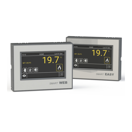
1.2. Identificazione prodotto 1.2. Product Identification I cronotermostati SMARTWEB e SMARTEASY The SMARTWEB and SMARTEASY chrono- sono identificabili mediante la targhetta di rico- thermostats can be identified by the nameplate noscimento posizionata sul lato frontale dell’ap- affixed to the front of the equipment and by the parecchio e tramite la targhetta dati all’esterno label applied to the outside of the packaging. -
Page 9: Produktbezeichnung
1.2. PRODUKTBEZEICHNUNG 1.2. Identification du produit Die Raumtemperaturregler SMARTWEB und Les thermostats programmables SMARTWEB SMARTEASY sind anhand des Kennschilds et SMARTEASY peuvent être identifiés grâce à auf der Vorderseite des Geräts und des Dat- leur étiquette de reconnaissance apposée sur enschilds an der Außenseite der Verpackung le côté... -
Page 10: Manutenzione
• Non utilizzare i tubi del gas come messa adequately protected a terra di apparecchi elettrici • Do not use the gas pipes to earth electrical • Non appoggiare alcun oggetto sopra equipment l’apparecchio • Do not place any object over the equipment •... -
Page 11: Wartung
• Gasleitungen nicht zur Erdung elektrischer mosphériques (pluie, soleil, etc.), s’il n’est Geräte verwenden. pas convenablement préparé • Keine Gegenstände auf dem Gerät • Ne pas utiliser les tuyaux du gaz comme abstellen/-legen. mise à la terre d’appareils électriques • Betriebstemperatur: -15°C bis +60°C •... -
Page 12: Alimentazione Del Sistema
• Completa gestione dei parametri di fun- • Option to install up to 3 remote probes zionamento delle schede degli apparecchi in addition the the probe on board of the collegati machine • Possibilità di installare fino a 3 sonde •... -
Page 13: Alimentation Du Système
rameter der Prozessoren der angeschloss- • Gestion complète des paramètres de fonc- enen Geräte. tionnement des cartes des appareils reliés • Möglichkeit der Installation von bis zu 3 • Possibilité d’installer jusqu’à 3 sondes à Raumfühlern zusätzlich zu den im Gerät distance en plus de celle présente dans montierten. -
Page 14: Istruzioni Per L'utente
4. ISTRUZIONI PER L’UTENTE Le istruzioni contenute nel presente manuale sono re- lative ai controlli remoti 10:15 HOME Lun 01 Gen SMARTWEB e SMARTEASY 20.0 che utilizzano il firmware °C aggiornato alla versione 2.15 (Par. 5.2.7) SET: OFF 4.1. Schermata HOME Il controllo remoto utilizza un display LCD TFT a colori da 4,3”... -
Page 15: Anweisungen Für Den Benutzer
4. USER’S 4. ANWEISUNGEN FÜR 4. INSTRUCTIONS INSTRUCTIONS DEN BENUTZER POUR L’UTILISATEUR The instruction provided Die in diesem Handbuch Les instructions contenues in this manual related to enthaltenen Anleitungen dans le présent manuel sont SMARTWEB and SMART- beziehen sich auf die Fern- relatives aux commandes EASY remote controls which bedienungen SMARTWEB... - Page 16 Set-point Attivo/i Active Set-point/s Allarmi Alarms Generatore in allarme Heater in alarm mode Perdita dati memoria Memory data lost Anomalia di rete Network fault 10:15 HOME Lun 01 Gen 10:15 HOME Mon 01 Jan 20.0 20.0 °C °C SET: 18.0°C SET 18.0°C 000 % 000 %...
- Page 17 Gültige/r Sollwert/e Set-point actif(s) Fehlermeldungen Alarmes Gerätefehler Générateur en état d'alarme Perte de données de la Speicherdatenverlust mémoire Netzstörung Anomalie de réseau 10:15 HOME Lun 01 Gen 10:15 ACCUEIL Lun 1 Janv 20.0 20.0 °C °C SET: 18.0°C RÉGLAGE: 18.0°C 000 % 000 % Betriebszustand...
-
Page 18: Funzionamento
5. FUNZIONAMENTO 5.1. Menù principale 10:15 HOME Lun 01 Gen Premendo il tasto nella 20.0 schermata principale (HOME) °C è possibile accedere al menù principale del cronotermostato. SET: 18°C Il menù è composto dalle se- guenti sezioni: FASCE ORARIE MODO IMPOSTAZIONI REGOLAZIONE HYBRIDO (solo in caso di... -
Page 19: Fonctionnement
5. OPERATION 5. FUNKTIONSWEISE 5. FONCTIONNEMENT 5.1. Main Menu 5.1. Hauptmenü 5.1. Menu principal By pressing the key in the Über die Taste auf dem En appuyant sur la touche main screen (HOME) the main Startbildschirm (HOME) wird de l’écran principal (HOME), menu of the chronothermostat das Hauptmenü... -
Page 20: Impostazioni
Premendo il pulsante corrispondenza della voce di 10:15 MENU Lun 01 Gen uno dei vari menù si accede al relativo sotto-menù. Premendo il plsante in cor- rispondenza della voce di uno dei vari sotto-menù si accede alle impostazioni del relativo sotto-menù. -
Page 21: Configurations
By pressing the key on an Mit der Taste neben den En appuyant sur la touche item of one of the menus, the Punkten eines der verschiedenen au niveau de l’élément d’un des associated submenu can be Menüs wird das entsprechende différents menus, on accède au accessed. -
Page 22: Ora
5.2.2. Ora Procedere alla regolazione 10:15 Lun 01 Gen dell’ora come descritto sopra per la data. 5.2.3. Giorno In questa sezione è possibile selezionare il giorno corrispon- dente alla data sopra inserita. Selezionare il giorno deside- rato, premere il tasto “OK” per confermare ed uscire. -
Page 23: Heure
5.2.2. Time 5.2.2. Uhrzeit 5.2.2. Heure Change the time by following Die Uhrzeit wird wie oben Procéder au réglage de l’heure the above instructions for the für das Datum beschrieben comme décrit ci-dessus pour date. eingestellt. la date. 5.2.3. Day 5.2.3. -
Page 24: Info
in corrispondenza della voce 10:15 MENU Lun 01 Gen “SCREENSAVER”, nel menù “IMPOSTAZIONI”. Regolare il valore del ritardo come de- siderato e confermare con il tasto “OK”. 5.2.7. Info Il menù “INFO” permette di ve- rificare la versione corrente del firmware installato sul cronoter- mostato che si sta utilizzando. -
Page 25: Network Configuration
DE VEILLE» dans le menu as desired and confirm it by Menü „EINSTELLUNGEN“ pressing “OK”. abgerufen. Zeitspanne wie «PARAMETRAGE». Régler la gewünscht einstellen und mit valeur de délai comme désiré et „OK“ bestätigen. confirmer avec la touche «OK». 5.2.7. Info 5.2.7. - Page 26 NB: è importante ricordare che gli indirizzi delle schede 10:15 Sistema Lun 01 Gen sulle macchine collegate al comando remoto, devono RS485 obbligatoriamente essere impostati partendo da 1 fino Ethernet al numero “n” impostato nella configurazione di rete, senza Configurazione Impianto omettere nessun numero della sequenza.
- Page 27 NB: it must be remembered Anm.: Beachten Sie bitte, NB : il est important de rap- that the addresses of the dass die Adressen auf den peler que les adresses des PCBs on the machines con- Prozessoren der an die Fern- cartes sur les machines nected to the remote control bedienung angeschlossenen...
- Page 28 cessario premere nuovamente il tasto “OK” per confermare le 10:15 Sistema Lun 01 Gen modifiche effettuate all’interno del menù “RS485”. Premendo RS485 il tasto invece si uscirà dal menù senza apportare alcun Ethernet salvataggio. Configurazione Impianto 5.3.2. Ethernet (solo vers. SMARTWEB) Reset Impostazioni Iniziali Premendo il pulsante in cor-...
- Page 29 again to confirm the changes muss man erneut auf „OK“ tip- d’appuyer à nouveau sur la touche made inside the “RS485” pen, um die im Menü „RS485“ «OK» pour confirmer les modifi- durchgeführten Änderungen cations effectuées à l’intérieur du menu. If, however, the zu speichern.
-
Page 30: Configurazione Impianto
NB: Per modificare i parametri all’interno delle sezioni: “INDI- 10:15 Sistema Lun 01 Gen RIZZO LOCALE”, “GATEWAY” e “NETMASK”, è necessario RS485 selezionare uno dei campi di immissione per attivarlo, can- Ethernet cellare il valore contenuto con il tasto e successivamente Configurazione Impianto inserire il valore desiderato. -
Page 31: Plant Configuration
NB: To change the parameters Anm.: NB : Pour modifier les paramè- Zur Änderung der Param- eter innerhalb der Abschnitte: inside the sections: “LOCAL tres à l’intérieur des sections : „LOKALE ADRESSE“, „GATE- ADDRESS”, “GATEWAY” and Pour «ADRESSE LOCALE», WAY“ und „NETMASK“ wählt “NETMASK”, select the data «GATEWAY»... - Page 32 NB: al primo avvio del crono- termostato, e ogni qualvolta dovesse verificarsi una per- dita di memoria, la selezione 10:15 Caldaie Lun 01 Gen di default sarà impostata su “Nessuno”. Sarà quindi neces- N. Slave sario procedere ad una nuova configurazione.
- Page 33 NB: when the chronothermostat Anm.: beim ersten Einschalten NB: au premier démarrage du is first started, and every time des Raumtemperaturreglers thermostat programmable, et a loss of memory occurs, the und nach jedem eventuellen chaque fois que l’on constate default selection will be set to Speicherverlust ist die Stand- une perte de mémoire, la sélec- “None”.
- Page 34 Una volta entrati nel sotto-menù “GESTIONE SONDE”, selezio- 10:15 Gestione Sonde Lun 01 Gen nando l’ingresso desiderato, si accede alla pagina di scelta del NTC_On_Board T_RIF tipo di lettura di temperatura da associare a quell’ingresso (se AN1_Ext NONE collegato). AN2_Ext NONE NB: il tipo di lettura di tempe- ratura associabile ai 4 ingressi...
-
Page 35: Reset Original Setting
After entering the “PROBES Im Untermenü „SENSOREIN- Après être entré dans le sous- MANAGEMENT” submenu, by STELLUNG“ wird nach Anwahl menu «GESTION SONDES» selecting the desired input, the des gewünschten Eingangs en sélectionnant l’entrée dé- temperature reading type selec- die Seite zur Auswahl der dem sirée, on accède à... -
Page 36: Reset Impostazioni Iniziali
5.3.4. Reset impostazioni 10:15 Sistema Lun 01 Gen iniziali RS485 Premendo il pulsante corrispondenza della voce “RE- Ethernet SET IMPOSTAZIONI INIZIALI”, all’interno del menù “SISTEMA” Configurazione Impianto si accede al sotto-menù di reset del sistema, attraverso il quale è possibile scegliere di reset- Reset Impostazioni Iniziali tare la sola programmazione del menù... -
Page 37: Reset Original Setting
5.3.4. Reset original setting 5.3.4. Rücksetzung auf die 5.3.4. Réinitialisation des Werkseinstellung configurations initiales By pressing the key on the “RESET ORIGINAL SET- Mit der Taste neben En appuyant sur le bouton TING” item inside the “SYS- „RÜCKSETZUNG AUF WERK- au niveau de l’élément «RESET TEM”... -
Page 38: Fasce Orarie
5.4. Fasce orarie Attraverso questo menù è pos- 10:15 MENU Lun 01 Gen sibile programmare i set-point e i relativi periodi per il funzio- namento “AUTOMATICO” del cronotermostato. Per accedere al menù “FASCE ORARIE” premere il tasto , nel menù principale. -
Page 39: Time Slots
5.4. Time Slots 5.4. Timer 5.4. Tranches horaires By using this menu, the set- Mit diesem Menü kann man die En utilisant ce menu, il est possible points and the associated time Sollwerte und die entsprech- de programmer les set-points ainsi ranges for the chronothermostat enden Zeiten des „AUTOMA- que les périodes relatives de fonc-... - Page 40 dell’anno, rappresentati dalle tre fasce P1, P2 e P3. Con i 10:15 Calendario Lun 01 Gen relativi tasti in corrispon- denza delle 3 fasce si entra Prog. Calendario nella pagina di modifica della fascia corrispondente, che Prog. Vacanze permette di impostare l’inizio e la fine della fascia stessa.
- Page 41 page can be accessed, where tellt. Mit den entsprechenden P2 et P3. Avec les touches relatives the start and end of that time Tasten neben den drei au niveau des 3 tranches, on range can be set. By press- Zeiträumen ruft man die Seite entre dans la page de modification ing the “ENABLE/DISABLE”...
- Page 42 5.4.2. Programmazione fasce orarie 10:15 Fasce Orarie Lun 01 Gen Questo menù permette di impostare il periodo di funzio- Calendario namento all’interno di fasce orarie definite per ogni giorno Prog. Fasce Orarie della settimana, durante le quali le macchine saranno pro- Set.
-
Page 43: Programming The Time Ranges
5.4.2. Programming the Time 5.4.2. Programmierung der 5.4.2. Programmation des Slots Schaltzeiten tranches horaires This menu allows the user to Dieses Menü ermöglicht die Ce menu permet de configurer set the operating period within Einstellung der Betriebszeit la période de fonctionnement the time ranges for each day innerhalb von Schaltzeiten für pendant les tranches horaires... - Page 44 sotto-menù di programmazio- ne. Per ogni giorno della set- 10:15 Lunedì Lun 01 Gen timana è possibile definire fino a cinque differenti fasce orarie (da F1 a F5) anche discontinue tra loro: la loro programmazione avviene impostando, per ogni fascia, l’ora di inizio, l’ora di fine e il set-point desiderato.
- Page 45 chronothermostat will automati- man für jeden Zeitraum die An- de définir jusqu’à cinq différentes cally position itself to N=OFF, fangs- und die Enduhrzeit sowie tranches horaires (de F1 à F5) After setting the time ranges den Sollwert einstellt. In den même discontinues entre elles for the selected day, confirm Stunden ohne eine aktivierte...
-
Page 46: Set Temperature
5.4.3. Set temperature Premendo il pulsante 10:15 Fasce Orarie Lun 01 Gen corrispondenza della voce “SET. TEMPERATURE”, nel Calendario menù “FASCE ORARIE”, è pos- sibile accedere al sotto-menù di Prog. Fasce Orarie configurazione dei set-point di funzionamento della modalità Set. Temperature “AUTOMATICO”. -
Page 47: Set Temperatures
5.4.3. Set Temperatures 5.4.3. Temperatursollwerte 5.4.3. Réglage des tempéra- tures By pressing the key on the Mit der Taste neben „TEM- “TEMPERATURE SET” item PERATURSOLLWERTE” im En appuyant sur le bouton in the “TIME SLOTS” item, the Menü „TIMER” gelangt man au niveau de l’élément «POINT “AUTOMATIC”... -
Page 48: Modo Di Funzionamento
5.5. Modo di funzionamento Questo menù permette di sele- 10:15 MENU Lun 01 Gen zionare il modo di funzionamen- to e la modalità di funzionamen- to degli apparecchi collegati al cronotermostato. Per accedere al menù “MODO” premere il ta- sto (B) , nel menù... -
Page 49: Operating Mode
5.5. Operating Mode 5.5. Betriebsart 5.5. Mode de fonctionnement This menu allows the user to Dieses Menü ermöglicht die Ce menu permet de sélectionner select the operating mode of all Auswahl der Betriebsart und le mode de fonctionnement ainsi the equipment connected to the der Funktionsweise der an que la modalité... - Page 50 determinato periodo, secondo il seguente schema: 10:15 Modo Funzionamento Lun 01 Gen Durata: Modalità Riscaldamento 2h - 4h - 6h - 8h - 12h - Day - Continuo (Day = 24 h; Continuo Manuale = sempre) Temperatura: Fasce Orarie set-point di temperatura deside- rata (range -10,0°C;...
- Page 51 temperature for that period of für jenen bestimmten Zeitraum lequel il est demandé de config- time, according to the following nach folgendem Schema: urer la durée de fonctionnement diagram: ainsi que la température désirée Dauer: pour cette période déterminée Duration: 2h - 4h - 6h - 8h - 12h - Day - selon le schéma suivant: 2h - 4h - 6h - 8h - 12h - Day -...
-
Page 52: Modo Automatico
Funzionamento manuale OFF: tutti gli apparecchi collegati al 10:15 MENU Lun 01 Gen cronotermostato, se preceden- temente in funzione, inizieranno il ciclo di spegnimento. Nella schermata principale verrà vi- sualizzata l’icona “MANUALE” e l’icona “OFF” (*) La modalità VENTILAZIONE è attiva solamente per i genera- tori d’aria calda. -
Page 53: Mode Automatique
Handbetrieb OFF: icon will be displayed. Alle an den Raumtempera- ATTEINT» s’affichera. OFF manual operation: turregler angeschlossenen Geräte beginnen, sofern sie all the pieces of equipment con- Fonctionnement manuel DÉS- zuvor in Betrieb waren, den nected to the chronothermostat, ACTIVÉ Ausschaltzyklus. - Page 54 Funzionamento automatico COMFORT: le macchine colle- 10:15 Modo Funzionamento Lun 01 Gen gate al cronotermostato funzio- nano, in riscaldamento oppure Modalità Riscaldamento in ventilazione, in funzione dei set-point impostati (Par. 5.4.3) Manuale e della temperatura ambiente rilevata. Fasce Orarie Funzionamento automatico Off Temperatura ECONOMY: le macchine colle- gate al cronotermostato funzio-...
-
Page 55: Temporary Off
COMFORT automatic opera- COMFORT-Automatikbetrieb: Fonctionnement automatique CONFORT: les machines tion: the machines connected to die an den Raumtempera- the chronothermostat operate, turregler angeschlossenen reliées au thermostat program- either in heating or ventilation Geräte laufen im Heiz- oder mable fonctionnent en mode mode, according to the selected Lüftungsbetrieb, je nach den chauffage ou ventilation en... - Page 56 Dopo aver selezionato il periodo di tempo desiderato, tra quelli 10:15 HOME Lun 01 Gen elencati sopra, confermare la 20.0 selezione con il tasto “OK”. °C Durante il funzionamento in off temporaneo, all’interno della SET: 18°C schermata principale verrà vi- 000 % sualizzata l’icona relativa 5.5.4.
- Page 57 desired length of time amongst gewünschten Zeitraums unter sous-menu relatif. Après avoir those listed above, confirm the den oben aufgelisteten, diese sélectionné la période désirée selection by pressing “OK”. Wahl mit „OK“ bestätigen. parmi celles listées ci-dessus, During the temporary off opera- Während des Betriebs im confirmer la sélection avec la tion, the main screen will display...
-
Page 58: On/Off
5.6. Regolazione In questo menù è possibile 10:15 MENU Lun 01 Gen selezionare e configurare il tipo di regolazione con la quale si desidera che il cronotermostato lavori. Per accedere al menù “REGOLAZIONE” premere il tasto (D) , all’interno del menù... -
Page 59: Adjust
5.6. Adjust 5.6. Einstellungen 5.6. Réglage : This menu allows the user to In diesem Menü kann man die Dans ce menu, il est possible select and set up the controller gewünschte Art der Regelung de sélectionner et de configurer to be used by the chronother- für den Raumtemperaturregler le type de réglage avec lequel... -
Page 60: Pid
5.6.2. PID Selezionando la regolazione 10:15 MENU Lun 01 Gen “PID” (alla pressione del tasto corrispondente) il cronoter- mostato accenderà e spegnerà le macchine con la stessa logica del sistema “ON/OFF”, ma ne modulerà la potenza in relazio- ne della temperatura ambiente rilevata, secondo la logica del sistema PID (proporzionale- intergrale-differenziale), otte-... -
Page 61: Pid
5.6.2. PID 5.6.2. PID 5.6.2. PID By selecting the “PID” controller Wählt man „PID“-Regelung En sélectionnant le réglage (über die entsprechende Taste «PID» (en appuyant sur la (by pressing the associated key) the chronothermostat will ), schaltet der Raumtemper- touche correspondante), switch the machine on and off aturregler die Geräte mit dersel-... - Page 62 variazioni saranno molto lente, al contrario, se invece si control- 10:15 Lun 01 Gen lano temperaure di processo, le variazioni saranno più veloci. I parametri per il controllo di temperatura ambiente sono 0,05 i seguenti (questi potrebbero differire dai parametri impostati di default): sec.
- Page 63 controlled, variations will will Steuerung ab: bei der Steu- ambiante, les variations seront be faster. erung einer Raumtemperatur très lentes ; en revanche, si on The room temperature control sind die Änderungen sehr contrôle les températures de parameters are as follows (they langsam, bei der Steuerung processus, les variations seront could be different from the de-...
-
Page 64: Cascata
alla macchina direttamente riportata sulla schermata prin- 10:15 MENU Lun 01 Gen cipale “HOME”. Le regolazioni “PID” e “ON/ OFF” saranno sempre subor- dinate alla regolazione limite imposta sulla macchina secon- do l’ST1 e il valore rilevato dalla sonda NTC di riferimento (per informazioni relative a questo tipo di regolazione vedere il ma- nuale della macchina abbinata... -
Page 65: Kaskade
The “PID” and “ON/OFF” con- „PID“ und „ON/OFF“-Regelung afficher le pourcentage instan- trollers will always be subject to sind immer der am Gerät nach tané de puissance envoyé à the maximum value set on the ST1 eingestellten Grenzrege- la machine immédiatement machine according to the ST1 lung und dem von Referenz- reporté... - Page 66 nel menù “CONFIGURAZIONE IMPIANTO” (Par. 5.3.3). 10:15 Cascata Lun 01 Gen NB: le voci “N° SLAVE” e “VA- Valore Inserzione LORE INSERZIONE” risultano evidenziate in blu perchè in sola DIFF_Insert visualizzazione. Tempo Ins. sec. Supponendo di avere 4 caldaie in cascata, e un differenziale di Rotazione Inserimento Slave 5, la prima caldaia viene inserita quando la richiesta supera il...
- Page 67 “PLANT CONFIGURATION” der im Menü „ANLAGENKON- effectuer la division correspond (Par. 5.3.3). FIGURATION“ (Abschn. 5.3.3) au nombre de slaves contrôlées eingegebenen Anzahl der ges- et il s’agit du nombre saisi dans teuerten Slaves. le menu «CONFIGURATION NB: the “N. SLAVE” and “IN- DE L’ÉQUIPEMENT»...
-
Page 68: Hybrido
6. HYBRIDO Quando il comando remoto 10:15 MENU Lun 01 Gen viene utilizzato per controllare un impianto funzionante con sistema Hybrid è necessario che questo venga configurato a tale scopo. Per effettuare questa operazione seguire le indicazioni riportate nel para- grafo 5.3.3. -
Page 69: Hybrid
6. HYBRIDO 6. HYBRID 6. HYBRIDE When the remote control is used Bei Verwendung der Fernbe- Lorsque la commande à distance to control equipment operating dienung zur Steuerung einer est utilisée pour contrôler un with a Hybrid system, it must mit Hybrid-System betriebenen équipement fonctionnant avec configured for this purpose. -
Page 70: Gestione Cpu-Smart
7. GESTIONE CPU- SMART 10:15 HOME Lun 01 Gen Attraverso questo menù è 20.0 possibile accedere alle schede °C CPU-SMART di ogni singola macchina collegata al comando SET: 18°C remoto. E’ possibile visualizzare e/o modificare tutti i parametri 000 % di ogni scheda CPU, visualiz- zare lo storico dei fault di ogni macchina e i suoi stati di fun-... -
Page 71: Alarms Reset
7. CPU-SMART 7. VERWALTUNG CPU- 7. GESTION CPU- MANAGEMENT SMART SMART This menu allows the user to In diesem Menü erhält man Par le biais de ce menu, il est access the CPU-SMART PCBs Zugang zu den CPU-SMART- possible d’accéder aux cartes for each machine connected Prozessoren jedes einzel- CPU-SMART de chaque machine... - Page 72 spondenza della voce “ALARM RESET”. Attendendo qualche 10:15 CPU - 2 Lun 01 Gen istante l’indicazione di allarme passerà dal colore rosso (al- Reset Allarmi larme in corso) a quello giallo (indicando il procedimento di Visualizzazione Parametri reset) per tornare al colore verde (allarme rientrato).
-
Page 73: View Cpu Parameters
item. By waiting a few seconds, zurücksetzen, indem man auf sur la touche au niveau de the alarm indication will go from die Taste neben „STRUN- l’alarme «RESET ALARMES». red (current alarm) to yellow GEN RESET“ tippt. Nach einem En patientant quelques instants, (by showing the resetting pro- Moment erscheint die rote Fe- l’indication d’alarme passera de la... - Page 74 NB: una volta inserita la pas- sword per il sotto-menù “R/W 10:15 CPU - 2 Lun 01 Gen PARAMETRI” corrispondente ad una qualsiasi delle schede Reset Allarmi CPU-SMART collegate, questa rimarrà attiva anche per le altre Visualizzazione Parametri schede CPU collegate, fino a quando non si uscirà...
- Page 75 NB: after entering the password Anm.: Nach Eingabe des Pass- NB: après avoir saisi le mot de for the submenu “R/W PARAM- worts für das Untermenü „ARAM. passe pour le sous-menu «R/W ETERS” matching any of the SCREIBEN/LESEN“ einer be- PARAMÈTRES»...
- Page 76 8. ALLARMI Nella schermata principale 10:15 HOME Lun 01 Gen 20.0 (“HOME”) del cronotermostato possono essere visualizzati tre °C differenti tipologie di allarme: SET: 18°C • Anomalia di rete 000 % • Macchina in allarme • Errore di programma- zione/Perdita dati memoria Flash La segnalazione “Anomalia di rete”...
-
Page 77: Alarms
8. ALARMS 8. FEHLERMELDUNGEN 8. ALARMES The main screen (“HOME”) of Auf der Hauptbildschirmseite D a n s l ’ é c r a n p r i n c i p a l the chronothermostat displays („HOME“) des Raumtempera- («HOME») du thermostat pro- the three different types of turreglers können drei ver-... -
Page 78: Reset Degli Allarmi
Un’incremento continuo indica che la scheda non comunica 10:15 CPU-Smart Lun 01 Gen con il cronotermostato, al con- trario, un’incremento saltuario Tout indica che alcune volte manca la comunicazione tra scheda e 0008 comando remoto, ma questo non pregiudica il corretto fun- 0000 zionamento del sistema. -
Page 79: Reset Alarms
A continuous increase indicates Eine kontinuierliche Zunahme communication entre la carte that the PCB does not com- ist ein Zeichen dafür, dass de l’appareil en question et la municate with the chronother- der Prozessor nicht mit dem commande à distance. mostat;... -
Page 80: Collegamenti Elettrici
9. COLLEGAMENTI ELETTRICI La comunicazione tra il crono- termostato e la/e macchina/e avviene collegando alla/e scheda/e CPU-SMART a bordo della/e macchina/e stessa/e Ethernet due cavi di commutazione MOD-BUS, mentre l’alimenta- zione elettrica del comando va effettuata alimentando i morsetti “+VIN” e “GND”, dello stesso, con corrente continua 12Vdc (+10%/-15%). -
Page 81: Electrical Connections
9. ELECTRICAL 9. STROMANSCHLÜSSE 9. BRANCHEMENTS CONNECTIONS ÉLECTRIQUES Die Übermittlung zwischen Communication between the La communication entre le ther- Raumtemperaturregler und chronothermostat and the mostat programmable et la/les dem/den gesteuerten Gerät(en) machine/s occurs by connect- machine(s) a lieu en reliant à erfolgt, indem man an den/die ing to the CPU-SMART PCB/ la/aux carte(s) CPU-SMART à... - Page 82 Per collegare elettricamente il comando remoto e la/e scheda/e CPU-SMART effet- tuare le seguenti operazioni: Collegare i cavi di comu- nicazione MOD-BUS dai morsetti “A+” e “B-”, del connettore M1, del coman- do remoto rispettivamente ai morsetti “D+” e “D-” del connettore CN04 della scheda CPU-SMART.
- Page 83 To electrically connect the Fernsteuerung des Kontakts retiré pour le contact à distance. remote control and the CPU- entfernt werden muss. SMART PCB/s, proceed as Pour relier électriquement la follows: Zum Anschluss der Fernbe- commande à distance et la/les dienung mit dem/den CPU- carte(s) CPU-SMART, effectuer Connect the MOD-BUS SMART-Prozessor(en) wie folgt...
- Page 84 NB: il comando remoto suppor- ta sonde NTC da 10 KΩ tipo β 3435K. Impostare i corretti indirizzi dei generatori utilizzando gli switch presenti sul- le schede CPU-SMART, come indicato nell’esem- pio a fianco. NB: il numero dell’indirizzo si ottiene sommando i valori corrispondenti alla posizione degli switch.
- Page 85 NB: the remote control sup- Anm.: die Fernbedienung funk- NB: la commande à distance ports 10 KΩ type β 3435K NTC tioniert mit NTC-Fühlern mit 10 est compatible avec les sondes probes. KΩ und β-Wert 3435. NTC de 10 KΩ type β 3435 K. Set up the correct address- Korrekte Adressen der Configurer les adresses...
-
Page 86: Schema Di Collegamento Elettrico
9.1. Schema di collegamento elettrico CPU-SMART # 1 +12V Collegamento MOD-BUS Collegamento alimentazione Contatto ON/OFF remoto +VIN Ingresso Digitale ID2 (NON implementato) Sonda esterna NTC1 - op- zionale (cod. G07202) Sonda esterna NTC2 - op- zionale (cod. G07202) Sonda esterna NTC3 - op- zionale (cod. -
Page 87: Wiring Diagram
9.1.Wiring Diagram 9.1. Anschluss-Schaltplan 9.1. Schéma du branchement électrique CPU-SMART # 2 CPU-SMART # 3 CPU-SMART # n +12V +12V +12V MOD-BUS connection MOD-BUS-Verbindung Raccordement MOD-BUS Power supply connection Versorgungsanschluss Raccordement à l’alimentation Ferngesteuerter ON/OFF- Remote ON/OFF contact Contact ON/OFF à distance Kontakt ID2 Digital Input IDigital-EingangID2... - Page 88 20060 Pessano con Bornago (MI) - Italia Casella Postale 69 Via Isonzo, 1 (ex Via Provinciale 85) Cod.Fisc. - P.IVA IT 08767740155 : +39 02 9596931 : apen@apengroup.com : www.apengroup.com Fax: +39 02 95742758 SMART cod. HG0060.00 W ed.A-1511 Il costruttore si riserva la facoltà di apportare le necessarie modifiche ai prodotti o alla documentazione.