Publicité
Les langues disponibles
Les langues disponibles
Liens rapides
INSTALLATION
INSTRUCTIONS
1
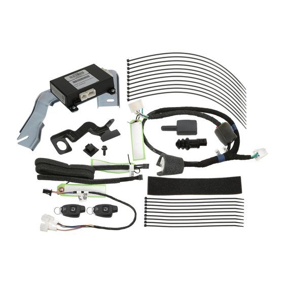
KIT CONTENTS
Remote Engine Start
Control Module w/ Mounting
Bracket
Quantity=1
Remote Engine Start
Antenna Pod and Harness
Quantity=1
2
TOOLS REQUIRED
Phillips Screwdriver
Short and Standard
Ratchet, 10mm and 12mm Sockets,
Extension and U-Joint
3
MEANING OF CHARACTERS
CAUTION: DO NOT SECURE ANY REMOTE START HARNESSES / MODULES TO ANY YELLOW HARNESSES /
CONNECTORS (AIRBAG SYSTEM) IN THE VEHICLE.
PART NUMBER
ISSUE
H001SAL002
Remote Engine Start Ignition
Wire Harness
Quantity=1
NOTE: All vehicle doors, hood, trunk or rear gate must be closed prior to activating the remote engine start
system. Any open entry point will prevent starting or cause the system to shut down.
Upon successful activation, the remote start fob will fl ash and beep once**, the horn will honk once and the side
marker lights, tail lights and parking lights will fl ash once. The system will check certain safety preconditions before
starting and if all conditions are met, the engine will start within fi ve (5) seconds. After the engine starts, the remote
start fob will fl ash and beep twice**, the horn will honk once and the side marker lights, tail lights and parking lights
will fl ash once. While the engine is idling via the remote engine start system, the remote start fob will continue to fl ash
once every three (3) seconds, the side marker lights, tail lights and parking lights will remain illuminated and the power
window switches will be disabled. The engine will continue to run for fi fteen (15) minutes unless one of the safety
parameters below is triggered. The system also has a timer that will allow the system to operate for a maximum of
twenty (20) minutes (under multiple remote start activations). Using the ignition key to turn on the ignition resets the
twenty (20) minute timer.
WARNING: / AVERTISSEMENT
If the engine turns over but does not start (or starts and stalls) the remote engine start system will power off and then
attempt to start the engine three (3) additional times. The system will not attempt to restart the engine if it determines
a vehicle malfunction is preventing it from starting. If the engine does not start after the three (3) additional attempts,
This vehicle is equipped with a remote controlled engine starter.
the remote engine start request will be aborted.
Remote Start Safety Parameters
To reduce the risk of serious Injury or death, switch engine starter
For safety and security reasons, the system will fail to start or shut down the engine during remote start operation if
any of the following occur:
system into service mode and disconnect the vehicle battery
•
The remote start system has operated for twenty (20) minutes between ignition key cycles
before performing any service on the vehicle.
•
The remote start system "Service Mode" is engaged
•
Any of the vehicle's doors, trunk or rear gate are open / opened
Ce véhicule est doté d'un démarreur à distance. Pour réduire les
•
The vehicle's hood is open
risques de blessures graves ou mortelles, mettre le démarreur à
•
The ignition key is resting in the ignition cylinder
distance en mode service et débrancher la batterie du véhicule
•
The transmission shifter is not in the "park" position
•
The vehicle's brake pedal is depressed before the vehicle ignition switch is turned "on"
avant d'effectuer des travaux d'entretien sur celui-ci.
•
The vehicle's engine idle speed has reached a level over 3,500 RPM (this will cause the vehicle to shutdown)
•
The vehicle's security system is triggered by opening the door or rear gate (if the security system is armed at the
time of remote start activation)
In addition to the items above, if the vehicle's engine management system determines there is a safety risk due to a
vehicle related problem, the vehicle will shut down and the vehicle's horn will honk three (3) times.
WARNING: TO AVOID DANGER OF CARBON MONOXIDE, NEVER REMOTE START A VEHICLE IN A CLOSED
SPACE SUCH AS A CLOSED GARAGE.
NOTE: Laws in some communities require that the vehicle be within view of anyone using the Remote Engine
Starter. In some areas, use of the Remote Engine Starter may violate state, provincial or local laws. Before
using the Remote Engine Starter, check your state, provincial and local laws.
* See your owner's manual for more details.
** Provided that the remote start transmitter is within the operating range of the system.
Under Hood
Warning Label
Reference Card
Quantity=1
Quantity=1 English,
Torque Wrench
Alcohol and Towel
: Remove
: Install
: Disconnect
: Connect
: Location of Clip or Screw
DATE
00
24 Jan 2017
PART NUMBER:
DESCRIPTION:
Pre-Arranged
Jumper Wire Harness
Quantity=1
REMOTE START QUICK REFERENCE*
Press
Two (2) Times
Press and Hold
For Two (2) Seconds
Within Three (3) Seconds
Remote Start
Activation
Remote Start
Shutdown
The horn will honk three (3) times and the parking lights will fl ash three (3) times
The horn will honk fi ve (5) times and the parking lights will fl ash fi ve (5) times
The horn will honk six (6) times and the parking lights will fl ash six (6) times
The horn will honk two (2) times and the parking lights will fl ash two (2) times
The horn will honk two (2) times and the parking lights will fl ash two (2) times
The horn will honk two (2) times and the parking lights will fl ash two (2) times
The horn will honk two (2) times and the parking lights will fl ash two (2) times
P/N: 4280561, Rev -
Quick
Tie Wraps
20cm Quantity=9
39cm Quantity=11
1 French
Panel Removal Tool
Wire Cutters
Ruler
SUBARU OF AMERICA
H001SAL002
LONG RANGE TURN START
REMOTE ENGINE START SYSTEM
LEGACY / OUTBACK
Remote Engine Start
Transmitters w/ Warning Tags
Quantity=2
Hood Switch
Foam Tape
Harness Clip
Quantity=1
Quantity=1
SSM III
Diagnostic Interface or
T
: Tighten Torque
: Loosen
: Discard
: Re-use
Hood Safety Switch,
Mounting Bracket &
Mounting Bolt
Quantity=1
Flock Tape
Quantity=4
B
A
SSM IV (DST-i)
Diagnostic Interface
1 OF 19
Publicité

Manuels Connexes pour Subaru H001SAL002


Sommaire des Matières pour Subaru H001SAL002
- Page 1 : Location of Clip or Screw CAUTION: DO NOT SECURE ANY REMOTE START HARNESSES / MODULES TO ANY YELLOW HARNESSES / CONNECTORS (AIRBAG SYSTEM) IN THE VEHICLE. DATE PART NUMBER ISSUE SUBARU OF AMERICA 1 OF 19 H001SAL002 24 Jan 2017...
- Page 2 3. Remove the driver’s side under dashboard fi nisher panel by depressing the three (3) pressure clips and pulling downward. Unplug all connectors attached to the dashboard fi nsher panel. (FIGURE D) FIGURE B FIGURE A FIGURE D FIGURE C PART NUMBER ISSUE DATE SUBARU OF AMERICA 2 OF 19 H001SAL002 24 Jan 2017...
- Page 3 (FIGURE G) NOTE: Rotate the steering wheel to access the Phillips screws on the face of the steering column. FIGURE G DATE PART NUMBER ISSUE SUBARU OF AMERICA 3 OF 19 H001SAL002 24 Jan 2017...
- Page 4 fi lm and dotted black fi lm meet and 25mm (1”) left of the windshield center mark. (FIGURE K) Clean mounting area with alcohol FIGURE K PART NUMBER ISSUE DATE SUBARU OF AMERICA 4 OF 19 H001SAL002 24 Jan 2017...
- Page 5 6. Re-install the airbag tether clip to the A-pillar panel and rotate the panel into place. 7. Re-install the A-pillar panel. PROCEED TO SECTION 7 FIGURE M DATE PART NUMBER ISSUE SUBARU OF AMERICA 5 OF 19 H001SAL002 24 Jan 2017...
- Page 6 FIGURE N 3. Inspect the white protective (non-woven fabric) of the curtain airbag. If the fabric is damaged, the curtain airbag assembly must be replaced. FIGURE P PART NUMBER ISSUE DATE SUBARU OF AMERICA 6 OF 19 H001SAL002 24 Jan 2017...
- Page 7 5. Re-install the airbag tether clip to the A-pillar panel and rotate the panel into place. 6. Re-install the A-pillar panel. FIGURE R FIGURE S DATE PART NUMBER ISSUE SUBARU OF AMERICA 7 OF 19 H001SAL002 24 Jan 2017...
- Page 8 10mm mounting nut to 10.8 Nm +/- 2 Nm (1.10 Kgf-m +/- 0.2 Kgf-m, 8 ft-lbs +/- 1.5 ft-lbs). Mounting Studs FIGURE U FIGURE V PART NUMBER ISSUE DATE SUBARU OF AMERICA 8 OF 19 H001SAL002 24 Jan 2017...
- Page 9 6. Using one (1) of the supplied 20cm tie wraps, bundle and secure any excess pre-arranged jumper harness to the existing vehicle wiring. (FIGURE X) FIGURE X DATE PART NUMBER ISSUE SUBARU OF AMERICA 9 OF 19 H001SAL002 24 Jan 2017...
- Page 10 NOTE: If the RES Kit is equipped with the new Rev A Ignition Harness (Blue tape rings), no modifi cations are necessary. Proceed with the ignition harness installation on Page 11. PART NUMBER ISSUE DATE SUBARU OF AMERICA 10 OF 19 H001SAL002 24 Jan 2017...
- Page 11 3. Using a Phillips screwdriver, remove the two (2) screws securing the large metal bracket to the left side of the steering column. (FIGURE Z) FIGURE Z DATE PART NUMBER ISSUE SUBARU OF AMERICA 11 OF 19 H001SAL002 24 Jan 2017...
- Page 12 (0.41 Kgf-m +/- 0.1Kgf-m, 2.95 ft. lbs. +/- 0.74 ft. lbs.). (FIGURE Z) NOTE: Use care to ensure the screws are not over tightened to prevent damage to the screws. PART NUMBER ISSUE DATE SUBARU OF AMERICA 12 OF 19 H001SAL002 24 Jan 2017...
- Page 13 39cm tie wraps. (FIGURE EE) CAUTION: DO NOT SECURE THE REMOTE ENGINE START IGNITION HARNESS TO ANY YELLOW HAR- NESSES/CONNECTORS (AIRBAG SYSTEM) IN THE VEHICLE. FIGURE EE DATE PART NUMBER ISSUE SUBARU OF AMERICA 13 OF 19 H001SAL002 24 Jan 2017...
- Page 14 CAUTION: DO NOT SECURE THE REMOTE ENGINE START HARNESS TO ANY YELLOW HARNESSES / CONNECTORS (AIRBAG SYSTEM) IN THE VEHICLE. Plastic Wire Harness Shroud FIGURE FF PART NUMBER ISSUE DATE SUBARU OF AMERICA 14 OF 19 H001SAL002 24 Jan 2017...
- Page 15 5. Torque the mounting bolt to 10.8 Nm +/- 2 Nm (1.10 Kgf-m FIGURE HH +/- 0.2 Kgf-m, 8 ft-lbs +/- 1.5 ft-lbs). A/T Control Module FIGURE JJ FIGURE II DATE PART NUMBER ISSUE SUBARU OF AMERICA 15 OF 19 H001SAL002 24 Jan 2017...
- Page 16 9. 3.6L (6 Cylinder) vehicles - Using one (1) of the supplied 20cm tie wraps, secure the hood switch harness to the factory wiring. (FIGURE MM) FIGURE MM PART NUMBER ISSUE DATE SUBARU OF AMERICA 16 OF 19 H001SAL002 24 Jan 2017...
- Page 17 6. Re-install the left side dashboard panel by engaging fi ve (5) pressure clips. 7. At the end of the installation, insert the Quick Reference Cards into the Owner’s Information Kit. DATE PART NUMBER ISSUE SUBARU OF AMERICA 17 OF 19 H001SAL002 24 Jan 2017...
- Page 18 "Reg Remote Cont. Confirm Ignition Sw On Registration PRESS PRESS PRESS "Remo.con.eng.st "Registering... WAIT Eng Starter Press "Ent" Complete regist.success" Please Wait" Yes: ENT / No: C" PART NUMBER ISSUE DATE SUBARU OF AMERICA 18 OF 19 H001SAL002 24 Jan 2017...
- Page 19 (test) mode fuse is removed, then re-check. PART NUMBER ISSUE DATE SUBARU OF AMERICA 19 OF 19 H001SAL002 24 Jan 2017 4280714 Rev - 1/24/17...
- Page 20 MISE EN GARDE : N’ATTACHEZ JAMAIS LE FAISCEAU OU LE MODULE DE DÉMARRAGE À DISTANCE À UN FAISCEAU JAUNE DU VÉHICULE OU À SON CONNECTEUR (SYSTÈME DE COUSSINS GONFLABLES). DATE NUMÉRO DE PIÈCE VERSION SUBARU OF AMERICA 1 DE 19 H001SAL002 24 janvier 2017...
- Page 21 Débranchez tous les connecteurs fixés au panneau de garniture du tableau de bord. (FIGURE D) FIGURE B FIGURE A FIGURE D FIGURE C NUMÉRO DE PIÈCE VERSION DATE SUBARU OF AMERICA 2 DE 19 H001SAL002 24 janvier 2017...
- Page 22 (FIGURE G) REMARQUE : Tourner le volant pour accéder aux vis Phillips sur la face de la colonne de direction. FIGURE G DATE NUMÉRO DE PIÈCE VERSION SUBARU OF AMERICA 3 DE 19 H001SAL002 24 janvier 2017...
- Page 23 à pois, et à 25 mm (1 po) à gauche de la marque centrale sur le pare-brise. (FIGURE K) Nettoyez la zone de montage avec de l’alcool. FIGURE K NUMÉRO DE PIÈCE VERSION DATE SUBARU OF AMERICA 4 DE 19 H001SAL002 24 janvier 2017...
- Page 24 7. Réinstallez le panneau du montant avant. PASSEZ À LA SECTION 7 FIGURE M DATE NUMÉRO DE PIÈCE VERSION SUBARU OF AMERICA 5 DE 19 H001SAL002 24 janvier 2017...
- Page 25 3. Examinez la toile protectrice blanche (tissu non tissé) du rideau gonflable. Si le tissu est endommagé, le rideau gonflable doit être remplacé. FIGURE P NUMÉRO DE PIÈCE VERSION DATE SUBARU OF AMERICA 6 DE 19 H001SAL002 24 janvier 2017...
- Page 26 5. Réinstallez l’attache de coussin gonflable au panneau FIGURE R du montant avant, puis faites pivoter le panneau pour le remettre en place. 6. Réinstallez le panneau du montant avant. FIGURE S DATE NUMÉRO DE PIÈCE VERSION SUBARU OF AMERICA 7 DE 19 H001SAL002 24 janvier 2017...
- Page 27 10 mm à 10,8 Nm +/- 2 Nm (1,10 kgf-m +/- 0,2 kgf-m, 8 pi-lb +/- 1,5 pi-lb). Tiges de montage FIGURE U FIGURE V NUMÉRO DE PIÈCE VERSION DATE SUBARU OF AMERICA 8 DE 19 H001SAL002 24 janvier 2017...
- Page 28 6. À l’aide d’une (1) attache de 20 cm fournie, regroupez tout faisceau prémonté excédentaire et attachez le tout au câblage existant dans le véhicule. (FIGURE X) FIGURE X DATE NUMÉRO DE PIÈCE VERSION SUBARU OF AMERICA 9 DE 19 H001SAL002 24 janvier 2017...
- Page 29 REMARQUE : Si le nécessaire RES comprend le nouveau faisceau d’allumage de la révision A (anneaux de ruban bleu), aucune modification n’est nécessaire. Passez à l’installation du faisceau d’allumage à la page 11. NUMÉRO DE PIÈCE VERSION DATE SUBARU OF AMERICA 10 DE 19 H001SAL002 24 janvier 2017...
- Page 30 3. À l'aide d'un tournevis Phillips, retirez les deux (2) vis maintenant en place le grand support de métal du côté gauche de la colonne de direction. (FIGURE Z) FIGURE Z DATE NUMÉRO DE PIÈCE VERSION SUBARU OF AMERICA 11 DE 19 H001SAL002 24 janvier 2017...
- Page 31 à 4 Nm +/- 1 Nm (0,41 kgf-m +/- 0,1 kgf-m, 2,95 pi-lb +/- 0,74 pi-lb). (FIGURE Z) REMARQUE : Veillez à ne pas trop serrer les vis pour ne pas les endommager. NUMÉRO DE PIÈCE VERSION DATE SUBARU OF AMERICA 12 DE 19 H001SAL002 24 janvier 2017...
- Page 32 MISE EN GARDE : N’ATTACHEZ AUCUN FAISCEAU DE DÉMARRAGE À DISTANCE DU MOTEUR À UN FAIS- CEAU JAUNE DU VÉHICULE OU À SON CONNECTEUR (SYSTÈME DE COUSSINS GONFLABLES). FIGURE EE DATE NUMÉRO DE PIÈCE VERSION SUBARU OF AMERICA 13 DE 19 H001SAL002 24 janvier 2017...
- Page 33 MISE EN GARDE : N’ATTACHEZ AUCUN FAISCEAU DE DÉMARRAGE À DISTANCE DU MOTEUR À UN FAISCEAU JAUNE DU VÉHICULE OU À SON CONNECTEUR (SYSTÈME DE COUSSINS GONFLABLES). Coquille en plastique du faisceau de câblage FIGURE FF NUMÉRO DE PIÈCE VERSION DATE SUBARU OF AMERICA 14 DE 19 H001SAL002 24 janvier 2017...
- Page 34 5. Serrez le boulon à 10,8 +/- 2 Nm (1,10 +/- 0,2 kgf-m, 8 +/- 1,5 lb-pi). FIGURE HH Module de commande de boîte automatique FIGURE JJ FIGURE II DATE NUMÉRO DE PIÈCE VERSION SUBARU OF AMERICA 15 DE 19 H001SAL002 24 janvier 2017...
- Page 35 – À l'aide d'une (1) attache de 20 cm fournie, attachez le faisceau du contacteur de sécurité du capot au câblage installé en usine. (FIGURE MM) FIGURE MM NUMÉRO DE PIÈCE VERSION DATE SUBARU OF AMERICA 16 DE 19 H001SAL002 24 janvier 2017...
- Page 36 6. Installez le panneau du côté gauche du tableau de bord en engageant les cinq (5) attaches à pression. 7. À la fin de l’installation, glissez la Carte de référence rapide dans le dossier du propriétaire. DATE NUMÉRO DE PIÈCE VERSION SUBARU OF AMERICA 17 DE 19 H001SAL002 24 janvier 2017...
- Page 37 “Subaru Vehicle” SUR ENT Appuyer sur ENT pour SUR ENT SUR ENT other model » (tous (« Enregistrement de (« Véhicule Subaru ») sélectionner Immobi Sys les autres modèles). l’antidémarreur ») (Antidémarreur) APPUYER SUR L'écran SDI affichera : L'écran SDI affichera : L'écran SDI affichera :...
- Page 38 Si la clé peut être retirée, vérifiez si les connecteurs à solénoïde de verrouillage et de carillon de clé sont bien branchés et si le fusible de mode livraison (test) est retiré, puis essayez de nouveau. DATE NUMÉRO DE PIÈCE VERSION SUBARU OF AMERICA 19 DE 19 H001SAL002 24 janvier 2017 4280714 Rév. : 24-01-2017...