MINN KOTA FORTREX Manuel Du Propriétaire
Moteur de pêche à la traîne monté sur proue
Masquer les pouces
Voir aussi pour FORTREX:
- Mode d'emploi (28 pages) ,
- Instructions d'installation (52 pages) ,
- Manuel du propriétaire (62 pages)
Table des Matières
Publicité
Les langues disponibles
Les langues disponibles
Liens rapides
Publicité
Chapitres
Table des Matières
Dépannage

Manuels Connexes pour MINN KOTA FORTREX


Sommaire des Matières pour MINN KOTA FORTREX
- Page 1 FORTREX ® BOW-MOUNT TROLLING MOTOR Owner's Manual...
- Page 2 THANK YOU Thank you for choosing Minn Kota. We believe that you should spend more time fishing and less time positioning your boat. That’s why we build the smartest, toughest, most intuitive trolling motors on the water. Every aspect of a Minn Kota trolling motor is thought out and rethought until it’s good enough to bear our name.
-
Page 3: Table Des Matières
TABLE OF CONTENTS SAFETY CONSIDERATIONS ....................4 WARRANTY ........................5 KNOW YOUR BOAT ......................6 FEATURES ........................7 INSTALLATION ......................... 8 Assembly of Bowguard to Mount ................9 Installing the Mount ....................10 Installing the Gas Spring Pin .................. 13 Placing the Bow-mount Stabilizer ................ -
Page 4: Safety Considerations
WARNING You are responsible for the safe and prudent operation of your vessel. We have designed your Minn Kota product to be an accurate and reliable tool that will enhance boat operation and improve your ability to catch fish. This product does not relieve you from the responsibility for safe operation of your boat. -
Page 5: Warranty
Products purchased outside of the U.S. must be returned prepaid with proof of purchase (including the date of purchase and serial number) to any Authorized Minn Kota Service Center in the country of purchase. -
Page 6: Know Your Boat
KNOW YOUR BOAT Port Starboard Inboard Outboard Keel Port Starboard Gunwale Transom Stern Gunwale Stern Hull 6 | minnkotamotors.com ©2021 Johnson Outdoors Marine Electronics, Inc. -
Page 7: Features
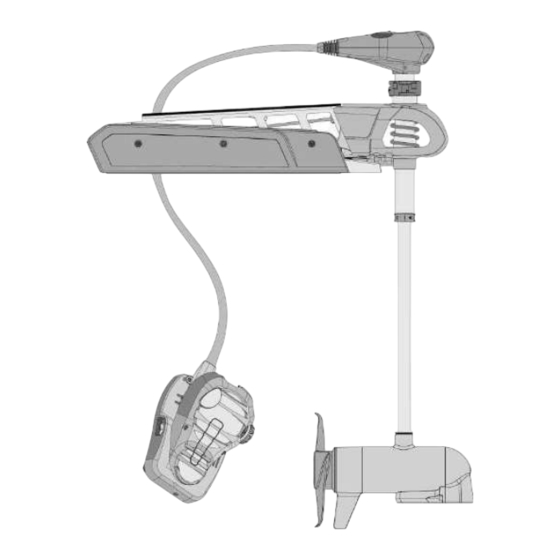
FEATURES Mono-Arm Directional Indicator Design Depth Collar Knob BowGuard 360° ® Breakaway Protection Lift-Assist Lifetime Warranty Momentary On Button Flexible Composite Shaft Constant On Switch Speed Control Cool Quiet Power Motor Heel Block High-Impact Composite Material Propeller NOTICE: Specifications subject to change without notice. This diagram is for reference only and may differ from your actual motor. -
Page 8: Installation
INSTALLING THE FORTREX Your new Fortrex comes with everything you’ll need to directly install it to the boat. This motor can be directly mounted to the boat or coupled with a Minn Kota quick release bracket for ease of mounting and removal. For installation with a quick release bracket, refer to the installation instructions provided with the bracket. -
Page 9: Assembly Of Bowguard To Mount
ASSEMBLY OF BOWGUARD TO MOUNT MOUNTING CONSIDERATIONS It is recommended that the motor be mounted as close to the keel or centerline of the boat as possible. Make sure the area under the mounting location is clear to drill holes and install View accessories nuts and washers. -
Page 10: Installing The Mount
INSTALLING THE MOUNT Align the Keyways on the inside of the BowGuard Pull Grip and Rope Pull Grip and Rope with the End Links on the Mount. Lower the motor Allen Screw Allen Screw assembly straight down until seated. Lock Washer Lock Washer Install the 5/16”... - Page 11 INSTALLING THE MOUNT ITEM(S) NEEDED #20 x 1 Review the mounting considerations at the beginning of the Installation section for proper placement. Place the Mount as close to the centerline or keel of the boat as possible, with the motor in the deployed Mount Mount position, on the deck of the boat.
- Page 12 INSTALLING THE MOUNT Check the placement with the motor in the deployed position. When the motor is in the deployed position, make sure that the Shaft is 1-1/2" out past the Gunwale of the boat. The lower unit, when stowed and deployed must not encounter any obstructions.
-
Page 13: Installing The Gas Spring Pin
INSTALLING THE GAS SPRING PIN ITEM(S) NEEDED #6 x 6 #5 x 6 #4 x 6 Put a 1/4-20 x 2 1/2" Screw (Item #4) in each of the drilled locations. The Screw should pass through the Screw Mount Plate and the boat deck. Place a Flat Washer (Item #5) and then a Nylock Nut (Item #6) at the end of each screw as shown and secure. -
Page 14: Placing The Bow-Mount Stabilizer
The Bow-Mount Stabilizer is not required or Bowguard and reduce bouncing when the motor is stowed and included on the 80lb 45” Fortrex. transported. Attention to detail is needed for successful installation of the stabilizer. We recommend to have the stabilizer bracket installed by a qualified marine installer. - Page 15 Bowguard behind the spring. Secure with a 1/4” Allen Wrench. Tighten to 10 ft lb. NOTICE: The two Lock Washers (Item #16) are not used when installing on the Fortrex. minnkotamotors.com | 15 ©2021 Johnson Outdoors Marine Electronics, Inc.
- Page 16 PLACING THE BOW-MOUNT STABILIZER Measure the proper length of the Aluminum Rod by Stabilizer Stabilizer standing it, with the threaded end down, onto the Bracket Bracket deck surface so that it sits vertically right next to the Stabilizer Bracket. 3/4" 3/4"...
-
Page 17: Mounting The Foot Pedal
MOUNTING THE FOOT PEDAL Once in the correct position, tighten the Jam Nut Top Bumper Top Bumper upwards against the Stabilizer Bracket. This will Stabilizer Stabilizer prevent the Aluminum Rod from turning. Bracket Bracket Install the Top Bumper if there are threads exposed Jam Nut Jam Nut on the Aluminum Rod above the Stabilizer Bracket. -
Page 18: Routing Connection Cables
ROUTING CONNECTION CABLES ROUTING CONNECTION CABLES Please follow these instructions for routing any and all of the cables present for any pre-installed feature that may come with your trolling motor. This routing should be followed no matter the type of connection cable present. Locate the Universal Sonar cable, at the base of the Foot Pedal. -
Page 19: Universal Sonar
UNIVERSAL SONAR Universal Sonar Your trolling motor may be pre-installed with a Universal Sonar transducer system. Universal Sonar is a 2D sonar transducer with a temperature sensor that is integrated into the lower unit of the trolling motor. It has an operating frequency of 83/200 kHz. Connecting this transducer to a compatible fish finder gives you a 2D sonar view of what is happening directly below your trolling motor. - Page 20 14.5’ extension cable is Four Pin Connector Four Pin Connector available to purchase. Minn Kota recommends using the MKR-US2-11. Take the Universal Sonar Extension Cable, if needed, Locking Collar...
-
Page 21: Battery & Wiring Installation
CAUTION These guidelines apply to general rigging to support your Minn Kota motor. Powering multiple motors or additional electrical devices from the same power circuit may impact the recommended conductor gauge and circuit breaker size. If you are using wire longer than that provided with your unit, follow the conductor gauge and circuit breaker sizing table below. -
Page 22: Selecting The Correct The Batteries
Lithium Ion batteries. However, they are specifically designed to run on traditional lead acid batteries (flooded, AMG or GEL). Lithium Ion batteries maintian higher voltages for longer periods of time than lead acid. Therefore, running a Minn Kota trolling motor at speeds higher than 85% for a prolonged peiod could cause permanent damage to the motor. -
Page 23: Connecting The Batteries In Series
CONNECTING THE BATTERIES IN SERIES The negative (-) connection must be connected to the negative terminal of the same battery that the trolling motor negative lead connects to. In the diagrams below this battery is labeled “Low Side” Battery. Connecting to any other trolling motor battery will input positive voltage into the “ground”... - Page 24 CONNECTING THE BATTERIES IN SERIES 36 Volt Systems Three 12 volt batteries are required. The batteries must be wired in series, only as directed in wiring diagram, to provide 36 volts. Make sure that the motor is switched +36 Volts to trolling motor off (speed selector on “0”).
-
Page 25: Motor Wiring Diagram
MOTOR WIRING DIAGRAM FORTREX The following Motor Wiring Diagram applies to all Fortrex Foot Control models. Universal Sonar is an optional feature that may come factory installed. Control Head Indicator Light Fuse Orange Ground Brown Black M- Brown Red M+... -
Page 26: Using & Adjusting The Motor
Be alert for unexpected boat movement when operating the temperatures, which can be increased by an excessively hot Fortrex. The boat may encounter sharp turns and jolts if the operating environment. Use care when handling the Control steering is changed sharply or if broad changes in speed are Head and Foot Pedal to avoid burns or injuries from excessive made while operating. -
Page 27: Stowing And Deploying The Motor
STOWING AND DEPLOYING THE MOTOR STOWING AND DEPLOYING THE MOTOR WARNING When stowing or deploying the motor, keep fingers clear of all hinge and pivot points and all moving parts. Practice proper ergonomics when stowing and deploying the motor to prevent injury. WARNING Moving the motor creates a variety of pinch points. -
Page 28: Motor Adjustments
ADJUSTING THE LOWER UNIT FOR A SECURE STOW MOTOR ADJUSTMENTS MOTOR ADJUSTMENTS Adjusting the Lower Unit for a Secure Stow When the Motor is stowed, the Lower Unit should rest on the Mount Ramps just inside the Motor Rest on the Motor Mount. It is recommended to secure the motor using the following instructions to avoid damage to the motor and shaft from vibrations during transport. -
Page 29: Adjusting The Depth Of The Motor
ADJUSTING THE DEPTH OF THE MOTOR With the motor in the deployed position, firmly grasp the motor Shaft above the Bowguard. Depth Adjustment Locate the Depth Adjustment Knob on the Shaft. Knob Loosen the Depth Adjustment Knob, while holding the Shaft in place, until the Shaft slides freely. Raise or lower the motor to the desired depth. -
Page 30: Installing An External Transducer
INSTALLING AN EXTERNAL TRANSDUCER INSTALLING AN EXTERNAL TRANSDUCER An external transducer is not included with your trolling motor. An external transducer can be installed onto motors that have Universal Sonar or motors that do not have a built in transducer. For more information on Universal Sonar, please visit minnkotamotors.com. Installing an external transducer is not recommended for motors with Built-in MEGA Down Imaging. -
Page 31: Using The Foot Pedal
USING THE FOOT PEDAL CONTROLLING SPEED & STEERING WITH THE FOOT PEDAL Most controls on the Foot Pedal are easy to operate by either foot or hand. Speed Knob Toe End Directional Indicator Momentary On Heel End Button Constant On Switch To Adjust Motor Speed Turn the speed knob clockwise to increase speed and counter-clockwise to decrease speed. -
Page 32: Foot Pedal Adjustments
ADJUSTING THE STEERING CABLE CAUTION Route the Foot Pedal Cable neatly to minimize tripping hazards. Practice proper ergonomics when operating the Foot Pedal to avoid fatigue and prevent injury. FOOT PEDAL ADJUSTMENTS Adjusting the Steering Cable The steering cable tension is pre-set at the factory but, through normal use, may need occasional adjustment. Adjust the tension of the cables by turning the cable Stainless Steel Cable Cable Tension Adjustment Screw... -
Page 33: Service & Maintenance
SERVICE & MAINTENANCE PROPELLER REPLACEMENT TOOLS AND RESOURCES REQUIRED • 9/16” Open End Wrench • Flat Blade Screwdriver INSTALLATION Disconnect the motor from all sources of power prior to changing the propeller. Drive Pin Drive Pin Armature Armature Shaft Shaft Hold the propeller and loosen the Prop Nut with a pliers or a wrench. -
Page 34: Removal Of The Bowguard
SERVICE & MAINTENANCE REMOVAL OF THE BOWGUARD TOOLS AND RESOURCES REQUIRED (2) #3 Phillips screwdrivers Torque Wrench 1/4” Allen Wrench Needle Nose Pliers INSTALLATION Disconnect the Gas Spring WARNING Gas Spring Cylinder Yoke Moving parts can cut or crush. The gas assist lift mechanism is under pressure. -
Page 35: Remove Bowguard From Mount
SERVICE & MAINTENANCE Once the screws are removed, the pin and spacers Outer Arm can be removed from the Upper Cylinder. Now it is safe to remove the motor from the bow mount when the motor is in the deployed position. Gas Spring Cylinder Outer Arm Remove BowGuard From Mount... -
Page 36: General Maintenance
SERVICE & MAINTENANCE GENERAL MAINTENANCE • After use, the entire motor should be rinsed with freshwater. This series of motors is not equipped for saltwater exposure. • The composite shaft requires periodic cleaning and lubrication for proper retraction and deployment. A coating of an aqueous based silicone spray will improve operation. -
Page 37: For Further Troubleshooting And Repair
Authorized Service Centers Minn Kota has over 800 authorized service providers in the United States and Canada where you can purchase parts or get your products repaired. Please visit our Authorized Service Center page on our website to locate a service provider in your area. -
Page 38: Compliance Statements
Minn Kota motors are not subject to the disposal regulations EAG-VO (electric devices directive) that implements the WEEE directive. Nevertheless never dispose of your Minn Kota motor in a garbage bin but at the proper place of collection of your local town council. -
Page 39: Fcc Compliance
COMPLIANCE STATEMENTS FCC COMPLIANCE This device complies with Part 15 of the FCC rules. Operation is subject to the following two conditions: This device may not cause harmful interference. This device must accept any interference that may be received, including interference that may cause undesired operation. Changes or modifi cations not expressly approved by Johnson Outdoors Marine Electronics, Inc. -
Page 40: Parts Diagram And Parts List
PARTS DIAGRAM & PARTS LIST FORTREX - 80/112 LBS THRUST - 24/36 VOLT - 45”/52” SHAFT The parts diagram and parts list provides Minn Kota WEEE compliance disassembly instructions. For more information about where ® you should dispose of your waste equipment for recycling and recovery and/or your European Union member state requirements, please contact your dealer or distributor from which your product was purchased. - Page 41 The Bow-Mount Stabilizer Assembly is not required or included on the 80lb ✖ This part is included in an assembly and cannot be ordered individually. 45” Fortrex. Ì Only available with models factory installed with Universal Sonar. minnkotamotors.com | 41...
- Page 42 The Bow-Mount Stabilizer Assembly is not required or included on the 80lb ✖ This part is included in an assembly and cannot be ordered individually. 45” Fortrex. Ì Only available with models factory installed with Universal Sonar. 42 | minnkotamotors.com...
- Page 43 PARTS DIAGRAM & PARTS LIST 36 Volt 4.5” Motor Parts Diagram 114 112 142 148 minnkotamotors.com | 43 ©2021 Johnson Outdoors Marine Electronics, Inc.
- Page 44 The Bow-Mount Stabilizer Assembly is not required or included on the 80lb ✖ This part is included in an assembly and cannot be ordered individually. 45” Fortrex. Ì Only available with models factory installed with Universal Sonar. 44 | minnkotamotors.com...
- Page 45 The Bow-Mount Stabilizer Assembly is not required or included on the 80lb ✖ This part is included in an assembly and cannot be ordered individually. 45” Fortrex. Ì Only available with models factory installed with Universal Sonar. minnkotamotors.com | 45...
- Page 46 PARTS DIAGRAM & PARTS LIST FORTREX MOUNT Mount Parts Diagram 214 218 220 46 | minnkotamotors.com ©2021 Johnson Outdoors Marine Electronics, Inc.
- Page 47 2771601 ROPE ASSEMBLY 2773600 LATCH STRAP ASSEMBLY, SHORT 2773601 LATCH STRAP ASSEMBLY, LONG 2994887 MOUNTING HARDWARE BAG ASSY 2991912 BAG, ASSY. FORTREX MOUNT HDW Item Part # Description Notes Quantity 2280800 LINK, BOWGUARD MOUNT, LEFT 2990810 END LINK, LEFT, MACHINED *112 LB 62"...
- Page 48 The Bow-Mount Stabilizer Assembly is not required or included on the 80lb ✖ This part is included in an assembly and cannot be ordered individually. 45” Fortrex. Ì Only available with models factory installed with Universal Sonar. 48 | minnkotamotors.com...
- Page 49 ✖ BRACKET, LATCH *SEE EE OR FF* 2288610 RIVET, SHLDR 5/16” X .159” SS 2280006 BEARING, NYLINER 5/16” 2284911 PARTS LIST, FORTREX 112 FC 45” ✖ LATCH, STRAP, SHORT *SEE EE* ✖ LATCH, STRAP, LONG *SEE FF* 2283414 SCREW 5/16-18 SHCS, RIE...
- Page 50 PARTS DIAGRAM & PARTS LIST FORTREX BOWGUARD BowGuard Parts Diagram 330 332 50 | minnkotamotors.com ©2021 Johnson Outdoors Marine Electronics, Inc.
- Page 51 The Bow-Mount Stabilizer Assembly is not required or included on the 80lb ✖ This part is included in an assembly and cannot be ordered individually. 45” Fortrex. Ì Only available with models factory installed with Universal Sonar. minnkotamotors.com | 51...
- Page 52 The Bow-Mount Stabilizer Assembly is not required or included on the 80lb ✖ This part is included in an assembly and cannot be ordered individually. 45” Fortrex. Ì Only available with models factory installed with Universal Sonar. 52 | minnkotamotors.com...
- Page 53 PARTS DIAGRAM & PARTS LIST FORTREX FOOT PEDAL Foot Pedal Parts Diagram minnkotamotors.com | 53 ©2021 Johnson Outdoors Marine Electronics, Inc.
- Page 54 The Bow-Mount Stabilizer Assembly is not required or included on the 80lb ✖ This part is included in an assembly and cannot be ordered individually. 45” Fortrex. Ì Only available with models factory installed with Universal Sonar. 54 | minnkotamotors.com...
- Page 55 The Bow-Mount Stabilizer Assembly is not required or included on the 80lb ✖ This part is included in an assembly and cannot be ordered individually. 45” Fortrex. Ì Only available with models factory installed with Universal Sonar. minnkotamotors.com | 55...
-
Page 56: Recommended Accessories
Stop buying new batteries and start taking care of the ones you’ve got. Many chargers can actually damage your battery over time – creating shorter run times and shorter overall life. Digitally controlled Minn Kota chargers are designed to provide the fastest charge that protect and extend battery life. -
Page 57: Moteur De Pêche À La Traîne Monté Sur Proue
FORTREX ® MOTEUR DE PÊCHE À LA TRAÎNE MONTÉ SUR PROUE Manuel du propriétaire... -
Page 58: Numéro De Série
Pour le service : communiquer avec Minn Kota au (800) 227-6433; retourner le moteur au Centre de service de l’usine de Minn Kota; envoyer ou apporter le moteur à un centre de service agréé de Minn Kota. Une liste de centres de service agréés est disponible sur notre site Web, à... - Page 59 TABLE DES MATIÈRES CONSIGNES DE SÉCURITÉ ....................60 GARANTIE ........................61 CONNAISSEZ VOTRE BATEAU .................... 62 CARACTÉRISTIQUES ....................... 63 INSTALLATION ....................... 64 Assemblage du protège-proue au support ..............65 Installation du moteur .................... 66 Installer la goupille du ressort à gaz ................ 69 Installation du stabilisateur sur proue ..............
-
Page 60: Consignes De Sécurité
à la navigation et toujours exercer une veille permanente afin de pouvoir réagir au fur et à mesure que les situations se présentent. Vous devez toujours être prêt à reprendre le contrôle manuel de votre bateau. Apprenez à utiliser votre Minn Kota dans une zone exempte de dangers et d’obstacles. -
Page 61: Garantie
Les articles achetés à l’extérieur des États-Unis doivent être retournés, port payé avec la preuve d’achat (y compris la date d’achat et le numéro de série), à tout centre de service agréé Minn Kota dans le pays de l’achat. Le service au titre de la garantie peut être obtenu en communiquant avec le centre de service agréé... -
Page 62: Connaissez Votre Bateau
CONNAISSEZ VOTRE BATEAU Étrave Bâbord Tribord En-bord Hors-bord Quille Bâbord Tribord Plat-bord Tableau Arrière Stern Plat-bord Étrave Poupe Coque 62 | minnkotamotors.com ©2021 Johnson Outdoors Marine Electronics, Inc. -
Page 63: Caractéristiques
CARACTÉRISTIQUES Conception à Indicateur directionnel bras-mono Bouton de la bague de réglage de la profondeur Protection contre le décrochage BowGuard 360° MD Fonctionnalité Lift-Assist Bouton de marche Arbre composite momentanée flexible garanti à vie Commutateur d’activation constante Commande de vitesse Moteur silencieux et frais Talon de... -
Page 64: Installation
INSTALLATION DU FORTREX Votre nouveau Fortrex est offert avec tout ce dont vous aurez besoin pour le montage direct au bateau. Ce moteur peut être monté directement sur le bateau ou couplé avec un support à dégagement rapide Minn Kota pour un montage et un démontage simples. Pour l’installation avec un support à... -
Page 65: Assemblage Du Protège-Proue Au Support
électrique sur obstruction lorsqu’il est dans l’eau ou relevé. Envisagez l’installation d’un support à minnkotamotors.com. dégagement rapide ou un adaptateur. Pour la liste complète des accessoires Minn Kota, veuillez visiter minnkotamotors.com. OUTILS ET RESSOURCES NÉCESSAIRES • Tournevis cruciforme nº 2 •... -
Page 66: Installation Du Support
INSTALLATION DU SUPPORT Alignez les rainures de clavette sur l’intérieur du Poignée et corde de traction Poignée et corde de traction protège-proue avec les liens d’extrémité sur le hexagonale hexagonale support. Abaissez l’ensemble du moteur jusqu’à ce qu’il soit assis. Rondelle de Rondelle de blocage... - Page 67 INSTALLATION DU SUPPORT ARTICLE(S) REQUIS #20 x 1 Relisez les facteurs de montage au début de la section Installation pour savoir l’emplacement qui convient. Placez le support aussi près que possible de l’axe central ou de la quille du bateau, avec le moteur Support Support en position arrimée, sur le pont du bateau.
- Page 68 INSTALLATION DU SUPPORT Vérifiez l’emplacement avec le moteur en position déployée. Lorsque le moteur est en position déployée, veillez à ce que l’arbre dépasse le plat- bord de 1½ po (3,8 cm). L’appareil inférieur, lorsque arrimé et déployé, ne doit pas rencontrer d’obstacles. Vérifiez l’emplacement de la courroie de retenue lorsque le moteur est en position arrimée et déployée Plat-bord...
-
Page 69: Installer La Goupille Du Ressort À Gaz
INSTALLER LA GOUPILLE DU RESSORT À GAZ ARTICLE(S) REQUIS #6 x 6 #5 x 6 #4 x 6 Mettre une vis ¼-20 x 2½ po (0,635-20 x 63,5 mm) (article nº 4) dans chaque trou percé. La vis devrait traverser la plaque de support et le pont du bateau. Placez une rondelle plate (article nº... -
Page 70: Placer Le Stabilisateur Du Support À L'étrave
Le stabilisateur sur proue n’est pas nécessaire ni stabiliser le protège-proue et pour réduire les rebonds lorsque le inclus dans le Fortrex de 45 po (114 cm) et 80 lb (36,3 kg). moteur est arrimé et transporté. Il faudra faire preuve de minutie pour réussir l’installation du stabilisateur. - Page 71 Les deux rondelles de blocage (article nº 16) ne protège-proue, derrière le ressort. Fixez avec une clé sont pas utilisées pour l’installation sur le Fortrex. hexagonale de ¼ po (6,35 mm). Serrez à un couple de 10 pi-lb (13,6 Nm).
- Page 72 PLACER LE STABILISATEUR DU SUPPORT À L’ÉTRAVE Mesurez la bonne longueur pour la tige en aluminium en mettant celle-ci debout, avec Ferrure du Ferrure du stabilisateur stabilisateur l’extrémité filetée pointant vers le bas, sur la surface du pont, de sorte qu’elle se trouve à la verticale juste ¾...
-
Page 73: Montage De La Pédale
MONTAGE DE LA PÉDALE Une fois dans la bonne position, serrez le contre- Pare-chocs Pare-chocs écrou vers le haut contre la ferrure du stabilisateur. supérieur supérieur Cela empêchera la tige en aluminium de tourner. Ferrure du Ferrure du stabilisateur stabilisateur Installez le pare-chocs supérieur si une partie du Contre-écrou Contre-écrou... -
Page 74: Acheminement Des Câbles De Connexion
ACHEMINEMENT DES CÂBLES DE CONNEXION ACHEMINEMENT DES CÂBLES DE CONNEXION Veuillez respecter ces instructions pour l’acheminement de tout câble présent pour l’une ou l’autre des caractéristiques installées d’avance et livrées avec votre moteur de pêche à la traîne. L’acheminement doit être suivi, peu importe le type de câbles de connexion présent. Repérez le câble de l’Universal Sonar à... -
Page 75: Universal Sonar
UNIVERSAL SONAR Universal Sonar Un système de transducteur Universal Sonar peut être préinstallé sur votre moteur de pêche à la traîne. Le Universal Sonar est un transducteur sonar 2D, doté d’un capteur de température intégré dans le module inférieur du moteur de pêche à la traîne. Il se caractérise par une fréquence de fonctionnement de 83/200 kHz. - Page 76 Connecteur à quatre broches Connecteur à quatre broches de poissons, vous pouvez acheter une rallonge de 14,5 pi (4,4 m). Minn Kota recommande d’utiliser le MKR-US2-11. Bague de blocage Bague de blocage Si nécessaire, branchez la rallonge de l’Universal Sonar sur le câble de l’Universal Sonar provenant de...
-
Page 77: Installation De La Batterie Et Du Câblage
ATTENTION Ces lignes directrices s’appliquent au gréement général pour soutenir le moteur de Minn Kota. L’alimentation de multiples moteurs ou d’autres appareils électriques, à partir du même circuit d’alimentation, peut infl uer sur le gabarit de conducteurs et le dimensionnement des disjoncteurs recommandé. -
Page 78: Comment Sélectionner Les Batteries Adéquates
Utilisation de chargeurs-onduleurs Votre moteur de pêche à la traîne Minn Kota peut être conçu avec un fil de masse interne pour réduire les interférences avec d’autres sonars. La plupart des systèmes de charge alternateurs ne tiennent pas compte de ce fil de masse et connectent les bornes négatives des batteries du moteur de pêche à... -
Page 79: Connexion Des Batteries En Série
CONNEXION DES BATTERIES EN SÉRIE électrique étant donné que les interférences provenant du propulseur électrique sont inévitables. Lorsque vous connectez un accessoire supplémentaire à l’une des batteries du propulseur électrique, ou lorsque vous effectuez des connexions entre les batteries du propulseur électrique et d’autres systèmes de batterie sur le bateau, assurez-vous de respecter attentivement les indications ci-dessous. -
Page 80: Systèmes De 36 Volts
CONNEXION DES BATTERIES EN SÉRIE AVERTISSEMENT • Pour des raisons de sécurité, débranchez le moteur des batteries lorsque le moteur n’est pas utilisé ou pendant la charge. • Une mauvaise installation du câblage des systèmes de 24/36 volts pourrait provoquer une explosion des batteries. •... -
Page 81: Schéma De Câblage Du Moteur
SCHÉMA DE CÂBLAGE DU MOTEUR FORTREX Le schéma suivant de câblage du moteur s’applique à tous les modèles à pédale Fortrex. Universal Sonar (le sonar universel) est une caractéristique en option qui pourrait être installée en usine. Tête de contrôle Témoin indicateur... -
Page 82: Utilisation Et Réglage Du Moteur
AVERTISSEMENT AVERTISSEMENT Le Fortrex n’est pas destiné à être un moteur de propulsion principal. Un usage intensif du moteur peut causer des Soyez toujours prêt pour un mouvement imprévu du bateau en températures de moteur élevées; les températures peuvent utilisant le Fortrex. -
Page 83: Arrimage Et Déploiement Du Moteur
ARRIMAGE ET DÉPLOIEMENT DU MOTEUR ARRIMAGE ET DÉPLOIEMENT DU MOTEUR AVERTISSEMENT Lorsque vous remontez ou abaissez le moteur, gardez vos doigts loin de toutes charnières et tous points de pivot ainsi que de toutes pièces mobiles. Utilisez de bonnes pratiques ergonomiques lorsque vous arrimez et déployez le moteur afin de prévenir les blessures. AVERTISSEMENT Déplacer le moteur crée une variété... -
Page 84: Ajustements Du Moteur
AJUSTEMENT DE L’UNITÉ INFÉRIEURE POUR UN ARRIMAGE SÛR AJUSTEMENTS DU MOTEUR Ajustement de l’unité inférieure pour un arrimage sûr Lorsque le moteur est arrimé, l’unité inférieure doit reposer sur les rampes du support à l’intérieur du repose-moteur sur le support du moteur. -
Page 85: Réglage De La Profondeur Du Moteur
RÉGLAGE DE LA PROFONDEUR DU MOTEUR Lorsque le moteur est déployé, saisissez fermement l’arbre du moteur au-dessus du protège-proue. Bouton de réglage de la Repérez le bouton d’ajustement de la profondeur profondeur sur l’arbre. Desserrez le bouton d’ajustement de la profondeur jusqu’à... -
Page 86: Installation D'un Transducteur Externe
INSTALLATION D’UN TRANSDUCTEUR EXTERNE INSTALLATION D’UN TRANSDUCTEUR EXTERNE Aucun transducteur externe n’est inclus avec votre moteur de pêche à la traîne. On peut installer un transducteur externe sur les moteurs qui ont un Universal Sonar, ou les moteurs qui n’ont pas un transducteur intégré. Pour de plus amples informations sur l’Universal Sonar, veuillez visiter le site minnkotamotors.com. -
Page 87: Utilisation De La Pédale
UTILISATION DE LA PÉDALE CONTRÔLE DE LA VITESSE ET DE LA DIRECTION AVEC LA PÉDALE La plupart des contrôles sur la pédale sont faciles à utiliser avec la main ou le pied. Bouton des Extrémité vitesses des orteils Indicateur directionnel Bouton de Extrémité... -
Page 88: Pour Faire Fonctionner Le Moteur En Marche Arrière
UTILISATION DE LA PÉDALE Pour faire fonctionner le moteur en marche arrière Le moteur pousse toujours dans la direction qui s’affiche sur l’indicateur. Vous pouvez inverser la direction du moteur en tournant le moteur à 180° à partir de l’avant. ATTENTION Acheminez le câble de pédale correctement pour réduire les risques de trébuchement. -
Page 89: Service Et Entretien
SERVICE ET ENTRETIEN REMPLACEMENT DE L’HÉLICE OUTILS ET RESSOURCES NÉCESSAIRES • Clé ouverte 9/16 po (14,3 mm) • Tournevis à lame plate INSTALLATION Débrancher le moteur de toute source d’alimentation Arbre Armature Arbre Armature avant de changer l’hélice. Ergot Ergot d’Entraînement d’Entraînement Maintenez l’hélice et desserrez l’écrou de l’hélice à... -
Page 90: Retrait Du Protège-Proue
SERVICE ET ENTRETIEN RETRAIT DU PROTÈGE-PROUE OUTILS ET RESSOURCES NÉCESSAIRES • (2) Tournevis cruciformes nº 3 • Clé dynamométrique • Clé hexagonale de 1/4 po (6,4 mm) • Pince à becs pointus INSTALLATION Débranchez le ressort à gaz AVERTISSEMENT Cylindre du ressort à gaz Fourche Les pièces mobiles peuvent couper ou écraser. -
Page 91: Enlever Le Protège-Proue Du Support
SERVICE ET ENTRETIEN Une fois les vis retirées, la goupille et les entretoises Bras externe peuvent être retirées du cylindre supérieur. On peut maintenant retirer sans risque le moteur du montage sur proue lorsque le moteur est en position déployée. Cylindre du ressort à... -
Page 92: Entretien Général
SERVICE ET ENTRETIEN ENTRETIEN GÉNÉRAL • Après l’utilisation, il faut rincer complètement le moteur avec de l’eau douce. Cette série de moteurs ne peut pas être exposée à l’eau salée. • L’arbre composite doit être régulièrement nettoyé et lubrifié pour assurer une bonne rétraction et un bon déploiement. Une vaporisation de silicone à... -
Page 93: Pour D'autres Services De Dépannage Et De Réparation
Foire Aux Questions Notre site Web met à votre disposition des FAQ visant à répondre à toutes vos questions au sujet des produits Minn Kota. Veuillez visiter le site Web minnkotamotors.com puis cliquer sur "Foire Aux Questions"... -
Page 94: Déclarations De Conformité
Les moteurs Minn Kota ne sont pas soumis à la réglementation concernant l’élimination VGE-VO (directive pour les dispositifs électriques), qui transpose la directive DEEE. Néanmoins, ne jamais jeter le moteur Minn Kota dans une poubelle, mais plutôt à l’endroit approprié où s’effectue la collecte, recommandé par le conseil municipal local. -
Page 95: Conformité Fcc
DÉCLARATIONS DE CONFORMITÉ CONFORMITÉ FCC Cet appareil est conforme à la section 15 des règles de la FCC. Son fonctionnement est soumis aux deux conditions suivantes : Ce dispositif ne doit pas causer d’interférences nuisibles. Cet appareil doit accepter toute interférence qui peut être reçue, y compris les interférences susceptibles de perturber son fonctionnement. -
Page 96: Schéma Des Pièces Et Liste Des Pièces
FORTREX – POUSSÉE DE 80/112 LB (36,3/50,8 KG) – 24/36 VOLTS - ARBRE DE 45 PO/52 PO (114 CM/132 CM) Ce schéma des pièces et cette liste des pièces fournissent les directives pour la dépose de Minn Kota en conformité avec la directive DEEE. -
Page 97: Liste Des Pièces Du Moteur De 24 Volts, 4 Po (10,2 Cm)
Ì Uniquement disponible avec les modèles possédant un Universal Sonar installé en usine. p L’assemblage de stabilisateur sur proue n’est pas nécessaire ni inclus dans le Fortrex ✖ Cette pièce est incluse dans un ensemble et ne peut pas être commandée de 45 po (114 cm) et de 80 lb (36,3 kg). - Page 98 Ì Uniquement disponible avec les modèles possédant un Universal Sonar installé en usine. p L’assemblage de stabilisateur sur proue n’est pas nécessaire ni inclus dans le Fortrex ✖ Cette pièce est incluse dans un ensemble et ne peut pas être commandée individuellement.
-
Page 99: Schéma Des Pièces Du Moteur De 36 Volts, 4,5 Po (11,4 Cm)
SCHÉMA DES PIÈCES ET LISTE DES PIÈCES Schéma des pièces du moteur de 36 volts, 4,5 po (11,4 cm) 114 112 142 148 minnkotamotors.com | 99 ©2021 Johnson Outdoors Marine Electronics, Inc. -
Page 100: Liste Des Pièces Du Moteur De 36 Volts, 4,5 Po (11,4 Cm)
Ì Uniquement disponible avec les modèles possédant un Universal Sonar installé en usine. p L’assemblage de stabilisateur sur proue n’est pas nécessaire ni inclus dans le Fortrex ✖ Cette pièce est incluse dans un ensemble et ne peut pas être commandée individuellement. - Page 101 Ì Uniquement disponible avec les modèles possédant un Universal Sonar installé en usine. p L’assemblage de stabilisateur sur proue n’est pas nécessaire ni inclus dans le Fortrex ✖ Cette pièce est incluse dans un ensemble et ne peut pas être commandée individuellement.
-
Page 102: Schéma Des Pièces Du Support
SCHÉMA DES PIÈCES ET LISTE DES PIÈCES SUPPORT FORTREX Schéma des pièces du support 214 218 220 102 | minnkotamotors.com ©2021 Johnson Outdoors Marine Electronics, Inc. -
Page 103: Liste Des Pièces Du Support
Ì Uniquement disponible avec les modèles possédant un Universal Sonar installé en usine. p L’assemblage de stabilisateur sur proue n’est pas nécessaire ni inclus dans le Fortrex ✖ Cette pièce est incluse dans un ensemble et ne peut pas être commandée individuellement. - Page 104 Ì Uniquement disponible avec les modèles possédant un Universal Sonar installé en usine. p L’assemblage de stabilisateur sur proue n’est pas nécessaire ni inclus dans le Fortrex ✖ Cette pièce est incluse dans un ensemble et ne peut pas être commandée individuellement.
- Page 105 Ì Uniquement disponible avec les modèles possédant un Universal Sonar installé en usine. p L’assemblage de stabilisateur sur proue n’est pas nécessaire ni inclus dans le Fortrex ✖ Cette pièce est incluse dans un ensemble et ne peut pas être commandée individuellement.
-
Page 106: Schéma Des Pièces Du Protège-Proue
SCHÉMA DES PIÈCES ET LISTE DES PIÈCES PROTÈGE-PROUE FORTREX Schéma des pièces du protège-proue 330 332 106 | minnkotamotors.com ©2021 Johnson Outdoors Marine Electronics, Inc. -
Page 107: Liste Des Pièces Du Protège-Proue
Ì Uniquement disponible avec les modèles possédant un Universal Sonar installé en usine. p L’assemblage de stabilisateur sur proue n’est pas nécessaire ni inclus dans le Fortrex ✖ Cette pièce est incluse dans un ensemble et ne peut pas être commandée individuellement. - Page 108 Ì Uniquement disponible avec les modèles possédant un Universal Sonar installé en usine. p L’assemblage de stabilisateur sur proue n’est pas nécessaire ni inclus dans le Fortrex ✖ Cette pièce est incluse dans un ensemble et ne peut pas être commandée individuellement.
-
Page 109: Schéma Des Pièces De La Pédale
SCHÉMA DES PIÈCES ET LISTE DES PIÈCES PÉDALE FORTREX Schéma des pièces de la pédale minnkotamotors.com | 109 ©2021 Johnson Outdoors Marine Electronics, Inc. -
Page 110: Liste Des Pièces De La Pédale
Ì Uniquement disponible avec les modèles possédant un Universal Sonar installé en usine. p L’assemblage de stabilisateur sur proue n’est pas nécessaire ni inclus dans le Fortrex ✖ Cette pièce est incluse dans un ensemble et ne peut pas être commandée individuellement. - Page 111 Ì Uniquement disponible avec les modèles possédant un Universal Sonar installé en usine. p L’assemblage de stabilisateur sur proue n’est pas nécessaire ni inclus dans le Fortrex ✖ Cette pièce est incluse dans un ensemble et ne peut pas être commandée individuellement.
-
Page 112: Accessoires Recommandés
à la longue, pouvant entraîner une autonomie réduite et une durée de vie plus courte. Les chargeurs Minn Kota à commande numérique assurent une charge rapide pour une protection et une durée de vie prolongée.