Publicité
Les langues disponibles
Les langues disponibles
Liens rapides
zu Best.-Nr. 6297
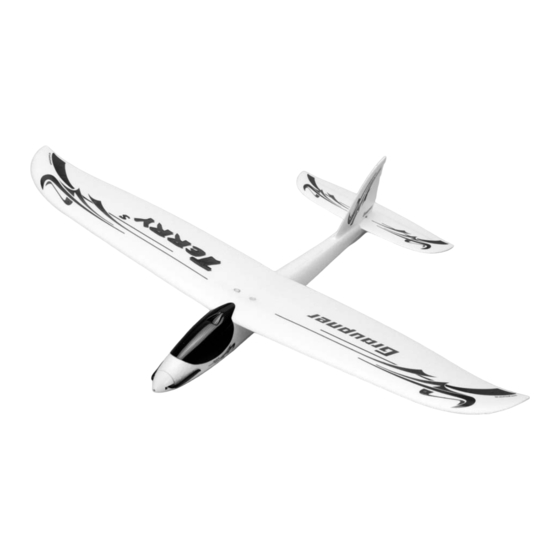
BAUANLEITUNG
TERRY S
Für Elektroantrieb mit 2 LiPo-Zellen
800mAh
Es wird eine Fernsteuerung mit 3 Funktionen benötigt
GRAUPNER GmbH & Co. KG D-73230 KIRCHHEIM/TECK GERMANY
Änderungen vorbehalten! Keine Haftung für Druckfehler!
Id.-Nr. 0058674
10/2007
1
Publicité

Manuels Connexes pour GRAUPNER TERRY S


Sommaire des Matières pour GRAUPNER TERRY S
- Page 1 Best.-Nr. 6297 BAUANLEITUNG TERRY S Für Elektroantrieb mit 2 LiPo-Zellen 800mAh Es wird eine Fernsteuerung mit 3 Funktionen benötigt GRAUPNER GmbH & Co. KG D-73230 KIRCHHEIM/TECK GERMANY Änderungen vorbehalten! Keine Haftung für Druckfehler! Id.-Nr. 0058674 10/2007...
- Page 2 Bedienungsanleitung Ihrer Fernsteueranlage. Es dürfen nur die in dem Bausatz enthaltenen Teile, sowie die ausdrücklich von uns empfohlenen Original-Graupner-Zubehör- und Ersatzteile verwendet werden. Wird eine Komponente der Antriebseinheit geändert, ist ein sicherer Betrieb nicht mehr gewährleistet und es erlischt jeglicher Garantieanspruch.
- Page 3 Das Flugmodell niemals in der Nähe von Hochspannungsleitungen, Industriegeländen, in Wohngebieten, öffentlichen Straßen, Schulhöfen oder Spielplätzen usw. fliegen lassen. Überprüfung vor dem Start Vor jedem Einsatz korrekte Funktion überprüfen. Dazu den Sender einschalten, ebenso den Empfänger. Senderantenne ausziehen, kontrollieren, ob alle Ruder in Neutrallage stehen, einwandfrei funktionieren und seitenrichtig ausschlagen.
- Page 4 Bedienung und Methoden bei Installation, Betrieb, Verwendung und Wartung der Fernsteuerungsanlagen können von der Firma Graupner nicht überwacht werden. Daher übernimmt die Firma Graupner keinerlei Haftung für Verluste, Schäden oder Kosten, die sich aus der fehlerhaften Verwendung und Betrieb ergeben oder in irgendeiner Weise damit zusammenhängen.
- Page 5 Erforderliche Werkzeuge und Klebstoffe Balsamesser Best.-Nr. 980 Schraubendreher Best.-Nr. 810 Seitenschneider Mini-Flachzange Papierschere Sekundenkleber Best.-Nr. 5821 Aktivator für Sekundenkleber Best.-Nr. 953.150 Bauanleitung Bitte lesen Sie vor Baubeginn die Bauanleitung durch, sodass Sie einen Überblick über den Ablauf des Zusammenbaus erhalten. Legen Sie sich die jeweils notwendigen Bauteile, Werkzeuge und Klebstoffe für eine Baustufe bereit .
- Page 6 An der Rumpfvorderseite den fertigungsbedingten Steg für die Motorzuleitungskabel des SPEED 400 PLUS Antriebes entfernen. Für die Durchführung der Servokabel am Rumpfboden einen 10x6 mm großen Durchbruch ausschneiden. Den Durchbruch mittels Kiefernleiste (2) durchstoßen.
- Page 7 Die Rumpfverstärkung (2) exakt mittig in den Rumpf (1) einkleben und andrücken. Darauf achten, dass der Rumpf hierbei nicht durchgebogen wird. Die Spezialmutter (3) mit reichlich Klebstoff aufkleben, dann das auf 440 mm mit dem Balsamesser abgetrennte Bowdenzugaußenrohr HR ( einkleben und mit dem Schraubendreher andrücken.
- Page 8 Das vorbereitete Seitenleitwerk nun probeweise in den Rumpf einschieben, falls zwischen Rumpf und Seitenleitwerk ein Spalt sichtbar ist, den Rumpf an der Oberseite zusammendrücken. Das Seitenleitwerk nun einkleben. Achtung, hierfür keinesfalls Aktivator verwenden. Den Sekundenklebstoff auf die Kiefernleiste (2) und die Rumpfinnenwände auftragen und das Seitenleitwerk zügig einschieben.
- Page 9 Die Inserts (13) einkleben, dazu Schraube (14) eindrehen, damit das Insert jeweils vollständig eingedrückt werden kann. Den SPEED Plus-Antrieb von vorne in den Rumpf bis auf Anschlag einschieben und an der Vorderkante mit Klebstoff sichern. Zur Kontrolle die Klappluftschraube probeweise aufschieben. Luftschraube jedoch erst nach einem Probelauf des Motors festschrauben.
- Page 10 Klettband (20) ausschneiden und aufkleben. Klettband (21) später als Gegenstück auf die Tragfläche (15) kleben. Die Tragfläche Das CFK-Rohr (17) einkleben. Die Buchsen (16) von oben einkleben, Achtung, zügig eindrücken und keinesfalls Aktivator verwenden. Die Installation der RC-Anlage Die Original-Servohebel von den Servos abschrauben, die Servos per Servotester oder RC-Anlage in Mittelstellung bringen, dann die gekürzten Servohebel (24) aufsetzen.
- Page 11 Die Ruderzüge(7) und (8) einschieben , die Servohebel (24) einhängen und aufschrauben. Die Bowdenzugaußenrohre (5) und (6) seitlich an die Verstärkung (2) kleben. Bei neutral eingestelltem Höhenruderservo den Höhenruderzug passend abwinkeln. Seitenruderzug nach selben Prinzip abwinkeln Seitenschneider abtrennen Die Servos sind bereits im Rumpf installiert, das Seitenruderservo in Buchse 1, das Höhenruderservo in Buchse 2 und den SPEED PLUS Antrieb in Buchse 3 des Empfängers einstecken.
- Page 12 Seitenruder zu lange oder zu stark betätigt kommt das Modell in einen Spiralsturz. Die Landung exakt gegen die Windrichtung mit abgeschaltetem Motor durchführen. Vor dem Aufsetzen die Fluggeschwindigkeit des Modells durch dosierte Höhenruderausschläge reduzieren. Die Landung immer gegen die Windrichtung ausführen. Graupner Modellbau wünscht schöne Flüge mit dem Flugmodell >TERRY S<...
- Page 13 Stückliste TERRY S Teil- Benennung Anzahl Werkstoff Abmessung in mm Rumpf SOLIDPOR Fertigteil Rumpfverstärkung Kiefer 450x6x6 Spezialmutter Stahl Fertigteil M4 Seitenleitwerk SOLIDPOR Fertigteil Bowdenzugaußenrohr SR Polyamid Ø 1,9/0,9x380 Bowdenzugaußenrohr HR Polyamid Ø 1,9/0,9x440 Seitenruderzug Stahl Ø 0,8x435 Höhenruderzug Stahl Ø 0,8x515...
- Page 14 Be sure to use only those parts included in the kit, together with other genuine Graupner accessories and replacement parts as recommended expressly by us. Even if you change a single component you can no longer be sure that the system will work reliably, and such changes also invalidate your guarantee.
- Page 15 We suggest that you ask an experienced model flyer for help, or join a model club or flight training school. Your local model shop and the specialist magazines are excellent sources of information. If at all possible, it is always best to join a club and fly at the approved model flying site.
- Page 16 part of your body. For example, a propeller spinning at high speed can easily cut your finger badly. Keep well clear of the rotational plane of the propeller. You never know when some part may come loose and fly off at high speed, hitting you or anybody else in the vicinity;...
- Page 17 Introduction The Terry S is a mini hot-line model with a performance to delight any model flyer. The aeroplane is very highly pre-fabricated, but nevertheless the procedures described in these instructions must be carried out with the greatest care, as this is the only way to ensure that the model flies successfully and safely.
- Page 18 Essential tools and adhesives Balsa knife Order No. 980 Screwdriver Order No. 810 Side-cutters Mini flat-nose pliers Paper scissors Cyano-acrylate glue Order No. 5821 Cyano activator Order No. 953.150 Building instructions Please read right through these building instructions before you start construction, so that you gain a general understanding of the sequence of events.
- Page 19 Trial-fit the spruce strip, and ensure that it makes good contact with the underside of the fuselage over its full length. This is important, as it will be impossible to insert the fin (4) completely if the strip is fitted incorrectly. The production process leaves an unwanted piece of foam at the nose of the fuselage;...
- Page 20 Glue the fuselage reinforcement (2) in the fuselage (1), taking care to keep it exactly central, and push it firmly into place. Check that the spruce strip does not push the fuselage out of shape. Install the captive nut (3) using plenty of adhesive. Cut the elevator snake outer sleeve (6) to a length of 440 mm and glue it in place, pressing it into position with a screwdriver.
- Page 21 When the adhesive has set hard, glue the rudder snake outer (5) to the underside of the fin towards the leading edge. Ensure that it ends flush with the fin; it must not foul the fuselage reinforcement (2), otherwise it will be impossible to install the fin (4) in the correct position.
- Page 22 Glue the aluminium sleeve (11) and the elevator horn (9) in place. Caution: do not use activator when gluing the sleeve. The tailplane can now be attached to the fuselage using the retaining screw (12); you will need to deflect the rudder to one side to reach the screw.
- Page 23 Place the canopy (18) on the fuselage and secure it by fitting the retaining screw (19) through the slot. Cut the Velcro (hook-and-loop) tape (20) to size and stick it in the position shown. Apply the mating piece of Velcro tape (21) to the wing (15). The wing Glue the carbon fibre tube (17) in the wing as shown.
- Page 24 Installing the RC system Undo the servo output screws and prise off the original output arms. Set the servos to centre from the transmitter (or use a servo tester). Cut down the output arms (24) as shown and fit them on the servos. Press the servos into their recesses, and apply a drop of cyano to the mounting lugs to secure them.
- Page 25 Repeat the procedure with the rudder pushrod. Cut off the excess rod material using a pair of side-cutters. The servos are already installed in the fuselage. Connect the rudder servo to socket 1 of the receiver, the elevator servo to socket 2, and the SPEED PLUS motor unit to socket 3.
- Page 26 (motor stopped), heading exactly into wind. Reduce the model’s airspeed just before touch-down by progressively applying up-elevator. Always land straight into any wind. All of us at Graupner Modellbau hope you have many fine flights with your new > TERRY S <.
- Page 27 Parts List - TERRY S Part Description No. off Material Dimensions in mm Fuselage SOLIDPOR Ready made Fuselage reinforcement Spruce 450 x 6 x 6 Captive nut Steel Ready made, M4 SOLIDPOR Ready made Rudder snake outer sleeve Nylon 1.9 Ø / 0.9 Ø x 380...
- Page 28 R/C et de ses accessoires. Il conviendra d'utiliser exclusivement les éléments fournis dans la boite de construction ainsi que les accessoires d'origine Graupner et les pièces détachées conseillées. Si un seul composant de la propulsion est remplacé, une parfaite sécurité...
- Page 29 et la Presse spécialisée. Le mieux est de faire partie d'un club d'aéromodélisme pour pouvoir voler sur un terrain autorisé. Les colles et les peintures contiennent des solvants qui dans certaines conditions peuvent être nocifs pour la santé. Pour cette raison, observez impérativement le mode d'emploi et les avertissements indiqués par le fabricant correspondant.
- Page 30 vitesse et une forte énergie et vous toucher ou une tierce personne, ce qui peut causer de sérieuses blessures. Veillez aussi à ce qu’aucun objet ne vienne en contact avec une hélice en rotation ! Le blocage de l’hélice par un objet quelconque doit absolument être exclu. Avant chaque utilisation, vérifiez le modèle et toutes les pièces qui y sont rattachées (par ex.
- Page 31 Lorsqu’un article que nous distribuons dans la République Fédérale d’Allemagne acquis par un consommateur (§ 13 BGB) présente un défaut de matière ou de fabrication, nous la Firme Graupner GmbH & Co. KG, Kirchheim Teck, prenons en charge la suppression du défaut de l’article dans les conditions ci après.
- Page 32 Nations Unies. Généralités Le TERRY S est un mini modèle Hotline qui procurera beaucoup de plaisir en vol à chaque modéliste. Ce modèle est largement préfabriqué, les stades de montage décrits à la suite devront cependant être effectués avec un grand soin pour garantir les meilleures performances au modèle.
- Page 33 Ciseaux Colle seconde Réf. N° 5821 Activateur pour colle seconde Réf. N° 953.150 Instructions de montage Veuillez lire ces instructions avant de commencer les assemblages afin d’avoir un aperçu sur leur déroulement. Tenez prêts chaque pièce, outil et colle nécessaires pour un stade d’assemblage.
- Page 34 Retirer la traverse existante à l’avant du fuselage (pour les conditions de fabrication) pour le passage des fils de raccordement au moteur de la propulsion SPEED 400 PLUS Pratiquer une ouverture de 10x6mm dans le fond du fuselage pour le passage du cordon du servo.
- Page 35 Presser et coller le renfort (2) exactement au milieu dans le fuselage. Veiller à ce que cela ne déforme pas le fuselage. Coller l’écrou spécial (3) avec une bonne application de colle, coller ensuite la gaine extérieure de la transmission de profondeur (6) coupée sur une longueur de 440mm avec le couteau à...
- Page 36 Introduire maintenant provisoirement la dérive préparée dans le fuselage. si une fente est visible entre le fuselage et la dérive, presser le fuselage par le dessus contre celle-ci. Coller maintenant la dérive en place. Attention, ne pas utiliser d’activateur pour ce collage ! Appliquer de la colle seconde sur la baguette de pin (2) et sur les parois intérieures du fuselage, puis introduire rapidement la dérive ;...
- Page 37 Coller les inserts (13) ; pour cela, visser les vis (14) afin que les inserts puissent être totalement encastrés. Introduire la propulsion SPEED Plus jusqu’en butée dans l’avant du fuselage et la fixer sur le couple avant avec de la colle. Mettre provisoirement en place l’hélice à pales repliables pour contrôle.
- Page 38 Découper la bande à crampons (20) ; la contre partie (21) sera collée ultérieurement sur l’aile (15). L’aile Coller le tube en fibre de carbone (17). Coller les bagues (16) par le dessus. Attention, les enfoncer rapidement et n’utiliser en aucun cas d’activateur. Installation de l’ensemble R/C Démonter le palonnier original des servos et mettre ces derniers en position neutre avec un testeur de servos ou avec l’ensemble R/C ;...
- Page 39 Introduire les transmissions (7) et (8), collecter les palonniers (24) et les monter sur les servos. Coller les gaines extérieures de transmission (5) et (6) latéralement sur le renfort (2). Contre couder en correspondance la transmission de profondeur avec le servo réglé au neutre.
- Page 40 Effectuez les atterrissages toujours contre la direction du vent. Graupner Modélisme vous souhaite de beaux vols avec le modèle TERRY S !
- Page 41 Liste des pièces TERRY S Désignation Qté Matériel Dimensions en mm. N° r. Fuselage SOLIDPOR Pièce finie Renfort de fuselage 450x6x6 Ecrou spécial Acier Pièce finie M4 Dérive SOLIDPOR Pièce finie Gaine extérieure direction Polyamide Ø 1,9/0,9x380 Gaine extérieure profondeur Polyamide Ø...