Fronius TransPocket 2500 Instructions De Service
Masquer les pouces
Voir aussi pour TransPocket 2500:
- Instructions de service (52 pages) ,
- Instructions de service (52 pages)
Table des Matières
Publicité
Les langues disponibles
Les langues disponibles
Liens rapides
Publicité
Chapitres
Table des Matières

Manuels Connexes pour Fronius TransPocket 2500


Sommaire des Matières pour Fronius TransPocket 2500
- Page 1 Bedienungsanleitung Ersatzteilliste E-Hand Stromquelle Operating Instructions Spare Parts List MMA power source TransPocket 2500 Instructions de service TransPocket 2500 TIG Liste de pièces de rechange Source de courant électrique- manuel 42,0410,1267 012006...
- Page 3 Einleitung Wir danken Ihnen für Ihr entgegengebrachtes Vertrauen und gratulieren Ihnen zu Ihrem technisch hochwertigen Fronius Produkt. Die vorliegende Anleitung hilft Ihnen, sich mit diesem vertraut zu machen. Indem Sie die Anleitung sorgfältig lesen, lernen Sie die vielfältigen Möglichkeiten Ihres Fronius-Produktes kennen. Nur so können Sie seine Vorteile bestmöglich nutzen.
-
Page 5: Sicherheitsvorschriften
Sicherheitsvorschriften GEFAHR! „GEFAHR!“ Bezeichnet eine unmittelbar drohende Gefahr. Wenn sie nicht gemieden wird, sind Tod oder schwerste Verletzungen die Folge. WARNUNG! „WARNUNG!“ Bezeichnet eine möglicherweise gefährliche Situation. Wenn sie nicht gemieden wird, können Tod und schwerste Verletzungen die Folge sein. VORSICHT! „VORSICHT!“... - Page 6 Allgemeines Störungen, die die Sicherheit beeinträchtigen können, vor dem Einschalten (Fortsetzung) des Gerätes beseitigen. Es geht um Ihre Sicherheit! Bestimmungsge- Das Gerät ist ausschließlich für Arbeiten im Sinne der bestimmungsgemä- mäße Verwen- ßen Verwendung zu benutzen. dung Das Gerät ist ausschließlich für die am Leistungsschild angegebenen Schweißverfahren bestimmt.
- Page 7 Verpflichtungen Der Betreiber verpflichtet sich, nur Personen am Gerät arbeiten zu lassen, des Betreibers mit den grundlegenden Vorschriften über Arbeitssicherheit und Unfallver- hütung vertraut und in die Handhabung des Gerätes eingewiesen sind das Kapitel „Sicherheitsvorschriften“ und die Warnhinweise in dieser Bedienungsanleitung gelesen, verstanden und durch ihre Unterschrift bestätigt haben entsprechend den Anforderungen an die Arbeitsergebnisse ausgebildet...
- Page 8 Selbst- und Zur Schutzbekleidung zählt unter anderem: Personenschutz (Fortsetzung) Augen und Gesicht durch Schutzschild mit vorschriftsgemäßem Filter- Einsatz vor UV-Strahlen, Hitze und Funkenflug schützen. Hinter dem Schutzschild eine vorschriftsgemäße Schutzbrille mit Seiten- schutz tragen. Festes, auch bei Nässe isolierendes Schuhwerk tragen Hände durch geeignete Handschuhe schützen (elektrisch isolierend, Hitzeschutz).
- Page 9 Gefahr durch Funkenflug kann Brände und Explosionen auslösen. Funkenflug Niemals in der Nähe brennbarer Materialien schweißen. Brennbare Materialien müssen mindestens 11 Meter (35 ft.) vom Lichtbogen entfernt sein oder mit einer geprüften Abdeckung zugedeckt werden. Geeigneten, geprüften Feuerlöscher bereithalten. Funken und heiße Metallteile können auch durch kleine Ritzen und Öffnun- gen in umliegende Bereiche gelangen.
- Page 10 Gefahren durch Netz- und Gerätezuleitung regelmäßig von einer Elektro-Fachkraft auf Netz- und Funktionstüchtigkeit des Schutzleiters überprüfen lassen. Schweißstrom (Fortsetzung) Das Gerät nur an einem Netz mit Schutzleiter und einer Steckdose mit Schutzleiter-Kontakt betreiben. Wird das Gerät an einem Netz ohne Schutzleiter und an einer Steckdose ohne Schutzleiterkontakt betrieben, gilt dies als grob fahrlässig.
- Page 11 EMV- und EMF- Es liegt im Verantwortungsbereich des Betreibers, dafür Sorge zu tragen, Maßnahmen dass keine elektromagnetischen Störungen an elektrischen und elektroni- schen Einrichtungen auftreten Werden elektromagnetische Störungen festgestellt, ist der Betreiber ver- pflichtet, Maßnahmen für die Störungsbehebung zu ergreifen. Mögliche Probleme und Störfestigkeit von Einrichtungen in der Umgebung gemäß...
- Page 12 Besondere Abdeckungen und Seitenteile dürfen nur für die Dauer von Wartungs- und Reparaturar- Gefahrenstellen beiten geöffnet / entfernt werden. (Fortsetzung) Während des Betriebes Sicherstellen, dass alle Abdeckungen geschlossen und sämtliche Seitenteile ord- nungsgemäß montiert sind. Alle Abdeckungen und Seitenteile geschlossen halten. Austritt des Schweißdrahtes aus dem Schweißbrenner bedeutet ein hohes Verletzungsrisiko (Durchstechen der Hand, Verletzung von Gesicht und Augen, ...).
- Page 13 Gefahr durch Schutzgasflaschen enthalten unter Druck stehendes Gas und können bei Schutzgasfla- Beschädigung explodieren. Da Schutzgasflaschen Bestandteil der Schweiß- schen ausrüstung sind, müssen sie sehr vorsichtig behandelt werden. Schutzgasflaschen mit verdichtetem Gas vor zu großer Hitze, mechanischen Schlägen, Schlacke, offenen Flammen, Funken und Lichtbögen schützen. Die Schutzgasflaschen senkrecht montieren und gemäß...
- Page 14 Sicherheitsmaß- Vor jedem Transport des Gerätes, das Kühlmittel vollständig ablassen, sowie nahmen am folgende Komponenten demontieren: Aufstellort und Drahtvorschub beim Transport Drahtspule (Fortsetzung) Schutzgasflasche Vor der Inbetriebnahme, nach dem Transport, unbedingt eine Sichtprüfung des Gerätes auf Beschädigungen vornehmen. Allfällige Beschädigungen vor Inbetriebnahme von geschultem Servicepersonal instandsetzen lassen.
- Page 15 Bei Bestellung genaue Benennung und Sach-Nummer laut Ersatzteilliste, sowie Serien- Wartung und Instandsetzung nummer Ihres Gerätes angeben. (Fortsetzung) Sicherheitstech- Der Betreiber ist verpflichtet, mindestens alle 12 Monate eine sicherheits- nische Überprü- technische Überprüfung am Gerät durchführen zu lassen. fung Innerhalb desselben Intervalles von 12 Monaten empfiehlt der Hersteller eine Kalibrierung von Stromquellen.
- Page 16 Urheberrecht Das Urheberrecht an dieser Bedienungsanleitung verbleibt beim Hersteller. Text und Abbildungen entsprechen dem technischen Stand bei Drucklegung. Änderungen vorbehalten. Der Inhalt der Bedienungsanleitung begründet keinerlei Ansprüche seitens des Käufers. Für Verbesserungsvorschläge und Hinweise auf Fehler in der Bedienungsanleitung sind wir dankbar. ud_fr_st_sv_00466 012005...
-
Page 17: Table Des Matières
Inhaltsverzeichnis Allgemeines ..............................3 Prinzip ..............................3 Gerätekonzept ............................3 Einsatzgebiete ............................3 Bedienelemente und Anschlüsse ........................4 Sicherheit ..............................4 Anschlüsse ............................... 4 Bedienelemente ............................5 Vor der Inbetriebnahme ..........................6 Sicherheit ..............................6 Bestimmungsgemässe Verwendung ......................6 Aufstellbestimmungen ..........................6 Netzanschluss ............................ - Page 18 Technische Daten ............................22 Sicherheit ............................... 22 TP 2500, TP 2500 TIG ........................... 22 Ersatzteillisten Schaltpläne Fronius Worldwide...
-
Page 19: Allgemeines
Allgemeines Prinzip Die Stromquelle TP 2500 ist ein weiteres Highlight der neuen Generation von Schweißinvertern. Mit Hilfe der Hochlei- stungselektronik wurde ein einzigartiges Schweißgerät mit hoher Leistung und geringem Gewicht geschaffen. Die Stromquelle arbeitet nach dem Prinzip eines Resonanzinverters und bietet daher eine Reihe von Vorteilen: Intelligente Regelung für stabilen Lichtbogen und ideale Kennlinie... -
Page 20: Bedienelemente Und Anschlüsse
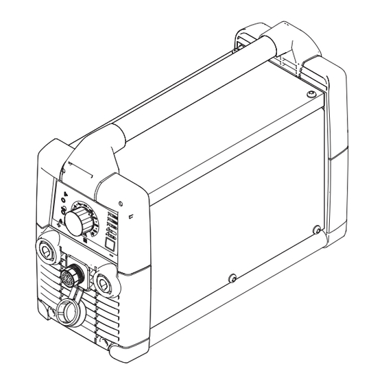
Bedienelemente und Anschlüsse Sicherheit WARNUNG! Fehlbedienung kann schwerwiegende Personen- und Sachschä- den verursachen. Beschriebene Funktionen erst anwenden, wenn folgende Dokumente vollständig gelesen und verstanden wurden: diese Bedienungsanleitung sämtliche Bedienungsanleitungen der Systemkomponenten, insbesondere Sicherheitsvorschriften Anschlüsse Abb.2 Elemente und Anschlüsse an der Vorder- und Rückseite (1) Netzschalter (2) Anschlussbuchse Schutzgas (nur bei TP 2500 TIG) ... -
Page 21: Bedienelemente
Bedienelemente (10) Abb.3 Bedienelemente und Anzeigen am Bedienpanel (7) Taste Verfahren ... zur Anwahl des Schweißverfahrens Stabelektroden-Schweißen mit rutiler Elektrode Stabelektroden-Schweißen mit basischer Elektrode Stabelektroden-Schweißen mit CEL-Elektrode WIG-Schweißen WIG-Impulslichtbogenschweißen (nur bei TP 2500 TIG) Wichtig! Auch nach dem Ziehen des Netzsteckers bleibt das angewählte Schweißver- fahren gespeichert. -
Page 22: Vor Der Inbetriebnahme
Vor der Inbetriebnahme Sicherheit WARNUNG! Fehlbedienung kann schwerwiegende Personen- und Sachschä- den verursachen. Beschriebene Funktionen erst anwenden, wenn folgende Dokumente vollständig gelesen und verstanden wurden: diese Bedienungsanleitung sämtliche Bedienungsanleitungen der Systemkomponenten, insbesondere Sicherheitsvorschriften Die Stromquelle ist ausschließlich zum Stabelektroden-und WIG-Schweißen bestimmt. Bestimmungsge- Eine andere oder darüber hinausgehende Benutzung gilt als nicht bestimmungsgemäß. -
Page 23: Stabelektroden-Schweißen
Stabelektroden-Schweißen Sicherheit WARNUNG! Fehlbedienung kann schwerwiegende Personen- und Sachschä- den verursachen. Beschriebene Funktionen erst anwenden, wenn folgende Dokumente vollständig gelesen und verstanden wurden: diese Bedienungsanleitung sämtliche Bedienungsanleitungen der Systemkomponenten, insbesondere Sicherheitsvorschriften WARNUNG! Ein Elektroschock kann tödlich sein. Ist das Gerät während der Installation am Netz angesteckt, besteht die Gefahr schwerwiegender Perso- nen und Sachschäden. -
Page 24: Funktion Hot-Start (Aktiv Bei Verfahren Rutil Und Cel)
Vorteile: Funktion Hot- I (A) Verbesserung der Zündeigenschaften, Start (aktiv bei auch bei Elektroden mit schlechten Verfahren Rutil 120A Zündeigenschaften und Cel) Besseres Aufschmelzen des Grund- werkstoffes in der Startphase, da- durch weniger Kaltstellen Weitgehende Vermeidung von Schlacken-Einschlüssen 1,5 s Abb.4 Beispiel für die Funktion "Hot-Start"... -
Page 25: Wig-Schweißen
WIG-Schweißen Sicherheit WARNUNG! Fehlbedienung kann schwerwiegende Personen- und Sachschä- den verursachen. Beschriebene Funktionen erst anwenden, wenn folgende Dokumente vollständig gelesen und verstanden wurden: diese Bedienungsanleitung sämtliche Bedienungsanleitungen der Systemkomponenten, insbesondere Sicherheitsvorschriften WARNUNG! Ein Elektroschock kann tödlich sein. Ist das Gerät während der Installation am Netz angesteckt, besteht die Gefahr schwerwiegender Perso- nen und Sachschäden. -
Page 26: Verfahren Anwählen
Schutzgasmenge VORSICHT! Gefahr von Personen- und Sachschäden durch Elektroschock. einstellen Sobald der Netzschalter in Stellung „I“ geschaltet ist, ist die Wolframelektrode des Schweißbrenners spannungsführend. Darauf achten, dass die Wolfram- elektrode keine Personen oder elektrisch leitenden oder geerdeten Teile berührt (z.B. Gehäuse, etc.) Bei Verwendung eines Gasschieberbrenners: Netzschalter in Stellung "I"... -
Page 27: Funktion Tig-Comfort-Stop
Schweißstrom Gasdüse aufsetzen Zünden durch Gasdüse anheben einstellen, Licht- Werkstückberührung Lichtbogen zündet bogen zünden (Fortsetzung) Abb.6 Brennerstellungen beim Schweißstart Funktion TIG- Die Funktion "TIG-Comfort-Stop" (TCS) steht nur bei der Stromquelle TP 2500 TIG zur Comfort-Stop Verfügung. Standardmäßig ist die Funktion TIG-Comfort-Stop deaktiviert. Die Aktivierung und Einstellung der Funktion TIG-Comfort-Stop wird im Kapitel "Das Setup-Menü"... - Page 28 Funktion TIG- Downslope: Comfort-Stop Der Downslope ist abhängig vom gewählten Schweißstrom und kann nicht eingestellt (Fortsetzung) werden. Der Dauer des Downslopes zwischen den nachfolgenden angegebenen Werten ist linear hochzurechnen. Downslope bei niedrigem Schweißstrom (10 A): 0,1 Sekunden Downslope bei maximalem Schweißstrom (250 A): 2,5 Sekunden Gasnachströmzeit: Die Gasnachströmzeit ist abhängig vom gewählten Schweißstrom und kann nicht...
-
Page 29: Das Setup-Menü
Das Setup-Menü Einstellmöglich- Verfahren einstellbarer Parameter Werkseinstellung keiten Dynamik Stufe 2 Dynamik Stufe 2 Cel-Kennlinie und Dynamik Stufe 2 TIG-Comfort-Stop Stufe 0 Pulsfrequenz (nur TP 2500 TIG) Stufe 1 Funktionsprinzip Die Parameter sind in 4 Stufen (TP 2500) oder in 5 Stufen (TP 2500 TIG) einstellbar. Die Anzahl der leuchtenden Anzeigen entspricht der eingestellten Stufe. -
Page 30: Parameter Cel-Kennlinie
Parameter Dyna- Der Parameter Dynamik dient zur Beein- U (V) flussung der Kurzschluss-Stromstärke im Moment des Tropfen-Überganges. Bei Tendenz zum Festkleben der Stab- elektrode, den Parameter Dynamik auf eine höhere Stufe einstellen. Stufe 0 ergibt einen besonders weichen eingestellter und spritzerarmen Lichtbogen. Schweißstrom I (A) Stufe 4 oder 5 ergibt einen besonders... -
Page 31: Parameter Pulsfrequenz
Parameter Puls- Der Parameter Frequenz steht nur bei der Stromquelle TP 2500 TIG zur Verfügung und frequenz dient zur Einstellung der Frequenz des Impulslichtbogens. Für die Schweißeigenschaften beim WIG-Impulslichtbogen-Schweißen ist die Frequenz des Impulslichtbogens ein wesentliches Kriterium. Stufe Pulsfrequenz 60 Hz 10 Hz 4 Hz 2 Hz... -
Page 32: Voltage Reduction Device (Vrd)
Voltage Reduction Device (VRD) Allgemeines Voltage Reduction Device (VRD) ist eine optionale Sicherheitseinrichtung zur Span- nungsreduzierung. VRD verhindert soweit wie möglich Ausgangsspannungen an den Strombuchsen, die eine Gefährdung von Personen darstellen können. Sicherheitsprin- Schweißkreiswiderstand ist größer als der minimale Körperwiderstand (größer oder gleich 200 Ohm): VRD ist aktiv Leerlaufspannung ist auf 12 V be-... -
Page 33: Fehlerdiagnose Und -Behebung
Fehlerdiagnose und -behebung Sicherheit WARNUNG! Ein Elektroschock kann tödlich sein. Vor Öffnen des Gerätes Netzschalter in Stellung „O“ schalten Gerät vom Netz trennen ein verständliches Warnschild gegen Wiedereinschalten anbringen mit Hilfe eines geeigneten Messgerätes sicherstellen, dass elektrisch geladene Bauteile (z.B. Kondensatoren) entladen sind VORSICHT! Unzureichende Schutzleiter-Verbindung kann schwerwiegende Personen- und Sachschäden verursachen. - Page 34 Fehlerdiagnose Schlechte Zündeigenschaften beim Stabelektrodenschweißen (Fortsetzung) Ursache: falsches Verfahren angewählt Behebung: Verfahren "Stabelektroden-Schweißen" oder "Stabelektroden-Schweißen mit CEL-Elektrode" anwählen Lichtbogen reißt während des Schweißvorganges fallweise ab Ursache: Bei angewähltem Verfahren WIG-Schweißen, Parameter TIG-Comfort-Stop auf zu niedrigem Wert eingestellt Behebung: Im Setup-Menü den Parameter TIG-Comfort-Stop auf einen höheren Wert einstellen Ursache: Zu hohe Brennspannung der Elektrode (z.B.
-
Page 35: Error Anzeigen
Error Anzeigen Leerlauf Error nebenstehende Anzeigen leuchten, Anzeige VRD blinkt rot Ursache: Ausgangsspannung ist größer 110V Behebung: Gerät ausschalten und anschließend wieder einschalten; Fehler tritt gehäuft auf - Gerät zum Service Netz-Unterspannung bzw. Netz-Überspannung nebenstehende Anzeigen leuchten, Anzeige VRD blinkt rot Ursache: Netzspannung hat den Toleranzbereich unter- oder über- schritten... - Page 36 Error Anzeigen Primärstrom Error (Fortsetzung) nebenstehende Anzeigen leuchten, Anzeige VRD blinkt rot Ursache: Interner Error Behebung: Gerät ausschalten und anschließend wieder einschalten; Fehler tritt gehäuft auf - Gerät zum Service...
-
Page 37: Pflege, Wartung Und Entsorgung
Pflege, Wartung und Entsorgung Die Stromquelle benötigt unter normalen Betriebsbedingungen nur ein Minimum an Allgemeines Pflege und Wartung. Das Beachten einiger Punkte ist jedoch unerlässlich, um die Schweißanlage über Jahre hinweg einsatzbereit zu halten. WARNUNG! Ein Elektroschock kann tödlich sein. Vor Öffnen des Gerätes Netzschalter in Stellung „O“... -
Page 38: Technische Daten
Technische Daten Sicherheit HINWEIS! Nicht ausreichend dimensionierte Elektroinstallation kann zu schwer- wiegenden Sachschäden führen. Die Netzzuleitung sowie deren Absicherung sind entsprechend auszulegen. Es gelten die Technischen Daten auf dem Leistungsschild. TP 2500, TP 2500 Netzspannung 380-460 V Netzspannungstoleranz ± 10 % Netzfrequenz 50 / 60 Hz Netzabsicherung... - Page 39 Read the manual carefully and you will soon be familiar with all the many great features of your new Fronius product. This really is the best way to get the most out of all the advantages that your machine has to offer.
-
Page 41: Safety Rules
Safety rules DANGER! “DANGER!” indicates an imminently hazardous situation which, if not avoided, will result in death or serious injury. This signal word is to be limited to the most extreme situations. This signal word is not used for property damage hazards unless personal injury risk appropriate to this level is also involved. - Page 42 General remarks must not be removed (continued) must not be covered, pasted or painted over For information about where the safety instructions and danger warnings are located on the machine, please see the section of your machine’s instruction manual headed “General remarks”. Any malfunctions which might impair machine safety must be eliminated immediately - meaning before the equipment is next switched on.
- Page 43 Obligations of The owner/operator undertakes to ensure that the only persons allowed to owner/operator work with the machine are persons who are familiar with the basic regulations on workplace safety and accident prevention and who have been instructed in how to operate the machine have read and understood the sections on “safety rules”...
- Page 44 Protection for “Protective clothing” also includes: yourself and protecting your eyes and face from UV rays, heat and flying sparks with other persons an appropriate safety shield containing appropriate regulation filter glass (continued) wearing a pair of appropriate regulation goggles (with sideguards) behind the safety shield wearing stout footwear that will also insulate even in wet conditions protecting your hands by wearing appropriate gloves (electrically insula-...
- Page 45 Hazards from Flying sparks can cause fires and explosions! flying sparks Never perform welding anywhere near combustible materials. Combustible materials must be at least 11 meters (35 feet) away from the arc, or else must be covered over with approved coverings. Have a suitable, approved fire extinguisher at the ready.
- Page 46 Hazards from If the machine is run on a mains network without a PE conductor and mains and weld- plugged into a power outlet socket without a protective-conductor contact, ing current this counts as gross negligence and the manufacturer shall not be liable for (continued) any resulting damage.
- Page 47 EMC and EMI It is the responsibility of the owner/operator to ensure that no electromagnetic Precautions interference is caused to electrical and electronic equipment. If electromagnetic interference is found to be occurring, the owner/operator is obliged to take all necessary measures to prevent this interference. Examine and evaluate any possible electromagnetic problems that may occur on equipment in the vicinity, and the degree of immunity of this equipment, in accordance with national and international regulations:...
- Page 48 Particular danger While the machine is in use: spots ensure that all the covers are closed and that all the sideguards are (continued) properly mounted ..and that all covers and sideguards are kept closed. When the welding wire emerges from the torch, there is a high risk of injury (the wire may pierce the welder’s hand, injure his face and eyes ...).
- Page 49 Danger from Shielding-gas cylinders contain pressurized gas and may explode if they are shielding-gas damaged. As shielding-gas cylinders are an integral part of the overall cylinders welding outfit, they also have to be treated with great care. Protect shielding-gas cylinders containing compressed gas from excessive heat, mechanical impact, slag, naked flames, sparks and arcs.
- Page 50 Safety precauti- Before transportation, completely drain any coolant and dismantle the follo- ons at the instal- wing components: lation site and Wire feed when being Wire wound coil transported Gas bottle (continued) Before commissioning and after transportation, a visual check for damage must be carried out.
- Page 51 Preventive and When ordering spare parts, please state the exact designation and the corrective main- relevant part number, as given in the spare parts list. Please also quote the tenance serial number of your machine. (continued) Safety inspection The owner/operator is obliged to have a safety inspection performed on the machine at least once every 12 months.
- Page 52 Copyright Copyright to this instruction manual remains the property of the manufacturer. The text and illustrations are all technically correct at the time of going to print. The right to effect modifications is reserved. The contents of the in- struction manual shall not provide the basis for any claims whatever on the part of the purchaser.
- Page 53 Inhaltsverzeichnis General remarks ............................3 Basic system principle ..........................3 Machine concept ............................3 Application areas ............................3 Controls and connections ..........................4 Safety ............................... 4 Connections ............................. 4 Controls ..............................5 Before commissioning ........................... 6 Safety ............................... 6 Utilisation for intended purpose only ......................6 Setup regulations .............................
- Page 54 Technical data ............................. 22 Safety ..............................22 TP 2500, TP 2500 TIG ........................... 22 Spare parts lists Circuit diagrams Fronius Worldwide...
-
Page 55: General Remarks
General remarks Basic system The TP 2500 power source is a further principle highlight of the new generation of welding inverters. Using powerful electronics, a unique high-capability, lightweight welding machine has been created. The power source works on resonance inverter principles and therefore offers a number of advantages: Intelligent control for stable arc and ideal characteristic... -
Page 56: Controls And Connections
Controls and connections Safety WARNING! Operating the equipment incorrectly can cause serious injury and damage. You should not use the functions described until you have thoroughly read and understood the following documents: these operating instructions all the operating instructions for the system components, especially the safety regulations Connections Fig. -
Page 57: Controls
Controls (10) Fig.3 Controls and indicators on the control panel (7) Process button ... for selecting the welding process Rod electrode welding with rutile electrode Rod electrode welding with basic electrode Rod electrode welding with CEL electrode TIG welding TIG pulsed arc welding (TP 2500 TIG only) Important! The selected welding process remains stored even after the mains plug is disconnected. -
Page 58: Before Commissioning
Before commissioning Safety WARNING! Operating the equipment incorrectly can cause serious injury and damage. You should not use the functions described until you have thoroughly read and understood the following documents: these operating instructions all the operating instructions for the system components, especially the safety regulations The power source may only be used for rod electrode (MMA) and TIG welding. -
Page 59: Rod Electrode (Mma) Welding
Rod electrode (MMA) welding Safety WARNING! Operating the equipment incorrectly can cause serious injury and damage. You should not use the functions described until you have thoroughly read and understood the following documents: these operating instructions all the operating instructions for the system components, especially the safety regulations WARNING! An electric shock can be fatal. - Page 60 Advantages: Hot-Start Func- I (A) Improved ignition, even when using tion (used with electrodes with poor ignition proper- rutile and Cel 120A ties processes) Better fusion of the base metal in the start-up phase, meaning fewer cold- shut defects Largely prevents slag inclusions 1.5 s Fig.4 Example of „Hot-Start“...
-
Page 61: Tig Welding
TIG welding Safety WARNING! Operating the equipment incorrectly can cause serious injury and damage. You should not use the functions described until you have thoroughly read and understood the following documents: these operating instructions all the operating instructions for the system components, especially the safety regulations WARNING! An electric shock can be fatal. -
Page 62: Adjusting Welding Current, Igniting The Arc
Setting the CAUTION! Risk of injury and damage from electric shock. As soon as the shielding gas mains switch is in the “I” position, the tungsten electrode of the welding torch flow rate is LIVE. Make sure that the tungsten electrode does not touch any persons or electrically conducting or earthed parts (e.g. -
Page 63: Adjusting Welding Current, Igniting The Arc
Adjusting wel- Placing the gas nozzle Arc ignites when electrode is Raise gas nozzle ding current, touched down on workpiece Arc ignites igniting the arc (continued) Fig.6 Torch settings when welding begins TIG-Comfort- The „TIG-Comfort-Stop“ function (TCS) is only available with the TP 2500 TIG power Stop function source. - Page 64 TIG-Comfort- Downslope: Stop function The downslope depends on the welding current selected and cannot be adjusted. The (continued) duration of the downslope between the following values must be extrapolated. Downslope at low welding current (10 A): 0.1 seconds Downslope at maximum welding current (250 A): 2.5 seconds Gas post-flow time: The gas post-flow time depends on the welding current selected and cannot be adjusted.
-
Page 65: The Setup Menu
The Setup menu Setting options Process Settable parameters Factory setting Dynamic Level 2 Dynamic Level 2 Cel characteristic and arc-force dynamic Level 2 TIG Comfort stop Level 0 Pulsing frequency (TP 2500 TIG only) Level 1 Functional prin- The parameters can be set at 4 levels (TP 2500) or 5 levels (TP 2500 TIG). The number ciple of indicators lit corresponds to the level reached. -
Page 66: Arc-Force Dynamic Parameter
Arc-force dyna- The purpose of the arc-force dynamic mic parameter U (V) parameter is to influence the short-circuit current at the moment of droplet transfer. If the rod electrode has a tendency to stick, adjust the arc-force dynamic para- meter to a higher level. Level 0 produces an especially soft and Pre-set low-spatter arc. -
Page 67: Pulsing Frequency Parameter
Pulsing frequen- The frequency parameter is only available on the TP 2500 TIG power source and is for cy parameter setting the frequency of the pulsed arc. The pulsed arc frequency is one of the most important criterion for the TIG pulsed arc welding properties. -
Page 68: Voltage Reduction Device (Vrd)
Voltage Reduction Device (VRD) General remarks Voltage Reduction Device (VRD) is an optional safety device for voltage reduction. As far as possible, VRD prevents output voltages at the current sockets that may pose a danger to persons. Safety principle Welding circuit resistance is greater than the minimum human body resistance (greater than or equal to 200 Ohm): VRD is active... -
Page 69: Troubleshooting
Troubleshooting Safety WARNING! An electric shock can be fatal. Before opening up the machine Move the mains switch to the „O“ position Unplug machine from the mains Put up an easy-to-understand warning sign to stop anybody inadvertently switching it back on again Using a suitable measuring instrument, check to make sure that electri- cally charged components (e.g. -
Page 70: Fault Diagnosis
Fault diagnosis Poor ignition properties during rod electrode (MMA) welding (continued) Cause: Incorrect process selected Remedy: Select „Rod electrode (MMA) welding“ or „Rod electrode (MMA) welding with CEL electrode“ process In some cases arc breaks during welding Cause: TIG-Comfort-Stop parameter value set too low for selected TIG welding process Remedy: Adjust the TIG-Comfort-Stop parameter to a higher value in the set-up... -
Page 71: Error Indicators
Error indicators Idle error Indicators shown on the right light up, VRD indicator flashes red Cause: Output voltage is greater than 110V Remedy: Switch machine off and on again; if error keeps recurring, have machine serviced Mains undervoltage or overvoltage Indicators shown on the right light up, VRD indicator flashes red Cause: The mains voltage is outside the tolerance range... - Page 72 Error indicators Primary current error (continued) Indicators shown on the right light up, VRD indicator flashes red Cause: Internal error Remedy: Switch machine off and on again; if error keeps recurring, have machine serviced...
-
Page 73: Care, Maintenance And Disposal
Care, maintenance and disposal Under normal operating conditions the power source requires only a minimum of care General remarks and maintenance. However, it is vital to observe some important points to ensure the welding machine remains in a usable condition for many years. WARNING! An electric shock can be fatal. -
Page 74: Technical Data
Technical data Safety NOTE! Inadequately dimensioned electrical installations can lead to serious damage. The mains lead and its fuse protection must be rated accordingly. The technical data shown on the rating plate shall apply. TP 2500, TP 2500 Mains voltage 380-460 V Mains voltage tolerance ±... -
Page 75: Cher Lecteur
Introduction Nous vous remercions de votre confiance et vous félicitons d’avoir acheté un produit de qualité supérieure de Fronius. Les instructions suivantes vous aideront à vous familiari- ser avec le produit. En lisant attentivement les instructions de service suivante, vous découvrirez les multiples possibilités de votre produit Fronius. -
Page 77: Consignes De Sécurité
Consignes de sécurité DANGER! «DANGER!» caractérise un péril immédiat. S’y exposer entraîne la mort ou des blessures graves. AVERTISSE- «AVERTISSEMENT» caractérise une situation pouvant s’avérer dangereu- MENT! se. S’y exposer peut entraîner la mort et des blessures graves. ATTENTION! «ATTENTION!» caractérise une situation pouvant s’avérer néfaste. S’y exposer peut entraîner des blessures légères ou minimes ainsi que des dégâts matériels. - Page 78 Généralités Tout dérangement pouvant nuire à la sécurité doit être éliminé avant de (suite) mettre en marche l’appareil. Votre sécurité est en jeu ! Uilisation confor- L’appareil a été conçue exclusivement pour une utilisation de le cadre des travaux prévus. L’appareil est exclusivement conçu pour les procédés de soudage indiqués sur la plaque signalétique.
- Page 79 Obligations de L‘exploitant s‘engage à n‘autoriser l‘utilisation de l’appareil qu‘à des person- l‘exploitant connaissant les prescriptions fondamentales concernant la sécurité du travail et la prévention d‘accidents et familiarisées avec la manipulation de l’appareil ayant lu et compris les avertissements figurant dans ces instructions de service, et l‘ayant confirmé...
- Page 80 Auto-protection Font entre autre partie des vêtements de protection: et protection des personnes Protégez les yeux et la face des rayons ultraviolets , de la chaleur et de (suite) la projection d’étincelles en utilisant un écran de soudeur doté de verres filtrants réglementaires.
- Page 81 Risques pro- La projection d’étincelles peut causer des incendies et des explosions. venant de la projection Ne jamais souder à proximité de matériaux inflammables. d‘étincelles Les matériaux inflammables doivent être éloignés d’au moins 11 mètres (35 pieds) de l’arc lumineux ou recouverts d’une feuille homologuée. Garder des extincteurs appropriés à...
- Page 82 Risques pro- Faire vérifier régulièrement par un électricien professionnel le conducteur de venant du cou- terre de la ligne d‘alimentation secteur et la ligne d‘alimentation de l‘appareil. rant secteur et du courant de N’exploiter l’appareil que sur un réseau muni de conducteur de protection et soudage une prise de courant avec contact de conducteur de protection.
- Page 83 Mesures EMV et Veiller à ce que des pannes électromagnétiques ne surviennent pas sur les installations électriques et électroniques fait partie de la responsabilité de l’exploitant. Quand on constate des pannes électromagnétiques, l’exploitant est tenu de prendre des mesures pour les éliminer. Examiner et évaluer tout problème éventuel et la résistance aux pannes des installations à...
- Page 84 Zones particu- Pendant la marche: lièrement dange- S’assurer que tous les recouvrements soient fermés et l’ensemble des reuses parties latérales correctement montées. (suite) Maintenir fermés tous les recouvrements et parties latérales. La sortie du fil-électrode du brûleur représente un danger élevé de blessures (perforation de la main, blessures du visage et des yeux,...).
- Page 85 Danger par les Les bonbonnes de gaz de protection contiennent du gaz sous pression et bonbonnes de peuvent exploser en cas d’endommagement. Comme les bonbonnes de gaz gaz de protection de protection font partie de l’équipement requis pour le soudage, il convient de les manipuler avec le plus grand soin.
- Page 86 Mesures de Avant de transporter l’appareil, vidanger entièrement le fluide réfrigérant et sécurité sur le démonter les composants suivants: lieu d‘installation Dévidoir de l’appareil et Bobine de fil pendant le trans- Bouteille de gaz protecteur port (suite) Avant la mise la mise en service suivant le transport, effectuer impérative- ment un contrôle visuel de l’appareil, pour voir s’il est endommagé.
- Page 87 Entretien et Pour toute commande, prière d‘indiquer la dénomination et le numéro de réparation référence exacts, comme indiqués sur la liste des pièces de rechange, ainsi (suite) que le numéro de série de l’appareil. Contrôle de Au moins une fois tous les douze mois, l‘exploitant est tenu de faire effectuer sécurité...
- Page 88 Droits d‘auteur Le fabricant est propriétaire des droits d‘auteurs sur ces instructions de service. Le texte et les figures correspondent à l‘état de la technique lors de la mise sous presse. Sous réserve de modification. Le contenu des présentes instructions de service ne fondent aucun recours de la part de l‘acheteur. Nous sommes reconnaissants pour toute proposition d‘amélioration ou indication d‘erreurs figurant dans les instructions de service.
- Page 89 Inhaltsverzeichnis Généralités ..............................3 Principe ..............................3 Conception de l’appareil ........................... 3 Applications .............................. 3 Éléments de commande et connexions ......................4 Sécurité ..............................4 Connexions .............................. 4 Éléments de commande .......................... 5 Avant la mise en service ..........................6 Sécurité...
- Page 90 Caractéristiques techniques ........................22 Sécurité ..............................22 TP 2500, TP 2500 TIG ........................... 22 Listes de pièces de rechange Schémas des connexions Fronius Worldwide...
-
Page 91: Généralités
Généralités Principe La source de courant TP 2500 représente un autre point fort de la nouvelle générati- on d’inverters de soudage. Un système électronique de haute qualité a permis de concevoir un appareil de soudage unique extrêmement performant et léger. La source de courant fonctionne selon le principe d’un inverter à... -
Page 92: Éléments De Commande Et Connexions
Éléments de commande et connexions Sécurité AVERTISSEMENT ! Les erreurs de manipulation peuvent entraîner des dommages corporels et matériels graves. N’utiliser les fonctions décrites qu’après avoir lu et compris l’intégralité des documents suivants : le présent mode d’emploi tous les modes d’emploi des composants du système, en particulier les consignes de sécurité... -
Page 93: Éléments De Commande
Éléments de commande (10) Fig. 3 Éléments de commande et affichage sur le panneau de commande (7) Touche Procédé ... pour sélectionner le procédé de soudage Soudage à l’électrode enrobée avec électrode à enrobage rutile Soudage à l’électrode enrobée avec électrode à enrobage basique Soudage à... -
Page 94: Avant La Mise En Service
Avant la mise en service Sécurité AVERTISSEMENT ! Les erreurs de manipulation peuvent entraîner des dommages corporels et matériels graves. N’utiliser les fonctions décrites qu’après avoir lu et compris l’intégralité des documents suivants : le présent mode d’emploi tous les modes d’emploi des composants du système, en particulier les consignes de sécurité... -
Page 95: Soudage À L'électrode Enrobée
Soudage à l’électrode enrobée Sécurité AVERTISSEMENT ! Les erreurs de manipulation peuvent entraîner des dommages corporels et matériels graves. N’utiliser les fonctions décrites qu’après avoir lu et compris l’intégralité des documents suivants : le présent mode d’emploi tous les modes d’emploi des composants du système, en particulier les consignes de sécurité... -
Page 96: Fonction Hot-Start (Active Avec Les Procédés Rutile Et Cel)
Avantages : Fonction Hot- I (A) Amélioration des caractéristiques Start (active avec d’amorçage, même pour les électro- les procédés 120A des dont ces caractéristiques sont Rutile et Cel) mauvaises Meilleure fusion du matériau de base dans la phase d’amorçage, donc moins d’emplacements froids Permet d’éviter les inclusions de scories dans une large mesure... -
Page 97: Soudage Tig
Soudage TIG Sécurité AVERTISSEMENT ! Les erreurs de manipulation peuvent entraîner des dommages corporels et matériels graves. N’utiliser les fonctions décrites qu’après avoir lu et compris l’intégralité des documents suivants : le présent mode d’emploi tous les modes d’emploi des composants du système, en particulier les consignes de sécurité... -
Page 98: Réglage De La Quantité De Gaz Protecteur
Réglage de la ATTENTION ! Risque de dommages corporels et matériels par choc élec- quantité de gaz trique. Dès que l’interrupteur principal est en position ‘’I’’, l’électrode tungstène protecteur de la torche est conductrice de courant. Assurez-vous que l’électrode en tungstène n’entre en contact ni avec des personnes, ni avec des pièces conductrices, ni avec des éléments mis à... -
Page 99: Fonction Tig-Comfort-Stop
Régler le courant Mettre la buse gaz en place Amorçage par contact Relever la buse gaz de soudage, de la pièce à usiner L’arc s’amorce Amorcer l’arc (Suite) Fig. 6 Positions de la torche au début du soudage Fonction TIG- La fonction „TIG-Comfort-Stop“... - Page 100 Fonction TIG- Downslope : Comfort-Stop La baisse du courant dépend du courant de soudage sélectionné et ne peut pas être (Suite) modifiée. La durée de la baisse du courant entre les valeurs indiquées ci-après doit être extrapolée de façon linéaire. Downslope avec courant de soudage faible (10 A) : 0,1 sec...
-
Page 101: Le Menu Setup
Le menu Setup Possibilités de Procédé Paramètre réglable Réglage usine réglage Dynamique Niveau 2 Dynamique Niveau 2 Courbe caractéristique Cel et dynamique Niveau 2 TIG-Comfort-Stop Niveau 0 Fréquence de répétition des impulsions (uniquement TP 2500 TIG) Niveau 1 Les paramètres sont réglables sur 4 niveaux (TP 2500) ou sur 5 niveaux (TP 2500 TIG). Principe de fonctionnement Le nombre de voyants allumés correspond au niveau réglé. -
Page 102: Paramètre Dynamique
Paramètre Dyna- Le paramètre Dynamique sert à influencer mique U (V) l’intensité du courant de court-circuit au moment du transfert de goutte. Si les électrodes enrobées ont tendance à coller, régler le paramètre Dynamique sur un niveau plus élevé. Le niveau 0 donne un arc électrique Courant de particulièrement souple et à... -
Page 103: Paramètre Fréquence De Répétition Des Impulsions
Paramètre Fré- Le paramètre Fréquence est uniquement disponible pour la source de courant TP 2500 quence de répéti- TIG et sert au réglage de la fréquence de l’arc pulsé. tion des impulsi- La fréquence de l’arc pulsé est un critère essentiel pour les qualités du soudage dans le cas du soudage TIG à... -
Page 104: Voltage Reduction Device (Vrd)
Voltage Reduction Device (VRD) Généralités Le Voltage Reduction Device (VRD) est un dispositif de sécurité optionnel pour la réduc- tion de la tension. Le VRD empêche dans la mesure du possible les tensions de sortie au niveau des connecteurs qui peuvent représenter un danger pour les personnes. Principe de La résistance du circuit de soudage est sécurité... -
Page 105: Diagnostic Et Élimination Des Pannes
Diagnostic et élimination des pannes Sécurité AVERTISSEMENT ! Un choc électrique peut être mortel. Avant d’ouvrir l’appareil Commuter l’interrupteur d’alimentation en position „O“ Débrancher l’appareil du secteur apposer un panneau d’avertissement compréhensible afin de prévenir toute remise en marche s’assurer, à l’aide d’un appareil de mesure approprié, que les compo- sants à... - Page 106 Diagnostic Mauvaise qualité d’amorçage dans le cas du soudage à l’électrode enrobée d’erreur (Suite) Cause : Sélection du procédé incorrecte Remède : Sélectionner le procédé „Soudage à l’électrode enrobée“ ou „Soudage à l’électrode enrobée avec électrode à enrobage CEL“ L’arc est parfois coupé pendant le processus de soudage Cause : En cas de sélection du procédé...
-
Page 107: Affichage Des Erreurs
Affichage des Erreur en marche à vide erreurs Les voyants voisins s’allument, le voyant VRD clignote en rouge Cause : La tension de sortie est supérieure à 110 V Remède : Mettre hors circuit l’appareil puis le rallumer ; amener l’appareil en réparation si l’erreur se reproduit fréquem- ment Sous-tension du secteur ou surtension du secteur... - Page 108 Affichage des Erreur Courant primaire erreurs Les voyants voisins s’allument, le voyant VRD clignote en rouge (Suite) Cause : Erreur interne Remède : Mettre hors circuit l’appareil puis le rallumer ; amener l’appareil en réparation si l’erreur se reproduit fréquem- ment...
-
Page 109: Maintenance, Entretien Et Élimination
Maintenance, entretien et élimination La source de courant, lorsqu’elle fonctionne dans des conditions normales, exige un Généralités minimum de maintenance et d’entretien. Il est toutefois indispensable de respecter certaines consignes, afin de garder longtemps l’installation de soudage en bon état de marche. -
Page 110: Caractéristiques Techniques
Caractéristiques techniques Sécurité REMARQUE ! Une installation électrique mal dimensionnée peut être à l’origine de dommages importants causés sur l’appareil. La ligne d’alimentation et ses fusibles doivent être dimensionnés de manière adéquate. Les caractéristiques techniques valables sont celles de la plaque signalétique. TP 2500, TP 2500 Tension du secteur 380-460 V... - Page 111 Ersatzteilliste Schaltplan Spare Parts List Circuit Diagram Liste de pièces de rechange Schéma de connexions Lista parti di ricambio Schema Lista de repuestos Esquema de cableado Lista de peças sobresselentes Esquema de conexões Onderdelenlijst Bedradingsschema Reservdelsliste Koblingsplan Seznam náhradních dílů schéma zapojení...
- Page 112 Transpocket 2500 4,075,141 Transpocket 2500 MVm 4,075,141,630 Transpocket 2500 MVm US 4,075,141,800 Transpocket 2500 Tig 4,075,142 Transpocket 2500 MVm Tig 4,075,142,630 Transpocket 2500 MVm Tig US 4,075,142,800 Transpocket 2500 RC 4,075,149 42,0406,0320 42,0201,2001 AM2,0201,2003 45,0200,1223 42,0409,3108 42,0409,3118 - Tig 42,0405,0485...
- Page 113 43,0001,1138 4,070,918,Z - STTP1 4,070,867,Z - LCA25 42,0300,7147 43,0001,1234 33,0005,4141 41,0001,0668 43,0010,0350 Transpocket 2500 Ersatzteilliste / Spare parts list / Listes de pièces de rechange / Lista de repuestos / Lista de pecas sobresselentes / Lista dei Ricambi el_fr_st_eh_01177 022006...
- Page 114 TP 2500 / TP 2500 TIG +A1 NF325 4,070,919 NETZSPANNUNGSUMSCHALTUNG (MVm-Option) MAINS VOLTAGE CHANGEOVER (MVm-Option) LCAGATEx5 FPA25 LCA25 4,070,867 4,070,870 4,070,915/917 +A5 STTP1 4,070,918...
- Page 115 Tel: +49 (0)9901 2008-0 Fax: +49 (0)9901 2008-10 500 04 HRADEC KRÁLOVÉ, Pra•ská 293/12 Tel.: +420 495 070 011 Fax: +420 495 070 019 E-Mail: sales.h.kralove@fronius.com Under http://www.fronius.com/addresses you will find all addresses of our sales branches and partner firms! ud_fr_st_so_00082 022006...