Table des Matières
Publicité
Les langues disponibles
Les langues disponibles
Liens rapides
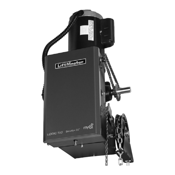
Logic 5.0 Commercial Door Operator
NOT FOR RESIDENTIAL USE
• Please read this manual and the enclosed safety materials completely, prior to installation
and use!
• This product is to be installed and serviced by a trained door systems technician only.
• A LiftMaster Monitored Entrapment Protection (LMEP) Device is REQUIRED for B2, T, TS,
and FSTS wiring types.
• Upon completion of installation, test entrapment protection device(s) prior to placing the
operator into active use.
• These operators are compatible with myQ
2 YEAR WARRANTY
Serial #
Installation Date
LiftMaster
300 Windsor Drive
Oak Brook, IL 60523
INSTALLATION MANUAL
®
Models T, APT, H, J, HJ, GH, and GT
and Security+ 2.0
accessories.
®
®
Publicité
Table des Matières
Dépannage

Manuels Connexes pour LiftMaster LOGIC 5.0 T


Sommaire des Matières pour LiftMaster LOGIC 5.0 T
- Page 1 • This product is to be installed and serviced by a trained door systems technician only. • A LiftMaster Monitored Entrapment Protection (LMEP) Device is REQUIRED for B2, T, TS, and FSTS wiring types. • Upon completion of installation, test entrapment protection device(s) prior to placing the operator into active use.
- Page 2 UL 325 requires all commercial door operators to be either constant pressure to close or be equipped with a primary external monitored entrapment protection device. LiftMaster is the leading brand of professionally installed commercial door operators and access control products for businesses ®...
-
Page 3: Table Des Matières
Troubleshooting Radio Functionality ..... 41 ENTRAPMENT PROTECTION 21-22 LiftMaster Monitored Entrapment Protection (LMEP) ..21 WIRING DIAGRAMS 42-43 Install the LiftMaster Monitored Entrapment Logic (Ver. -
Page 4: Safety Information
13. This door operator is not intended to replace door locks. operator mechanisms. With enough force, a door without a door lock can be opened. LiftMaster always recommends the use of door locks to properly secure a door. SAVE THESE INSTRUCTIONS . -
Page 5: Trolley Operators
Hardware box (includes fasteners, track spacers, trolley, door arm assembly, front idler and header mounting bracket) 3-Button control station with MAS LED LiftMaster Monitored Entrapment Protection (LMEP)* Trolley drive chain: #48 for 1/2 HP, #41 for 3/4 HP and higher (all GT models) NOTE: The tracks are shipped separately. - Page 6 OPERATOR SPECIFICATIONS MAXIMUM DOOR AREA (SQ . FT .) MODEL T MODEL APT 24 ga. 24 ga. 20 ga. 16 ga. 20 ga. 16 ga. 22 ga. 22 ga. Steel Steel Steel Steel Steel Steel Fiberglass Alum. Wood Alum. Wood Doors Doors Doors...
- Page 7 WEIGHTS AND DIMENSIONS MODELS T AND APT Hanging Weight: 80-110 lbs. 13.13” (33.35 cm) *Door Height Plus 4 feet (1.2 m) (minimum) 4" (10.16 cm) 10.5” (26.67 cm) Highest Point of Door Travel *20.5" (52.07 cm) - For operators manufactured before February of 2018 with a caliper brake, add 3-1/2" (8.9 cm) (Standard on APT, T 3/4 and T 1 HP models;...
-
Page 8: Assembly
ASSEMBLY ASSEMBLE THE OPERATOR (MODELS T AND GT) NOTE: For Model APT assembly refer to page 10. Install the track spacers evenly over the length of the track. HARDWARE Fasten the spacers to the track with bolt (A) and flange hex nuts (B). -
Page 9: Install The Chain (Models T And Gt)
INSTALL THE CHAIN (MODELS T AND GT) Position the trolley 2 inches (5.1 cm) away from the front idler. Attach the chain to the trolley threaded shaft using the master link. Run the chain along the track to the operator. Wrap the chain around the operator drive sprocket. -
Page 10: Assemble The Operator (Model Apt)
ASSEMBLE THE OPERATOR (MODEL APT) Install the track spacers evenly over the length of the track. HARDWARE Fasten the spacers to the track with bolt (A) and flange hex nuts (B). Flange Hex Nut Install the front idler in the second set of holes on the end of Bolt 3/8"-16 x 3/4"... -
Page 11: Typical Installation
TYPICAL INSTALLATION INSTALL THE HEADER BRACKET The trolley operator is generally mounted over the center of the To prevent possible SERIOUS INJURY or DEATH: door. However, off center mounting may be required due to interfering structures or location of the door stile / top section •... -
Page 12: Attach The Track To The Header Bracket
ATTACH THE TRACK TO THE HEADER BRACKET AND HANG THE OPERATOR Align the track with the header bracket. To avoid possible SERIOUS INJURY from a falling operator: Insert the clevis pin through the track and header bracket holes. Secure with the fasteners. •... -
Page 13: Attach The Door Arm And Bracket
ATTACH THE DOOR ARM AND BRACKET Latch the door arm to the trolley. Make sure the open side of HARDWARE the notch on the door arm faces the door. Position the door bracket to the center line of the door and attach the door bracket to the door using appropriate hardware Flanged Hex Nut 3/8"-16 (2) Nylok Nut 3/8"-16 (1) -
Page 14: Hoist And Jackshaft Operators Carton Inventory
3-Button Control Station with MAS LED additional precautions MUST be taken to assure that proper door cable tension is present throughout the ENTIRE travel of LiftMaster Monitored Entrapment Protection (LMEP)* the door. Hoist hand chain (Models H, HJ and GH ONLY) - Page 15 MAXIMUM DOOR AREA (SQ . FT .) MODELS J, H, AND HJ MODEL GH 24 ga. 16 ga. 22 ga. 20 ga. 24 ga. 22 ga. 20 ga. 16 ga. Steel Steel Steel 18 ga. Steel Steel 18 ga. Steel Steel Steel Alum.
-
Page 16: Weights And Dimensions
WEIGHTS AND DIMENSIONS MODELS J, H AND HJ Hanging Weight: 80-110 lbs. Door Height Plus 4 feet (minimum) 14.5" A - Wall Mounting (36.83 cm) B - Bracket Mounting (rolling door) 16.16" (41.04 cm) 7.25" 3/8" Bolt (18.41 cm) 4.63" (11.76 cm) 7.5"... -
Page 17: Assembly
ASSEMBLY ASSEMBLE THE OPERATOR The wall or mounting surface MUST provide adequate support for the operator. To prevent possible SERIOUS INJURY or DEATH: The surface must: • DO NOT connect electric power until instructed to do so. • If the door lock needs to remain functional, install an interlock a. -
Page 18: Mounting
MOUNTING Place the door sprocket on the door shaft. Wrap the drive chain around the door sprocket and the drive sprocket then secure with the master link. Align the door and the drive sprockets. Insert keys and fasten the sprockets with the set screws (recommended torque for the set screws is 34-45 in/lb). -
Page 19: Wiring
WIRING To reduce the risk of SEVERE INJURY or DEATH: • ANY maintenance to the operator or in the area near the • ALL electrical connections MUST be made by a qualified operator MUST NOT be performed until disconnecting the individual. -
Page 20: Control Station
CONTROL STATION To prevent possible SERIOUS INJURY or DEATH from the user from coming in contact with the door while operating the controls. electrocution: • Install the entrapment warning placard on the wall next to the • Be sure power is NOT connected BEFORE installing the door control station in a prominent location visible from the door. -
Page 21: Entrapment Protection
A LiftMaster Monitored Entrapment Protection (LMEP) Device is • Be sure power is NOT connected to the door operator BEFORE required for most wiring types (refer to page 29). If a LiftMaster installing the photoelectric sensor(s). Monitored Entrapment Protection Device is not installed, constant •... -
Page 22: Install The Liftmaster Monitored Entrapment Protection (Lmep) Devices (Optional)
Black/White Black NOTE: Only one LiftMaster Monitored Entrapment Protection (LMEP) Device can be connected to the logic board. To attach additional LMEPs, a CPS3CARD option card is required. Secondary (non-monitored) entrapment protection devices (with normally open dry contact) should be wired to the EDGE and COMMON terminals. -
Page 23: Adjustment
ADJUSTMENT IMPORTANT SAFETY INSTRUCTIONS TO REDUCE THE RISK OF SEVERE INJURY OR DEATH: 1. READ AND FOLLOW ALL WARNINGS AND INSTRUCTIONS. 8. After ANY adjustments are made, the entrapment protection device(s) MUST be tested. Failure to adjust the operator 2. ALWAYS keep remote controls out of reach of children. properly may cause SEVERE INJURY and DEATH. -
Page 24: Clutch Adjustment (Belt Drive Model Operators)
CLUTCH ADJUSTMENT (BELT DRIVE MODEL OPERATORS) The Clutch System is designed to protect the door an motorized To avoid SERIOUS personal INJURY or DEATH from operator. It is NOT a substitute for an entrapment protection electrocution: device. • Disconnect electric power BEFORE performing ANY adjustments or maintenance. -
Page 25: Testing
LMEP Device connected the only mode of operation will be B2, D1 or E2. To Erase the LiftMaster Entrapment Protection (LMEP) Device, turn the selector dial to DIAG, push and hold the stop button until the MAS LED flashes. -
Page 26: Manual Release
MANUAL RELEASE EMERGENCY DISCONNECT SYSTEM MODELS GT AND T To prevent possible SERIOUS INJURY or DEATH from a falling TO DISCONNECT DOOR FROM OPERATOR door or arm: The door should be in the fully closed position if possible. • DISCONNECT electric power to the operator BEFORE manually Pull emergency release handle straight down. -
Page 27: Emergency Disconnect System Model H, Gh, J, And Hj
EMERGENCY DISCONNECT SYSTEM MODELS H, GH, J, AND HJ To prevent possible SERIOUS INJURY from a moving chain: • DISCONNECT electric power to the operator BEFORE manually These operators have provisions for manually operating the door operating your door. in case of emergency or power failure. Refer to the appropriate •... -
Page 28: Programming
Technology. The Current Sense Harness is required for operating seconds) only the appropriate LED’s will continue to be lit: LiftMaster Commercial Door Operators that offer this feature. The Between limits: 24Vac and STOP Current Sense Feature measures overcurrent and limits operation... -
Page 29: Determine And Set Wiring Type
LIFTMASTER MONITORED ENTRAPMENT PROTECTION (LMEP) LIFTMASTER MONITORED ENTRAPMENT PROTECTION (LMEP) DEVICE IS REQUIRED DEVICE IS RECOMMENDED A LiftMaster Entrapment Protection (LMEP) Device is required for A LiftMaster Entrapment Protection (LMEP) Device is the following wiring types. recommended for the following wiring types. -
Page 30: Myq® Smart Facility Access
SMART FACILITY ACCESS ® • A connected dock door operator provides complete visibility LiftMaster offers a connected experience for all sizes of businesses into dock operations including door event status, trailer and their access needs. presence, dock leveler status, truck restraint status, forklift myQ technology uses a 900Mhz signal to communicate securely sensing, and trailer location. -
Page 31: Programming Remote Controls
90 remote control devices and up to 30 keyless entry devices can be added. ® NOTE: The following programming requires a LiftMaster Monitored Entrapment Protection (LMEP) Device. STANDARD REMOTE CONTROL SINGLE BUTTON REMOTE CONTROL PROGRAMMED AS A SINGLE BUTTON CONTROL (SBC) 1. - Page 32 PROGRAMMING REMOTE CONTROLS (CONTINUED) Open Close Stop 3. While holding STOP and CLOSE, press and hold OPEN. 4. Release all three buttons once the MAS LED on the 3BCS has lit. (For the MAS LED on the 3BCS to light, it must be wired to the L5 Operator Control Board.) 5.
-
Page 33: Maintenance Alert System (Mas)
PROGRAMMING REMOTE CONTROLS (CONTINUED) REMOTE CONTROL PROGRAMMING FEATURE ERASING REMOTE CONTROLS Program Remote Controls from the 3-button control station Press and hold the RADIO button on the logic board until the (3BCS) (continued) RADIO LED flashes rapidly (approximately 5 seconds). All remote controls will be erased. -
Page 34: Timer-To-Close
To prevent possible SEVERE INJURY or DEATH: • Activate door ONLY when it can be seen clearly, is properly • Install a LiftMaster Monitored Entrapment Protection (LMEP) adjusted and there are no obstructions to door travel. Device. • ALWAYS keep door in sight until completely closed. NEVER •... -
Page 35: Open Mid-Stop
Timer-To-Close feature. To enable this feature connect a treadle, photoelectric sensor or loop detector accessory to the SBC input and at a minimum one LiftMaster Monitored Entrapment Protection (LMEP) Device installed (refer to page 21). Wiring type must be set to TS or T (located on logic board). Before... -
Page 36: Maximum Run Timer (Mrt)
Remote controls and myQ devices will still be learned. g. Remote control programming via the 3-button station is deactivated. h. LiftMaster Monitored Entrapment Protection (LMEP) Device(s) will be deleted from the operator memory. NOTE: To delete LMEP Device(s) from the operator memory, the LMEP Device(s) must be disconnected prior to reset. -
Page 37: Maintenance
Shafts Check for wear and lubricate. Solenoid Brake Inspect brake pad LiftMaster Monitored Entrapment Check alignment and Protection (LMEP) functionality. Use SAE 30 Oil (Never use grease or silicone spray) . Inspect and service whenever a malfunction is observed or suspected. -
Page 38: Brake
BRAKE A drum brake comes standard on T, H, J, and HJ model operators with 3/4HP and larger motors. It comes adjusted from the factory, however, occasional adjustments may be necessary throughout the life of the brake. ADJUSTING DRUM BRAKE: 1. -
Page 39: Troubleshooting Guide
TROUBLESHOOTING GUIDE FAULT POSSIBLE CAUSE A RELAY CLICK IS HEARD WHEN This is normal operation. ➤ No action necessary. See Logic Board Overview (page 28) for more GIVEN A COMMAND SLIGHTLY information regarding current sense. BEFORE MOTOR MOVEMENT . RELAY LED'S ON BOARD FLASH IN UNISON WITH THE CLICK . -
Page 40: Troubleshooting Error Codes
Option card will not function Refer to accessories page for list of supported option option card receptacles. properly. card(s). 7 blinks LiftMaster Monitored Entrapment Normal operation (5 second Cleared when entrapment protection device is cleared Protection (LMEP) Device faulted constant pressure override or connected. -
Page 41: Troubleshooting Radio Functionality
TROUBLESHOOTING RADIO FUNCTIONALITY The error codes will display at the radio LED. NOTE: Radio receiver is compatible with SECURITY+ 2.0 remote controls and keyless entry devices. ® ERROR CODE DISPLAY SYMPTOM POSSIBLE PROBLEM CORRECTION Quick Flash No response from the remote Unlearned remote control - Reprogram the remote control. -
Page 42: Wiring Diagrams
WIRING DIAGRAMS LOGIC (VER. 5.0) 1 PHASE WIRING DIAGRAM Refer to page 21 for LiftMaster Monitored Entrapment Protection (LMEP) Device connections Wiring Diagrams... -
Page 43: Logic (Ver. 5.0) 3 Phase Wiring Diagram
LOGIC (VER. 5.0) 3 PHASE WIRING DIAGRAM - WITH CURRENT SENSING TECHNOLOGY Refer to page 21 for LiftMaster Monitored Entrapment Protection (LMEP) Device connections. Wiring Diagrams... -
Page 44: Accessories
ACCESSORIES ENTRAPMENT PROTECTION DEVICES MONITORED MONITORED CPS-U Dual-Sided Infrared Photoelectric Sensors CPS3CARD Safety Interface Card • NEMA 1 general purpose enclosure. Plug-in Interface card enables use of a second set • Dual-sided infrared sensors. of monitored photo eyes or edge with a Optical Edge System (OES) commercial door operator (also known as •... - Page 45 Wireless Keypad Able to be programmed with temporary access codes for visitors or delivery personnel. RADIO STAR1000 Commercial Access Control Receiver Connects up to 1000 LiftMaster remote controls. ® Supports suspending and unsuspending remote controls to withhold and reinstate access. 850LM Universal Receiver Featuring Security+ 2.0...
- Page 46 ACCESSORIES MOUNTING BRACKETS ADDITIONAL CONTROL ACCESSORIES Heavy gauge steel bracket for vertical or horizontal 10-12360 86LM (15' [4 .6 m]) 02-401M Antenna Extension Kit mount on either front or top of coil on a rolling door. 86LMT (25' [7 .6 m]) The antenna extension kit can be used with Has a variety of mounting hole patterns compatible EXT-ANT for maximum radio receiver range.
-
Page 48: Control Connection Diagram
Remove Factory Installed Jumper when Interlock is Used Edge Sensor All Wiring Types 2 OR MORE © 2022, LiftMaster All Rights Reserved Wi-Fi® is a trademark of Wi-Fi Alliance® App Store and the Apple and App Store logos are trademarks of Apple Inc. -
Page 49: Opérateur De Porte Commerciale Logic
• C e produit doit être installé et entretenu uniquement par un technicien qualifié en systèmes de portes. • Un dispositif de protection contre le piégeage surveillé LiftMaster (LMEP) est REQUIS pour les câblages B2, T, TS et FSTS. • Une fois l’installation terminée, testez le(s) dispositif(s) de protection contre le piégeage avant de mettre l’opérateur en service actif. - Page 50 La norme UL 325 exige que tous les opérateurs de portes commerciales soient à pression constante pour la fermeture ou qu’ils soient équipés d’un dispositif primaire de protection contre le piégeage contrôlé à l’extérieur. LiftMaster est la première marque d’opérateurs de portes commerciales et de produits de contrôle d’accès installés professionnellement ®...
- Page 51 Fonctionnalité de dépannage par radio . . . . . . . . . . . . . . . . . . . 41 Protection contre le piégeage surveillée LiftMaster (LMEP) . . . 21 DIAGRAMME DE CÂBLAGE...
-
Page 52: Consignes De Sécurité
. Avec suffisamment de force, une porte 7 . Ne portez JAMAIS de montres, de bagues ou de vêtements sans serrure peut être ouverte . LiftMaster recommande amples pendant l’installation ou l’entretien d’un opérateur . Ils toujours d’utiliser des serrures pour sécuriser correctement peuvent être pris dans les mécanismes de la porte ou de... -
Page 53: Opérateurs À Chariot
Poste de commande à 3 boutons avec DEL MAS Protection contre le piégeage surveillée LiftMaster (LMEP)* Chaîne d’entraînement du chariot : N° 48 pour 1/2 HP, n° 41 pour 3/4 HP et plus (tous les modèles GT) REMARQUE : Les rails sont expédiés séparément. - Page 54 SPÉCIFICATIONS DE L’OPÉRATEUR SURFACE MAXIMALE DE LA PORTE (PIEDS CARRÉS) MODÈLE T MODÈLE APT Acier Acier Acier Acier Acier Acier cal . 22 cal . 22 cal . 20 cal . 16 cal . 20 cal . 16 cal . 24 cal .
- Page 55 POIDS ET DIMENSIONS MODÈLES T ET APT Poids suspendu : 80-110 lb 13,13 po (33,35 cm) *Porte d’une hauteur supérieure à 4 pieds (1,2 m) (minimum) 4 po (10,16 cm) 10,5 po (26,67 cm) Point culminant du déplacement de la porte *20 .5 po (52,07 cm) - Pour les opérateurs fabriqués avant février 2018 avec un frein à étrier, ajoutez 3-1/2 po (8,9 cm) (standard sur les modèles APT, T 3/4 et T 1 HP;...
-
Page 56: Assemblage
ASSEMBLAGE ASSEMBLER L’OPÉRATEUR (MODÈLES T ET GT) REMARQUE : Pour le montage du modèle APT, voir page 10. Installez les entretoises de rail de manière régulière sur la MATÉRIEL longueur du rail . Fixez les entretoises au rail avec le boulon (A) et les écrous hexagonaux à... -
Page 57: Installer La Chaîne (Modèles T Et Gt)
INSTALLER LA CHAÎNE (MODÈLES T ET GT) Placez le chariot à 2 pouces (5,1 cm) de la poulie de tension avant . Fixez la chaîne à l’arbre fileté du chariot à l’aide du maillon principal . Faites passer la chaîne le long du rail jusqu’à l’opérateur . Enroulez la chaîne autour du pignon d’entraînement de l’opérateur . -
Page 58: Assembler L'opérateur (Modèle Apt)
ASSEMBLER L’OPÉRATEUR (MODÈLE APT) Installez les entretoises de rail de manière régulière sur la MATÉRIEL longueur du rail . Fixez les entretoises au rail avec le boulon (A) et les écrous hexagonaux à bride (B) . Écrou hexagonal à Installez la poulie de tension avant dans le deuxième ensemble Boulon 3/8 po bride 3/8 po -16 de trous à... -
Page 59: Installation Typique
INSTALLATION TYPIQUE INSTALLER LE SUPPORT DE LINTEAU L’opérateur sur chariot est généralement monté au-dessus du centre Pour éviter d’éventuelles BLESSURES GRAVES voire de la porte . Toutefois, un montage décentré peut être nécessaire MORTELLES : en raison de structures interférentes ou de l’emplacement du montant de la porte/support de la section supérieure . -
Page 60: Fixer Le Rail Au Support De Linteau
FIXER LE RAIL AU SUPPORT DE LINTEAU ET SUSPENDEZ L’OPÉRATEUR Alignez le rail avec le support de linteau . Pour éviter d’éventuelles BLESSURES GRAVES dues à la chute Insérez l’axe à épaulement dans les trous du rail et du support de l’opérateur : du linteau . -
Page 61: Fixer Le Bras Et Le Support De La Porte
FIXER LE BRAS DE LA PORTE ET LE SUPPORT Verrouillez le bras de la porte sur le chariot . Assurez-vous que le MATÉRIEL côté ouvert de l’encoche sur le bras de la porte fait face à la porte . Positionnez le support de porte sur la ligne centrale de la porte et fixez le support de porte à... -
Page 62: Opérateurs À Palan Et Arbre Secondaire
DOIVENT être prises pour s’assurer que la tension du câble de Protection contre le piégeage surveillée LiftMaster (LMEP)* la porte est correcte sur TOUTE la course de la porte . Chaîne manuelle de levage (modèles H, HJ et GH UNIQUEMENT) Pignon de porte (avec vis sans tête et clavette) - Page 63 SURFACE MAXIMALE DE LA PORTE (PIEDS CARRÉS) MODÈLES J, H ET HJ MODÈLE GH Acier Acier Acier Acier Acier Acier Acier Acier cal . 24 cal . 16 cal . 22 cal . 18 cal . 24 cal . 22 cal .
- Page 64 POIDS ET DIMENSIONS MODÈLES J, H ET HJ Poids suspendu : 80-110 lb Porte d’une hauteur supérieure à 4 pieds (minimum) 14,5 po A - Montage mural (36,83 cm) 16,16 po B - Montage du support (porte roulante) (41,04 cm) 7,25 po Boulon (18,41 cm) 4,63 po 3/8 po (11,76 cm)
-
Page 65: Assemblage
ASSEMBLAGE ASSEMBLER L’OPÉRATEUR Le mur ou la surface de montage DOIT fournir un support adéquat pour l’opérateur . Pour éviter d’éventuelles BLESSURES GRAVES voire MORTELLES : La surface doit : • NE branchez PAS l’alimentation électrique avant d’avoir reçu l’instruction de le faire . a . -
Page 66: Montage
MONTAGE Placez le pignon de porte sur l’arbre de porte . Enroulez la chaîne d’entraînement autour du pignon de la porte et du pignon d’entraînement, puis fixez-la avec le maillon principal . Alignez la porte et les pignons d’entraînement . Insérez les clavettes et fixez les pignons avec les vis de réglage (le couple recommandé... -
Page 67: Alimentation Et Mise À La Terre
CÂBLAGE Pour réduire le risque de BLESSURE GRAVE voire MORTELLE : • TOUTES les installations et connexions électriques DOIVENT être effectuées par une personne qualifiée . • TOUTE intervention sur l’opérateur ou dans la zone proche de l’opérateur DOIT SEULEMENT être effectuée après avoir •... -
Page 68: Poste De Commande
POSTE DE COMMANDE Pour éviter d’éventuelles BLESSURES GRAVES voire lorsqu’il actionne les commandes . MORTELLES par électrocution : • Installez la plaque d’avertissement relative au piégeage sur le • Assurez-vous que l’alimentation n’est PAS connectée AVANT mur à côté du poste de commande, à un endroit bien visible d’installer la commande de porte . -
Page 69: Protection Contre Le Piégeage Protection Contre Le Piégeage Surveillée Liftmaster (Lmep)
. • Les dispositifs LMEP sont SEULEMENT destinés à être utilisés avec les opérateurs de porte commerciale LiftMaster . Une utilisation avec TOUT autre produit annule la garantie . • Si un capteur de bord est utilisé sur une porte coulissante horizontale, placez un ou plusieurs capteurs de bord sur le bord avant et le bord arrière . -
Page 70: Installer Les Dispositifs De Protection Contre Le Piégeage Surveillés Liftmaster (Lmep) (En Option)
Reportez-vous toujours aux instructions d’installation incluses avec les dispositifs de protection contre le piégeage LiftMaster (LMEP) . Si un dispositif de protection contre le piégeage surveillé LiftMaster n’est pas installé, une pression constante de fermeture sera requise du poste de commande . -
Page 71: Réglage
RÉGLAGE CONSIGNES DE SÉCURITÉ IMPORTANTES POUR RÉDUIRE LE RISQUE DE BLESSURES GRAVES VOIRE MORTELLES : 1 . LISEZ ET SUIVEZ TOUS LES AVERTISSEMENTS ET TOUTES personne et de tout obstacle . LES INSTRUCTIONS . 8 . Après TOUT réglage, le ou les dispositifs de protection contre 2 . -
Page 72: Réglage De L'embrayage (Opérateurs De Modèles Àentraînement Par Courroie)
RÉGLAGE DE L’EMBRAYAGE (OPÉRATEURS DE MODÈLES À ENTRAÎNEMENT PAR COURROIE) Pour éviter des BLESSURES corporelles GRAVES voire Le système d’embrayage est conçu pour protéger la porte et MORTELLES par électrocution : l’opérateur motorisé . Il ne remplace PAS un dispositif de protection •... -
Page 73: Test
TEST Lors du test de l’opérateur, celui-ci doit être réglé sur le type de câblage C2 (réglage par défaut d’usine) . Mettez l’opérateur sous tension . Pour éviter des BLESSURES GRAVES voire MORTELLES : Lorsque l’opérateur est sous tension, toutes les DEL s’allument, à •... -
Page 74: Déclenchement Manuel
DÉCLENCHEMENT MANUEL SYSTÈME DE DÉCONNEXION D’URGENCE DES MODÈLES GT ET T Pour éviter les risques de BLESSURE GRAVE voire MORTELLE dus POUR DÉCONNECTER LA PORTE DE L’OPÉRATEUR à la chute d’une porte ou d’un bras : La porte doit être en position complètement fermée si possible . •... -
Page 75: Système De Déconnexion D'urgence, Modèles Apt
SYSTÈME DE DÉCONNEXION D’URGENCE, MODÈLES H, GH, J ET HJ Pour éviter d’éventuelles BLESSURES GRAVES causées par une chaîne en mouvement : Ces opérateurs sont dotés de dispositifs permettant d’actionner • DÉBRANCHEZ l’alimentation électrique de l’opérateur AVANT manuellement la porte en cas d’urgence ou de panne de courant . de faire fonctionner manuellement votre porte . -
Page 76: Programmation
Position complètement fermée : 24 Vca, ARRÊT, CLS et SLS commerciale de LiftMaster qui offrent cette caractéristique . La fonction de détection de courant mesure la surintensité et limite le Position complètement ouverte : 24 Vca, ARRÊT et OLS fonctionnement dans des conditions de courant élevé... -
Page 77: Déterminer Et Régler Le Type De Câblage
IL EST RECOMMANDÉ D’UTILISER UN DISPOSITIF DE PROTECTION (LMEP) EST NÉCESSAIRE CONTRE LE PIÉGEAGE LIFTMASTER SURVEILLÉ (LMEP) Un dispositif de protection contre le piégeage LiftMaster (LMEP) est Un dispositif de protection contre le piégeage LiftMaster (LMEP) est requis pour les types de câblage suivants . -
Page 78: Programmation Des Dispositifs Myq
® Facility Management aura le même mot de passe. Wi-Fi . (voir Accessoires, page 45) . 1 . Appelez le service clientèle de LiftMaster au 800 .323 .2276 pour Application myQ activer un compte Smart Facility Mangement . Téléchargez l’application myQ et suivez les instructions à l’écran pour 2 . -
Page 79: Programmation Des Télécommandes
PROGRAMMATION DES TÉLÉCOMMANDES Le récepteur radio intégré à 3 canaux Security+ 2 .0 permet d’ajouter jusqu’à 90 télécommandes et jusqu’à 30 dispositifs d’entrée sans clé . ® REMARQUE : La programmation suivante nécessite un dispositif LMEP. TÉLÉCOMMANDE STANDARD TÉLÉCOMMANDE À BOUTON UNIQUE PROGRAMMÉE COMME UNE COMMANDE À... -
Page 80: Programmation Des Télécommandes (Suite)
PROGRAMMATION DES TÉLÉCOMMANDES (SUITE) Ouverture Fermeture Arrêt 3 . Tout en maintenant STOP et CLOSE (fermeture), appuyez et maintenez OPEN (ouverture) . 4 . Relâchez les trois boutons lorsque la DEL MAS du 3BCS s’est allumée . (Pour que la DEL MAS du 3BCS s’allume, elle doit être câblée à... -
Page 81: Système D'alerte D'entretien (Mas)
PROGRAMMATION DES TÉLÉCOMMANDES (SUITE) FONCTION DE PROGRAMMATION DE LA TÉLÉCOMMANDE EFFACEMENT DES TÉLÉCOMMANDES Programmer des télécommandes à partir du poste de commande à Appuyez et relâchez le bouton RADIO sur la carte logique (la DEL 3 boutons (3BCS) (suite) RADIO clignote rapidement puis s’éteint, environ 5ºsecondes) . Pour désactiver cette fonction : Toutes les télécommandes seront effacées . -
Page 82: Minuterie De Fermeture (Ttc)
Exigences : Doit avoir au moins un dispositif de protection contre le relâchez le bouton CLOSE (fermeture) quatre fois pendant 60 secondes, piégeage surveillé LiftMaster (LMEP) installé (voir page 21) . Le type de puis appuyez et relâchez le bouton OPEN (ouverture) 10 fois câblage doit être réglé... -
Page 83: Arrêt À Mi-Ouverture
à l’entrée du SBC et au moins un dispositif de protection contre le piégeage surveillé LiftMaster (LMEP) installé (voir page 21) . Le type de câblage doit être réglé sur TS ou T (situé... -
Page 84: Minuterie De Fonctionnement Maximal (Mrt)
. h . Le(s) dispositif(s) de protection contre le piégeage surveillé(s) LiftMaster (LMEP) sera(ont) supprimé(s) de la mémoire de l’opérateur . REMARQUE : Pour supprimer le ou les dispositifs LMEP de la mémoire de l’opérateur, le ou les dispositifs LMEP doivent être déconnectés avant la réinitialisation. -
Page 85: Entretien
Inspecter les plaquettes de frein Protection contre le piégeage Vérifiez l’alignement et surveillée LiftMaster (LMEP) la fonctionnalité . Utilisez de l’huile SAE 30 (n’utilisez jamais de graisse ou de Inspectez et procédez à l’entretien chaque fois qu’un silicone en vaporisateur) . -
Page 86: Frein
FREIN Un frein à tambour est fourni de série sur les opérateurs des modèles T, H, J et HJ équipés de moteurs de 3/4 CV et plus . Il est livré réglé en usine, mais des réglages occasionnels peuvent être nécessaires pendant la durée de vie du frein . RÉGLAGE DU FREIN À... -
Page 87: Guide De Dépannage
GUIDE DE DÉPANNAGE ERREUR CAUSE POSSIBLE CORRECTION UN CLIC DE RELAIS EST ENTENDU Cela est normal . ➤ Aucune action nécessaire . Voir Vue d’ensemble de la carte logique (page 28) pour plus LORSQU’ON DONNE UNE COMMANDE d’information sur la détection du courant . UN PEU AVANT LE MOUVEMENT MOTEUR . -
Page 88: Codes D'erreur De Dépannage
7 clignotements Le dispositif de protection contre le Fonctionnement normal (une Effacé lorsque le dispositif de protection contre le piégeage piégeage surveillé LiftMaster (LMEP) commande de pression constante est effacé ou connecté . est en panne ou a été retiré pendant de 5 secondes est nécessaire pour... -
Page 89: Dépannage De La Fonctionnalité Radio
DÉPANNAGE DE LA FONCTIONNALITÉ RADIO Les codes d’erreur s’affichent sur la DEL de la radio . REMARQUE : Le récepteur radio est compatible avec les télécommandes SECURITY+ 2.0 et les dispositifs d’entrée sans clé. ® CODE AFFICHAGE SYMPTÔME PROBLÈME ÉVENTUEL CORRECTION D’ERREUR Clignotement Pas de réponse de... -
Page 90: Diagramme De Câblage
(RO) (BL) dispositif de Protection Dispositif contre le piégeage Ouv. de détection avec surveillance auxiliaire LiftMaster (LMEP) Ferm. Arr. Poste à 3 boutons Bouton unique ouv./ferm. INTERR. ANNUL. MINUT. (BLEU) (JAUNE) REMARQUE : Terre Seulement 3 phases. -
Page 91: Diagramme De Câblage Triphasé Logic (Vers . 5 .0)
Dispositif dispositif de Protection (ROUGE) (BLANC) Ouvir contre le piégeage de détection avec surveillance auxiliaire LiftMaster (LMEP) Fermer Poste à 3 boutons Arrêt Bouton unique ouv./ferm. INTERR. ANNUL. MINUT. Retirer le cavalier pour installer le verrouillage extérieur de porte... -
Page 92: Accessoires
ACCESSOIRES DISPOSITIFS DE PROTECTION CONTRE LE PIÉGEAGE SURVEILLÉ SURVEILLÉ CPS-U Capteurs photoélectriques infrarouges à double face CPS3CARD Carte d’interface de sécurité • Boîtier à usage général NEMA 1 . La carte d’interface enfichable permet d’utiliser un • Capteurs infrarouges à double face . deuxième jeu d’yeux photo ou de capteurs de bord Optical Edge System (OES) •... - Page 93 825LM Commande de lumière à distance Contrôlez automatiquement votre éclairage avec votre ouvre-porte commerciale, une télécommande Security+ 2 .0 ou une passerelle Internet LiftMaster ® ® 02-110 Se branche sur n’importe quelle prise à l’intérieur . Poste de commande à clé...
- Page 94 ACCESSOIRES SUPPORTS DE FIXATION ACCESSOIRES SUPPLÉMENTAIRES DE COMMANDE Support en acier de forte épaisseur pour un montage 10-12360 86LM (15 pi [4,6 m]) 02-401M Kit d’extension d’antenne vertical ou horizontal sur l’avant ou le haut de la bobine 86LMT (25 pi [7,6 m]) Le kit d’extension d’antenne peut être utilisé avec d’une porte roulante .
-
Page 96: Diagramme De Connexion Des Commandes
Capteur d'arrêt Tous les types de câblage 2 OUPLUS © 2022, LiftMaster Tous droits réservés . Wi-Fi® est une marque de commerce de Wi-Fi Alliance® L’App Store et les logos Apple et App Store sont des marques commerciales d’Apple Inc .