Table des Matières
Publicité
Les langues disponibles
Les langues disponibles
Liens rapides
FW
P1.00
IS240 Rev.03 30/07/2021
B70/2ML
centrale di comando per cancelli battenti
Istruzioni originali
IT -
Istruzioni ed avvertenze per l'installatore
EN -
Instructions and warnings for the installer
DE -
Anweisungen und Hinweise für den Installateur
FR -
Instructions et consignes pour l'installateur
ES -
Instrucciones y advertencias para el instalador
PT -
Instruções e advertências para o instalado
NL -
Aanwijzingen en waarschuwingen voor de installateur
PL -
Publicité
Table des Matières

Manuels Connexes pour Roger Technology B70/2ML


Sommaire des Matières pour Roger Technology B70/2ML
- Page 1 P1.00 IS240 Rev.03 30/07/2021 B70/2ML centrale di comando per cancelli battenti Istruzioni originali IT - Istruzioni ed avvertenze per l’installatore EN - Instructions and warnings for the installer DE - Anweisungen und Hinweise für den Installateur FR - Instructions et consignes pour l’installateur...
-
Page 3: Table Des Matières
INDICE • INDEX • INDEX • INDEXER • ÍNDICE • ÍNDICE • INDEX • INDEKS ITALIANO DEUTSCH Avvertenze generali Allgemeine Sicherheitshinweise Dichiarazione di Conformità Konformitätserklärung Simbologia Symbole Descrizione prodotto Produktbeschreibung Caratteristiche tecniche prodotto Technische Daten des Produkts Descrizione dei collegamenti Beschreibung der Anschlüsse Installazione tipo Art der Installation... - Page 4 ESPAÑOL DUTCH Advertencias generales Algemene waarschuwingen Declaración de Conformidad Verklaring van Overeenstemming Símbolos Symbolen Descripción del producto Beschrijving product Características técnicas del producto Technische kenmerken product Descripción de las conexiones Beschrijving aansluitingen Instalación básica Type installatie Conexiones eléctricas Elektrische aansluitingen Comandos y accesorios Bedieningen en accessoires Teclas de función y pantalla...
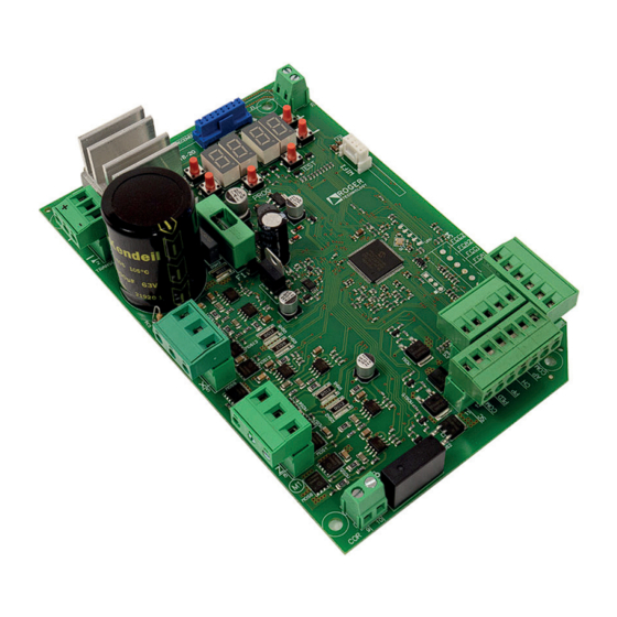
- Page 5 Illustrazioni e schemi - Pictures and schemes - Bilder und Pläne Illustrations et schémas - Ilustraciones y esquemas - Ilustrações e esquemas P1.00 Display a 4 cifre e 6 tasti di programmazione 4 digit display and 6 programming Fusibile F15A buttons Fuse F15A Connettore ad innesto...
- Page 6 H93/RX20/I FUSIBILE RICEVITORE RADIO FUSE RADIO RECEIVER F15A MOTORE 2 MOTOR 2 TRANSFORMER PROG TEST F3.15mA WIFI FUSIBILE FUSE F3.15A ISEL COM PED AP COM MOTORE 1 MOTOR 1...
- Page 7 RG58 max 10 m Antenna ISEL STOP COM PED AP COM (*) Vmedia=12Vdc; Vmax=30Vdc (*) Vaverage=12Vdc; Vmax=30Vdc Utilizzo alternativo dell'uscita COR (par. diverso da 00). Alternative use of COR output (par. different from 00). Luce di cortesia CH IU SO Courtesy light CL O SE D 230 Vac 100W...
- Page 8 COLLEGAMENTO CON 1 COPPIA FOTOCELLULE SINCRONIZZATE (MODALITÁ NORMALE, SOLO COPPIA MASTER) CONNECTION WITH 1 SYNCHRONISED PHOTOCELL PAIR (NORMAL MODE, MASTER PAIR ONLY) ROSSO = libero da jumper RED = jumper free JUMPER DI SINCRONIZZAZIONE ISEL (PER MASTER) SYNCHRONISATION JUMPER 1 2 3 1 2 3 (FOR MASTER) JUMPER DI ALLINEAMENTO...
- Page 9 COLLEGAMENTO CON 2 COPPIE FOTOCELLULE SINCRONIZZATE (MODALITÁ NORMALE, 1 MASTER E 1 SLAVE) CONNECTION WITH 2 SYNCHRONISED PHOTOCELL PAIRS (NORMAL MODE, 1 MASTER AND 1 SLAVE) ROSSO = libero da jumper RED = jumper free JUMPER DI SINCRONIZZAZIONE (PER MASTER) SYNCHRONISATION JUMPER 1 2 3 1 2 3...
- Page 10 TEST FOTOCELLULE · PHOTOCELLS TEST ( COLLEGAMENTO CON 1 COPPIA FOTOCELLULE SINCRONIZZATE (MODALITÁ NORMALE, SOLO COPPIA MASTER) CONNECTION WITH 1 SYNCHRONISED PHOTOCELL PAIR (NORMAL MODE, MASTER PAIR ONLY) ROSSO = libero da jumper RED = jumper free JUMPER DI SINCRONIZZAZIONE (PER MASTER) SYNCHRONISATION JUMPER 1 2 3...
- Page 11 TEST FOTOCELLULE · PHOTOCELLS TEST ( COLLEGAMENTO CON 2 COPPIE FOTOCELLULE SINCRONIZZATE (MODALITÁ NORMALE, 1 MASTER E 1 SLAVE) CONNECTION WITH 2 SYNCHRONISED PHOTOCELL PAIRS (NORMAL MODE, 1 MASTER AND 1 SLAVE) ROSSO = libero da jumper RED = jumper free JUMPER DI SINCRONIZZAZIONE (PER MASTER) SYNCHRONISATION JUMPER...
- Page 12 BATTERY SAVING ( BATTERY SAVING + TEST FOTOCELLULE · PHOTOCELLS TEST ( COLLEGAMENTO CON 1 COPPIA FOTOCELLULE SINCRONIZZATE (MODALITÁ NORMALE, SOLO COPPIA MASTER) CONNECTION WITH 1 SYNCHRONISED PHOTOCELL PAIR (NORMAL MODE, MASTER PAIR ONLY) ROSSO = libero da jumper RED = jumper free JUMPER DI SINCRONIZZAZIONE (PER MASTER) SYNCHRONISATION JUMPER...
- Page 13 BATTERY SAVING ( BATTERY SAVING + TEST FOTOCELLULE · PHOTOCELLS TEST ( COLLEGAMENTO CON 2 COPPIE FOTOCELLULE SINCRONIZZATE (MODALITÁ NORMALE, 1 MASTER E 1 SLAVE) CONNECTION WITH 2 SYNCHRONISED PHOTOCELL PAIRS (NORMAL MODE, 1 MASTER AND 1 SLAVE) ROSSO = libero da jumper RED = jumper free JUMPER DI SINCRONIZZAZIONE (PER MASTER)
- Page 14 INSTALLAZIONE SU SERIE AY (AYRON) • MOTORE 1 (AY250M) AY SERIES (AYRON) INSTALLATION • MOTOR 1 (AY250M) F2 FUSIBILE H93/RX20/I RICEVITORE RADIO FUSE F15A RADIO RECEIVER TRANSFORMER PROG TEST F3.15mA WIFI FUSIBILE FUSE F3.15A FUSIBILE FUSE ISEL COM PED AP COM B71/BC 2 batteries 12 Vdc 1,2 Ah...
- Page 15 COLLEGAMENTI CARICA BATTERIA SU SERIE AY (AYRON) • MOTORE 1 (AY250M) BATTERY CHARGER CONNECTION ON AY (AYRON) SERIES • MOTOR 1 (AY250M) collegamento secondario del trasformatore secondary transformer connection 2 batterie opzionali, installate su motore 2 2 optional batteries, installed on motor 2 12 Vdc 1,2 Ah type AGM...
- Page 16 INSTALLAZIONE BATTERIA SU SERIE AY (AYRON) • MOTORE 2 (AY250S) BATTERY INSTALLATION ON AY (AYRON) SERIES • MOTOR 2 (AY250S) TRANSFORMER PROG TEST F3.15mA WIFI ISEL COM PED AP COM MOTORE 2 MOTORE 1 MOTOR 2 MOTOR 1 T10A 12V 1.2Ah 12V 1.2Ah...
- Page 17 INSTALLAZIONE IN BOX (B70/2ML/BOX) BOX INSTALLATION (B70/2ML/BOX) PRIMARIO TRASFORMATORE MONOFASE POT. 150 VA 50/60 Hz Cod. 702_10/0 FUSIBILE CEI 61558-2-6 FUSE SECONDARIO 230 Vac (B70/2ML/BOX) 115 Vac FUSIBILE FUSE (B70/2ML/BOX/115) FUSE F15A T10A 5x20 TRANSFORMER B71/BC/INT WIFI PROG TEST F3.15mA...
-
Page 18: Avvertenze Generali
La mancata osservanza delle informazioni contenute nel presente manuale può dare luogo a infortuni personali o danni all’apparecchio. ROGER TECHNOLOGY declina qualsiasi responsabilità derivante da un uso L’installazione, i collegamenti elettrici e le regolazioni devono essere effettuati da norme vigenti. - Page 19 EN 12453 e EN 12445. ROGER TECHNOLOGY declina ogni responsabilità qualora vengano installati In caso sia attiva la funzione uomo presente dovrà essere cura dell’installatore in gomma, la velocità di chiusura del varco ed in generale tutti gli accorgimenti deve essere posto in una posizione che garantisca il controllo e il funzionamento di utilizzo 1 o 2).
-
Page 20: Dichiarazione Di Conformità
Smaltire e riciclare gli elementi dell’imballo secondo le disposizioni delle norme vigenti. nell’uso dell’impianto. Dichiarazione CE di Conformità DICHIARA che la centrale di comando B70/2ML | 20. -
Page 21: Simbologia
Simbolo per lo smaltimento del prodotto secondo la direttiva RAEE, vedere capitolo 20. Descrizione prodotto La centrale B70/2ML a 24V controlla in modalità sensorless 1 o 2 motori ROGER brushless per applicazioni su ante di dimensioni medie, per uso residenziale. Attenzione all’impostazione del parametro . -
Page 22: Caratteristiche Tecniche Prodotto
La somma degli assorbimenti di tutti gli accessori collegati non deve superare i dati di potenza massima indicati in tabella. I dati sono garantiti SOLO con accessori originali ROGER TECHNOLOGY. L'utilizzo di accessori non originali può causare malfunzionamenti. ROGER TECHNOLOGY declina ogni responsabilità per installazioni errate o non conformi. -
Page 23: Descrizione Dei Collegamenti
Descrizione dei collegamenti Installazione tipo loro caratteristiche tecniche. Cavo consigliato Alimentazione di rete Motore 1 Cavo 3x2,5 mm² (max 10 3x4 mm² (max 30 m) * Motore 2 Cavo 3x2,5 mm² (max 10 3x4 mm² (max 30 m) F4ES/F4S Cavo 5x0,5 mm (massimo 20 m) F4ES/F4S Cavo 3x0,5 mm... -
Page 24: Collegamenti Elettrici
Collegamenti elettrici Prevedere sulla rete di alimentazione un interruttore o un sezionatore onnipolare con distanza di apertura dei contatti uguale o superiore a 3 mm; posizionare il sezionatore in posizione OFF, e scollegare le eventuali batterie tampone, prima di eseguire l’installazione e le periodiche operazioni di manutenzione. -
Page 25: Comandi E Accessori
Comandi e accessori Le sicurezze con contatto N.C., se non installate devono essere ponticellate ai morsetti COM, oppure disabilitate modificando i parametri N.A. (Normalmente Aperto) N.C. (Normalmente Chiuso) CONTATTO DESCRIZIONE 9(COR) 9(COR) • • 20(+LAM) 19(COM) É possibile selezionare le impostazioni di prelampeggio dal parametro e le modalità... - Page 26 CONTATTO DESCRIZIONE 16(AP) 17(COM) Ingresso comando di apertura (N.A.). ATTENZIONE: l'attivazione persistente del comando di apertura non permette la richiusura automa tica; il conteggio del tempo di richiusura automatica riprende al rilascio del comando di apertura. 15(CH) 17(COM) Ingresso comando di chiusura (N.A.). 14(PP) 17(COM) 13(PED)
-
Page 27: Tasti Funzione E Display
Tasti funzione e display TASTO DESCRIZIONE Parametro successivo Parametro precedente DOWN Incremento di 1 del valore del parametro DOWN Decremento di 1 del valore del para metro PROG Apprendimento della corsa PROG TEST TEST Attivazione modalità TEST • Premere i tasti UP •... -
Page 28: Modalità Visualizzazione Di Stato Comandi E Sicurezze
Modalità visualizzazione di stato comandi e sicurezze STATO DEI COMANDI STATO DELLE SICUREZZE STATO DEI COMANDI: Le indicazioni dei comandi (segmenti AP=apre, parziale, ORO=orologio) sono normalmente spente. accende il segmento PP). STATO DELLE SICUREZZE: FT2=fotocellule, COS = bordo sensibile, STOP) sono POWER STOP sono in allarme o non collegate. -
Page 29: Apprendimento Della Corsa
Apprendimento della corsa 10.1 Prima di procedere 1. Selezionare il modello dell’automazione installata con il parametro Motore HIGH SPEED TIPO SELEZIONE MODELLO CONFIGURAZIONI MOTORE SERIE AYRON BE20/200 MONOS4 2. Selezionare il numero di motori installati con il parametro NON aver abilitato la funzione a uomo presente ( OPEN STOP CLOSE... -
Page 30: Procedura Di Apprendimento
TEST VEDI CAPITOLO 14 e 15 1 click finchè ... TEST VEDI PROCEDURA DI TEST PROG APPRENDIMENTO AP P- CAP. 11.2 CHIUSO 1 click Tener premuto Sì TEST VEDI PROCEDURA DI APPRENDIMENTO CAP. 11.2 1 click 10.2 Procedura di apprendimento PROG PROG AP P-... -
Page 31: Indice Dei Parametri
Indice dei parametri VALORE DI PARAM. DESCRIZIONE PAGINA FABBRICA VEDI Selezione modello automazione CAP.10 Richiusura automatica dopo il tempo di pausa (da cancello completamente aperto) Prelampeggio Funzione condominiale sul comando di apertura parziale (PED) Abilitazione funzione a uomo presente Regolazione del rallentamento MOTORE 1 in apertura e chiusura Regolazione del rallentamento MOTORE 2 in apertura e chiusura Regolazione controllo posizione ANTA 1 Regolazione controllo posizione ANTA 2... - Page 32 VALORE DI PARAM. DESCRIZIONE PAGINA FABBRICA Regolazione dello spazio di accostamento del MOTORE 2 in APERTURA e CHIUSURA Impostazione numero di tentativi di richiusura automatica dopo intervento del Impostazione modalità di funzionamento della fotocellula in apertura (FT1) Impostazione modalità di funzionamento della fotocellula in chiusura (FT1) Modalità...
- Page 33 VALORE DI PARAM. DESCRIZIONE PAGINA FABBRICA Visualizzazione contatore manovre eseguite Visualizzazione contatore ore manovra Visualizzazione contatore giorni di accensione Password Protezione cambio password...
-
Page 34: Menù Parametri
Menù parametri VALORE DEL PARAMETRO PARAMETRO Selezione modello automazione ATTENZIONE! Una errata impostazione può causare anomalie nel funzionamento dell’automazione. NOTA: nel caso di ripristino ai parametri standard di fabbrica, il valore del parametro deve essere reimpostato manualmente. SERIE AYRON IRREVERSIBILE HIGH SPEED BE20/200 IRREVERSIBILE MONOS4... - Page 35 Abilitato. Il cancello funziona tenendo premuti i comandi apre (AP) o chiude (CH). Al rilascio del comando il cancello si ferma. Spia cancello aperto / Funzione test fotocellule e “battery saving” aperto. Lampeggia velocemente durante la manovra di chiusura. Impostare a NOTA: Impostare a morsetto SC per ridurre il consumo di batteria.
- Page 36 Regolazione tempo di chiusura automatica Il conteggio inizia a cancello aperto e dura per il tempo impostato. Scaduto il tempo, il cancello chiude automaticamen te. L’intervento delle fotocellule rinnova il tempo. tempo di richiusura automatica riprende al rilascio del comando di apertura. da 00 a 90 s di pausa.
- Page 37 Regolazione sensibilità intervento sugli ostacoli MOTORE 1 di impatto sugli ostacoli risulta essere troppo elevata, diminuire il valore del parametro parametro, ripetere la procedura di apprendimento. = forza di impatto sugli ostacoli minima ... = forza di impatto sugli ostacoli massima. Coppia motore media.
- Page 38 Impostazione modalità di funzionamento della fotocellula FT1 in apertura INVERSIONE IMMEDIATA. Se si attiva la fotocellula durante la manovra di apertura, il cancello inverte immediatamente. ad aprire. INVERSIONE RITARDATA. Con fotocellula oscurata il cancello si ferma. Liberata la fotocellula il cancello chiude. Impostazione modalità...
- Page 39 Selezione del tipo di contatto (N.C. oppure 8k2 Ohm) sugli ingressi FT1/FT2/ST N.C. N.C. N.C. N.C. N.C. N.C. N.C. N.C. N.C. Selezione del tipo di test fotocellule sull'ingresso FT1 Selezione del tipo di test fotocellule sull'ingresso FT2 Test fotocellule disabilitato. Test fotocellule abilitato SOLO in apertura.
- Page 40 APERTURA. CHIUSURA. STOP. Il parametro viene ignorato. viene ignorato. PASSO PASSO con conferma di sicurezza APERTURA PARZIALE con conferma di sicurezza APERTURA con conferma di sicurezza CHIUSURA con conferma di sicurezza Per evitare che la pressione involontaria di un tasto del radiocomando attivi erroneamente il cancello, viene richiesta una conferma di •...
- Page 41 Da 2 a 9 min di attesa. Selezione delle limitazioni nel funzionamento a batteria NOTA: diverso da segnalazione mediante uscita COR (se parametri opportunamente impostati). Quando la tensione di batteria scende alla soglia selezionata con par. , la centrale accetta solo comandi di apertura e non richiude mai.
-
Page 42: Cambio Password
Visualizzazione contatore ore manovra NOTA: i valori indicati in tabella sono valori puramente indicativi. Quando si supera il limite di ore manovra impostato da ogni 1500 ore manovra). ATTENZIONE: per manovra si intende ogni attivazione del motore in apertura. Sul display appare non si effettua la manutenzione dell'impianto e si resetta l'allarme. -
Page 43: Segnalazione Degli Ingressi Di Sicurezza E Dei Comandi (Modalità Test)
Segnalazione degli ingressi di sicurezza e dei comandi (modalità TEST) DISPLAY POSSIBILE CAUSA INTERVENTO DA SOFTWARE INTERVENTO TRADIZIONALE Contatto STOP di sicurezza aper Installare un pulsante di STOP (N.C.) oppure parametro ponticellare il contatto ST con il contatto Errata selezione del parametro COM. -
Page 44: Segnalazione Allarmi E Anomalie
Segnalazione allarmi e anomalie SEGNALAZIONE PROBLEMA POSSIBILE CAUSA INTERVENTO ALLARME LED POWER spento Manca alimentazione di rete. LED POWER spento Fusibili bruciati. Sostituire il fusibile. Controllare fusibili F1, F2 e F3. Si raccomanda di estrarre e reinserire il fusibile sola mente in assenza di tensione di rete. -
Page 45: Modalità Info
PER USCIRE 1 click DALLA MODALITA’ x5 s La Modalità INFO permette di visualizzare alcuni valori misurati dalla centrale B70/2ML. Dalla modalità “Visualizzazione comandi e sicurezze” e con motori fermi, premere per 5 s il tasto TEST. Parametro Funzione rispetto alla lunghezza totale. -
Page 46: Sblocco Meccanico
Esempio: 1-PREMERE 2-RILASCIARE 3-RI-PREMERE APRE CHIUDE APRE CHIUDE APRE CHIUDE oppure oppure oppure oppure entro 1 s • Il MOTORE in oggetto si attiva in apertura premendo il tasto "FRECCIA SU", si attiva in chiusura premendo il tasto "FRECCIA GIÙ". •... -
Page 47: Collaudo
RECUPERO POSIZIONE CON CENTRALINA NON ALIMENTATA (BLACK OUT) E POSIZIONE DELLE ANTE INTERMEDIA (NON COMPLETAMENTE CHIUSA O NON COMPLETAMENTE APERTA) trovino le ante, dopo un prelampeggio di 5 secondi si attiva la manovra di chiusura, a bassa velocità. Al successivo comando le ante effettuano la manovra di apertura a bassa velocità per ripristinare la normale modalità di funzionamento. -
Page 48: Informazioni Aggiuntive E Contatti
Informazioni aggiuntive e contatti Tutti i diritti relativi alla presente pubblicazione sono di proprietà esclusiva di ROGER TECHNOLOGY. comportino un cambio di versione FW. In assenza di revisione del manuale di istruzioni, si intende che queste istruzioni valgono per questa e successive versioni FW della centrale di comando. -
Page 49: General Safety Precautions
ROGER TECHNOLOGY is not liable for failure to observe the good practices in during use. The safety devices (photocells, sensing edges, emergency stops, etc.) must be in force, the good practices criteria, the installation environment, the operating logic of the system and the forces generated by the motorised door or gate. - Page 50 The installer is required to measure impact forces and select on the control unit the appropriate speed and torque values to ensure that the door or gate ROGER TECHNOLOGY cannot be held responsible for any damage or injury caused by the installation of incompatible components which compromise the safety and correct operation of the device.
-
Page 51: Declaration Of Conformity
Dispose of and recycle the packaging items according to the provisions of the laws in force. These instructions must be kept and must be made available to any other persons authorised to use the installation. Declaration CE of Conformity DECLARES that the B70/2ML | 20. Place Date Signature... -
Page 52: Symbols
Symbol for the product disposal according to the WEEE directive, see chapter 20. Product description The 24V B70/2ML control unit controls 1 or 2 ROGER brushless motors in sensorless mode for applications on medium sized gate leaves for residential use. Ensure that the parameter is set correctly. -
Page 53: Technical Characteristics Of Product
The total of the absorption values of all the accessories connected must not exceed the maximum power values shown in the table. The values are guaranteed with original ROGER TECHNOLOGY accessories ONLY. All the connections are protected by fuses (refer to the table). The courtesy light requires an external fuse. -
Page 54: Description Of Connections
Description of connections Typical installation It is the installer's responsibility to verify the adequacy of the cables in relation to the devices used in the installation and their technical characteristics. Recommended cable Power supply double insulated cable Motor 1 Cable 3x2,5 mm² (max 10 3x4 mm²... -
Page 55: Electrical Connections
Electrical connections buffer batteries before performing any cleaning or maintenance operations. Ensure that an adequate residual current circuit breaker with a 0.03 A threshold and a suitable practices and in compliance with applicable legislation. located inside the control panel box. Strip the insulation from the ends of the power cable wires which will be connected to the Measure the voltage on the primary mains power connection with a tester. -
Page 56: Commands And Accessories
Commands and Accessories If not installed, safety devices with NC contacts must be jumpered at the COM terminals, or disabled by modifying the parameters N.A. (Normally Open) . N.C. (Normally Closed). CONTACT DESCRIPTION 9 (COR) Output (potential free contact) for connecting courtesy light. 9 (COR) •... - Page 57 CONTACT DESCRIPTION 16(AP) 17(COM) Open control signal input (N.O.). IMPORTANT: persistent activation of the opening command prevents automatic reclosure; the auto matic reclosure time count is resumed when the opening command is released. 15(CH) 17(COM) Close command input (N.O.). 14(PP) 17(COM) Step by step mode command input (N.O.).
-
Page 58: Function Buttons And Display
Function buttons and display BUTTON DESCRIPTION Next parameter DOWN Previous parameter Increase value of parameter by 1 DOWN Decrease value of parameter by 1 PROG Programme travel PROG TEST TEST Activate TEST mode • Press the UP buttons to view the parameter you intend to modify. •... -
Page 59: Command And Safety Device Status Display Mode
Command and safety device status display mode COMMAND STATUS SAFETY DEVICE STATUS COMMAND STATUS: The command status indicators on the display (segments AP = open, PP = step mode, CH = close, PED = partial opening, ORO= clock) are normally off. -
Page 60: Travel Acquisition
Travel acquisition For the system to function correctly, the gate travel must be acquired by the control. 10.1 Before starting 1. Select the automation system model installed with the parameter KEY: HIGH SPEED Motor MOTOR SELECTION MODEL CONFIGURATIONS TYPE AYRON SERIES NOTE: for gate leaves up to 2.5 m BE20/200 NOTE: for gate leaves up to 3 m... -
Page 61: Acquisition Procedure
TEST SEE CHAPTER 14 e 15 1 click Until... TEST PROG ACQUISITION TEST PROCEDURE AP P- CHAP. 11.2 1 click CLOSE Press and hold on TEST ACQUISITION PROCEDURE CHAP. 11.2 1 click 10.2 Acquisition procedure: PROG PROG AP P- AU to x4 s 1 click MOTOR 1... -
Page 62: Index Of Parameters
Index of parameters FACTORY PARAM. DESCRIPTION PAGE DEFAULT Selecting automation system model CHAP. 10 Automatic closure after pause time (from gate completely open) Selecting step mode control function (PP) Condominium function for partial open command (PED) Enabling operator present function MOTOR 1 Setting deceleration during opening and closing MOTOR 2 Setting deceleration during opening and closing Adjusting LEAF 1 position control... - Page 63 FACTORY PARAM. DESCRIPTION PAGE DEFAULT Number of automatic closure attempts after activation of sensing edge or obstacle detection (crush protection) Setting photocell mode during gate opening (FT1) Setting photocell mode during gate closing (FT1) Photocell (FT1) mode with gate closed Setting photocell mode during gate opening (FT2) Setting photocell mode during gate closing (FT2) Photocell (FT2) mode with gate closed...
- Page 64 FACTORY PARAM. DESCRIPTION PAGE DEFAULT View manoeuvre hour counter View control unit days on counter Password Password change protection...
-
Page 65: Parameters Menu
Parameters menu PARAMETER PARAMETER VALUE Selecting automation system model WARNING! If this parameter is not set correctly, the automation system may not function properly. N.B.: in the event of a reset to restore the default parameters, this parameter must be set again manually. AYRON SERIES - IRREVERSIBLE HIGH-SPEED gear motor with articulated arm BE20/200 - IRREVERSIBLE arm piston with worm screw MONOS4 - IRREVERSIBLE telescopic arm piston... - Page 66 Gate open indicator / photocell test function and “battery saving” The indicator is off when the gate is closed, and steadily lit during manoeuvres and when the gate is open. If the gate is stopped in an intermediate position, the lamp extinguishes twice every 15 seconds. Set to When the gate is completely open or closed, the control unit deactivates any accessories connected to terminal SC to reduce battery consumption.
- Page 67 Setting automatic closing time The timer starts from the gate open state and continues for the set time. Once the set time is reached, the gate closes automatically. The timer count restarts if a photocell is triggered. IMPORTANT: persistent activation of the opening command prevents automatic reclosure; the automatic reclosure time count is resumed when the opening command is released.
- Page 68 Setting obstacle impact force sensitivity MOTOR 1 If the reaction time to obstacle impact force is too long, reduce the value of the parameter. If the impact force exerted on obstacles is too high, reduce the value of parameter N.B: repeat the acquisition procedure after any change made to this parameter. = minimum obstacle impact force ...
- Page 69 TEMPORARY STOP. The gate stops as long as the photocell is obstructed. The gate resumed opening when the photocell is cleared. DELAYED REVERSE. The gate stops if the photocell is obstructed. The gate closes when the photocell is cleared. Setting photocell mode during gate closing (FT1) DISABLED.
- Page 70 N.C. N.C. Selecting the type of photocell test on input FT1 This parameter is visible if is set. If the photocell test is enabled, the control unit will check the photocells connected to input FT1 are working properly. Selecting the type of photocell test on input FT2 This parameter is visible if is set.
- Page 71 • seconds by pressing CHB on the remote control. Press CHB to activate partial opening. Selecting courtesy light mode NOTE: The parameter is not visible if par. is other than Disabled. ACTIVE. The light remains lit for the entire duration of the manoeuvre. From 3 to 90 s.
- Page 72 Battery consumption selection normal. Selection of the battery operation management Setting a value different than a battery voltage level check is activated. The desired operation type can be selected via parameter and an error alert can be activated through the COR output via parameter The control unit always accepts commands until the battery is completely exhausted.
- Page 73 View control unit days on counter The number consists of the values of the parameters from N.B.: The values shown in the table are indicative only. Days with unit switched on. = 123 days. Password Setting a password prevents unauthorised persons from accessing the settings. With password protection active ( Only a single password is used to control access to the gate automation system.
-
Page 74: Safety Input And Command Status (Test Mode)
Safety input and command status (TEST mode) DISPLAY POSSIBLE CAUSE ACTION BY SOFTWARE PHYSICAL CORRECTIVE ACTION The safety STOP contact is open. Check that parameter is set cor Install a STOP button (NC) or jumper the Incorrect setting of parameter rectly ST contact with the COM contact. -
Page 75: Alarms And Faults
Alarms and faults PROBLEM ALARM POSSIBLE CAUSE ACTION POWER LED off No mains power. Check the mains power cable. POWER LED off Fuses blown. Replace fuse. Always disconnect from mains Check fuses F1, F2 and F3. power before removing fuses. Input mains power voltage fault. - Page 76 THE INFO MODE x5 s INFO mode may be used to view certain parameters measured by the B70/2ML controller. Press and hold the TEST button for 5 seconds from the “View command signals and safety devices” mode with the motor stationary. The control unit displays the following parameters and the corresponding measured values in...
-
Page 77: Mechanical Release
Example: 1-PRESS 2-RELEASE 3-RE-PRESS OPEN CLOSE OPEN CLOSE APRE CLOSE within 1 s • THE MOTOR in question is activated on opening by pressing the "UP ARROW" key, or on closure by pressing the "DOWN ARROW" key. • the button, release within 1 second and then press and hold. The motor stops as soon as the button is released. WARNING: during the check, the motor revolution count (position) is updated but the gate leaf alignment control function may cause problems. -
Page 78: Initial Testing
POSITION RECOVERY WITH CONTROL UNIT NOT POWERED (BLACK OUT) AND INTERMEDIATE POSITION OF LEAVES (NOT COMPLETELY CLOSED OR NOT COMPLETELY OPEN) and a blackout occurs, when the mains voltage returns, in whatever position the leaves are, At the next command, the gate leaves perform the opening manoeuvre at low speed to restore normal operating mode. is at , upon receipt of a command, the repositioning procedure begins, which will be completed when the leaves have performed a complete run without... -
Page 79: Additional Information And Contact Details
ROGER TECHNOLOGY is the exclusive proprietor holder of all rights regarding this publication. or any alterations to this document are prohibited without express prior authorised from by ROGER TECHNOLOGY. ROGER TECHNOLOGY reserves the right to modifying or perfecting the product, which will not imply a FW version change. -
Page 80: Allgemeine Sicherheitshinweise
Die Nichtbeachtung der in diesem Handbuch enthaltenen Informationen kann Verletzungen oder Schäden am Gerät zur Folge haben. ROGER TECHNOLOGY lehnt jede Haftung für Schäden, die durch unsachgemäßen oder nicht bestimmungsgemäßen, den Angaben dieses Handbuchs nicht entsprechenden Gebrauch verursacht werden, ab. - Page 81 am beweglichen Teil installieren. Es ist zu beachten, dass gemäß der Norm UNI EN 12635 alle Anforderungen der Normen EN 12604 und EN 12453 erfüllt und gegebenenfalls auch überprüft werden müssen. Die Europäischen Richtlinien EN 12453 und EN 12445 legen die Mindestanforderungen an die Nutzungssicherheit von automatischen Türen und Toren fest.
-
Page 82: Konformitätserklärung
Diese Anleitung muss aufbewahrt und eventuellen neuen Benutzern der Anlage übergeben werden. Konformitätserklärung V.to (TV) ERKLÄRT, dass die Steuerung B70/2ML mit den von den folgenden Gemeinschaftsrichtlinien vorgegebenen Die beiden letzten Ziffern des Jahres, in dem die | Datum Unterschrift... -
Page 83: Symbole
Die Geschwindigkeiten, die Verlangsamungen und die Verzögerungen beim Öffnen und Schließen je nach Art der Installation einstellen und auf die korrekte Überlagerung der Flügel achten. ROGER TECHNOLOGY lehnt jede Haftung für Schäden, die durch unsachgemäßen oder nicht bestimmungsgemäßen, den Angaben dieses Handbuchs nicht entsprechenden Gebrauch verursacht werden, ab. -
Page 84: Technische Daten Des Produkts
EIN, 50% AUS). Das anzuschließende Gerät muss daher einer maximalen Spannung von 30Vdc standhalten. Die Summe der Stromaufnahmen aller angeschlossenen Zubehörteile darf nicht die, in der Tabelle angegebenen, ROGER TECHNOLOGY übernimmt keine Haftung bei falschen oder nicht geeigneten Installationen. Alle Anschlüsse sind durch Sicherungen geschützt, siehe Tabelle. Die Zugangsbeleuchtung erfordert eine externe... -
Page 85: Beschreibung Der Anschlüsse
Beschreibung der Anschlüsse Art der Installation Es liegt in der Verantwortung des Installateurs, die Eignung der Kabel in Bezug auf die in der Installation verwendeten Geräte und deren technische Eigenschaften zu überprüfen. Empfohlene Kabel Stromversorgung Motor 1 Kabel 3x2,5 mm² (max 10 3x4 mm²... -
Page 86: Elektrische Anschlüsse
Elektrische Anschlüsse Am Versorgungsnetz einen allpoligen Schalter oder Trennschalter mit Öffnungsabstand der Kontakte von mindestens 3 mm einbaue. Den Trennschalter auf OFF stellen und alle Prüfen, ob sich vor der Elektroanlage ein geeigneter Fehlerstromschutzschalter mit und der geltenden Normen. (braun), N (blau), speziellen Kabelbinder befestigen. -
Page 87: Befehle Und Zubehör
Befehle und Zubehör Wenn die Sicherheitseinrichtungen mit Öffnerkontakt nicht installiert sind, müssen sie an den Klemmen COM überbrückt oder durch Änderung der Parameter des erweiterten Menüs deaktiviert werden. KONTAKT BESCHREIBUNG 9 (COR) 10 Ausgang für Anschluss an die Zugangsbeleuchtung W (Abb. 3). 9 (COR) •... - Page 88 KONTAKT BESCHREIBUNG 27(ST) 26(COM) Die Öffnung des Sicherheitskontaktes verursacht das Anhalten der Bewegung. HINWEIS: Der Kontakt wird werkseitig von ROGER TECHNOLOGY überbrückt. – 36 (ANT) 35 Anschluss Antenne für steckbaren Funkempfänger. 10 m. ANMERKUNG: Das Kabel ohne Verbindungsstellen verwenden. 16(AP) 17(COM) nicht möglich;...
-
Page 89: Funktionstasten Und Display
Funktionstasten und Display TASTE BESCHREIBUNG Nächster Parameter DOWN Vorhergehender Parameter Erhöhung des Parameterwerts um 1 DOWN Verringerung des Parameterwerts um 1 PROG Lernlauf PROG TEST TEST • Die Tasten UP drücken, um den zu bearbeitenden Parameter anzuzeigen. • Die Tasten + und – drücken, um den Wert des Parameters zu ändern. Der Wert beginnt zu blinken. •... -
Page 90: Anzeige Des Status Von Befehlen Und Sicherheitseinrichtungen
Anzeige des Status von Befehlen und Sicherheitseinrichtungen STATUS DER BEFEHLE: STATUS DER SICHER- Die Anzeigen der Befehle (Segmente AP = Öffnen, HEITSEINRICHTUNGEN STATUS DER BEFEHLE PP = Schrittbetrieb, CH = Schließen, PED = Teilöffnung, ORO = Uhr) sind normalerweise ausgeschaltet. Sie Wenn ein Befehl zum Schrittbetrieb gegeben wird, schaltet sich das Segment PP ein). -
Page 91: Lernlauf
Lernlauf Für einen korrekten Betrieb muss erneut ein Lernlauf durchgeführt werden. 10.1 Zunächst 1. Das installierte Modell des Antriebs mit dem Parameter auswählen. LEGENDE: HIGH SPEED Motor AUSWAHL MODELL KONFIGURATIONEN MOTOR BAUREIHE AYRON BE20/200 MONOS4 2. Die Zahl der installierten Motoren mit dem Parameter auswählen. -
Page 92: Einlernverfahren
TEST Siehe Kapitel 14 und 15 Nein 1 Klick Bis ... TEST PROG TEST EINLERNVERFAHREN AP P- Kap. 11.2 Nein 1 Klick GESCHLOSSEN Drücken TEST EINLERNVERFAHREN Kap. 11.2 1 Klick 10.2 Einlernverfahren PROG PROG AP P- AU to x4 s 1 click VERZÖGERUNGSZEIT MOTOR 1... -
Page 93: Index Der Parameter
Index der Parameter STANDARD- PARAM. BESCHREIBUNG SEITE WERTE SIEHE Auswahl des Antriebsmodells KAP. 10 Automatisches Schließen nach Ablauf der Pausenzeit (bei vollständig geö netem Tor) Automatische Schließung nach einem Stromausfall (Blackout) Funktionsauswahl Steuerbefehl Schrittbetrieb (PP) Vorblinken Wohnanlagebetrieb auf Befehl zur Teilö nung (PED) Aktivieren des Totmannbetriebs. - Page 94 STANDARD- PARAM. BESCHREIBUNG SEITE WERTE Einstellung des Annäherungswegs von MOTOR 1 beim ÖFFNEN und SCHLIESSEN Einstellung des Annäherungswegs von MOTOR 2 beim ÖFFNEN und SCHLIESSEN Einstellung der Zahl der Versuche des automatischen Wiederschließens (Quetschschutz) Einstellung Funktionsweise der Lichtschranke beim Ö nen (FT1) Einstellung Funktionsweise der Lichtschranke beim Schließen (FT1) Funktionsweise der Lichtschranke (FT1) bei geschlossenem Tor Einstellung Funktionsweise der Lichtschranke beim Ö...
- Page 95 STANDARD- PARAM. BESCHREIBUNG SEITE WERTE Anzeige Bewegungszähler Anzeige Stundenzähler Bewegung Anzeige Zähler Einschalttage des Steuergeräts Password Passwort ändern...
-
Page 96: Menü Parameter
Menü Parameter WERT DES PARAMETER PARAMETERS Auswahl des Antriebsmodells ACHTUNG! Eine falsche Einstellung kann Funktionsstörungen des Antriebs verursachen. ANMERKUNG: Im Falle der Rücksetzung auf die werkseitigen Standardparameter, muss der Wert des Parameters von Hand neu eingestellt werden. BAUREIHE AYRON SELBSTHEMMENDER Getriebemotor mit Gelenkarm HIGH SPEED BE20/200 SELBSTHEMMENDER MONOS4 SELBSTHEMMENDER Automatische Schließung nach Auslösen nach der Pausenzeit (bei vollständig... - Page 97 Kontrollleuchte Schwingtor offen / Funktion Lichtschrankentest und “battery saving” Die Kontrollleuchte ist bei geschlossenem Tor ausgeschaltet. Dauerhaft eingeschaltet während der Bewegungen und wenn das Tor geöffnet ist. Die Kontrollleuchte blinkt langsam während der Öffnungsbewegung. Sie schaltet sich dauerhaft ein, wenn das Tor ganz geöffnet ist.
- Page 98 Einstellung der automatischen Schließzeit Die Zählung beginnt bei offenem Tor und dauert die eingestellte Zeit. Nach Ablauf dieser Zeit schließt das Tor automa tisch. Die Auslösung der Lichtschranken lässt die Zählung der Zeit von vorne beginnen. Zeitzählung der automatischen erneuten Schließung beginnt wieder bei Loslassen des Öffnungsbefehls. von 00 bis 90 s Pause.
- Page 99 - MOTOR 1 Wenn die Reaktionszeit auf die Aufprallkraft auf Hindernisse zu lang ist, den Wert des Parameters verringern. Wenn die Aufprallkraft auf den Hindernissen zu groß ist, die Werte des Parameters verringern. 01 = minimale Aufprallkraft auf den Hindernissen ... 10 = maximale Aufprallkraft auf den Hindernissen. tallation geeignet sind.
- Page 100 Einstellung Funktionsweise der Lichtschranke beim Öffnen (FT1) DEAKTIVIERT. Die Lichtschranke ist nicht aktiv oder die Lichtschranke ist nicht installiert. STOPP. Das Tor hält an und bleibt bis zum nächsten Befehl stehen. SOFORTIGE UMKEHR. Wenn die Lichtschranke während der Öffnungsbewegung aktiviert wird, kehrt das Tor sofort um. VORÜBERGEHENDER STOPP.
- Page 101 Auswahl der Kontaktart (Öffnerkontakt oder 8k2 Ohm) an den Eingängen FT1/FT2/ST richtungen angeschlossen werden, die statt eines Öffnerkontakts einen Kontakt mit 8.2kOhm verwenden. Die Steue N.C. N.C. N.C. N.C. N.C. N.C. N.C. N.C. N.C. Auswahl des Fotozellen-Testtyps am Eingang FT1 Der Parameter ist sichtbar, wenn man oder einstellt.
- Page 102 STOPP. Zugangsbeleuchtung. Der Ausgang COR wird von der Fernbedienung gesteuert. Das Licht bleibt eingeschaltet, solange die Fernbedienung aktiv ist. Der Parameter wird ignoriert. wird ignoriert. SCHRITTBETRIEB mit Sicherheitsbestätigung. TEILÖFFNUNG mit Sicherheitsbestätigung. ÖFFNUNG mit Sicherheitsbestätigung. SCHLIESSUNG mit Sicherheitsbestätigung. Um den ungewollten Druck einer Taste der Fernbedienung und damit die Aktivierung des Tors zu vermeiden, wird eine Sicherheitsbe •...
- Page 103 Auswahl der Einschränkungen im Batteriebetrieb ANMERKUNG: Der Parameter ist nur sichtbar, wenn der Parameter nicht ist. Keine Einschränkungen der Befehle, wenn die Batteriespannung auf den ausgewählten Schwellenwert fällt. Es ist entsprechend eingestellt sind). Wenn die Batteriespannung auf den mit Parameter eingestellten Schwellenwert fällt, akzeptiert das Steuergerät nur Öffnungsbefehle und schließt sich nicht wieder.
-
Page 104: Passwort Ändern
Anzeige Stundenzähler Bewegung Die Zahl besteht aus den Werten der Parameter von ANMERKUNG: Die in der Tabelle angegebenen Werte dienen nur zur Veranschaulichung. Wenn die von 1500 Stunden Bewegung). ACHTUNG: Unter Bewegung versteht sich jede Öffnenaktivierung des Motors. Auf dem Display erscheint und, bei stillstehenden Motoren, die Blinkleuchte schaltet sich in regelmäßigen Abstän den ein (1 s ein 4 s aus), bis die Wartung der Anlage durchgeführt und der Alarm zurückgesetzt wird. -
Page 105: Meldung Der Sicherheitseingänge Und Der Befehle
Meldung der Sicherheitseingänge und der Befehle (TEST- Modus) MASSNAHME ÜBER HERKÖMMLICHE DISPLAY MÖGLICHE URSACHE SOFTWARE MASSNAHME STOPP Die korrekte Auswahl des Parame Eine STOPP Falsche Auswahl des Parameters ters prüfen. oder den Kontakt ST mit dem Kontakt COM überbrücken. Sicherheitsleiste COS nicht oder Falls nicht benutzt oder man sie aus Falls nicht benutzt oder man sie aus falsch angeschlossen. -
Page 106: Meldung Von Alarmen Und Störungen
Meldung von Alarmen und Störungen PROBLEM ALARMMELDUNG MÖGLICHE URSACHE BETRIEB POWER Keine Netzstromversorgung. Das Netzstromversorgungskabel überprüfen. ausgeschaltet POWER Sicherung durchgebrannt. Sicherung ersetzen. Die Sicherung nur bei ausge Die Sicherungen F1, F2 und F3 prü schalteter Netzspannung herausziehen. ausgeschaltet fen. Störung der Eingangsspannung. Die Netzspannung ausschalten, 10 s warten und Initialisierung des Steuergeräts fehl geschlagen. -
Page 107: Diagnostik - Betriebsart Info
ZU GEHEN x5 s In der Betriebsart INFO werden einige Messwerte der Steuerung B70/2ML angezeigt. In der Betriebsart „Bedienelemente und Sicherheitsvorrichtungen anzeigen“ und bei ausgeschaltetem Motor, die Taste TEST 5 Sekunden lang gedrückt halten. Das Steuergerät zeigt nacheinander die folgenden Parameter und den... -
Page 108: Mechanische Entriegelung
Beispiel: 1-DRÜCKEN 2-LOSSLASSEN 3-WIEDER DRÜCKEN ÖFFNET SCHLIEßT ÖFFNET SCHLIEßT ÖFFNET SCHLIEßT oder oder oder oder innerhalb von 1 s • Der betreffende MOTOR aktiviert sich beim Öffnen durch Druck der Taste "PFEIL NACH OBEN", und aktiviert sich beim Schließen durch Druck der Taste "PFEIL NACH UNTEN". -
Page 109: Modus Zur Korrektur Der Position
KORREKTUR DER POSITION BEI AUSGESCHALTETEM STEUERGERÄT (STROMAUSFALL) UND ZWISCHENPOSITION DER TORFLÜGEL (NICHT VOLLSTÄNDIG GESCHLOSSEN ODER NICHT VOLLSTÄNDIG OFFEN) gestellt ist und ein Stromausfall auftritt, aktiviert sich bei Wiederherstellung der Geschwindigkeit. Funktionsweise wiederherzustellen. steht, beginnt nach Unterbrechung durchgeführt haben. Abnahmeprüfung wählen, mit denen die Tür bzw. das motorisierte Tor die von den Richtlinien EN 12453 und EN 12445 festgesetzten Vorschriften einhält. -
Page 110: Zusätzliche Informationen Und Kontakte
Scannen, Überarbeitungen oder Änderungen sind ohne vorherige schriftliche Zustimmung durch ROGER TECHNOLOGY ausdrücklich verboten. ROGER TECHNOLOGY behält sich das Recht vor, jederzeit Änderungen oder Verbesserungen am Produkt vorzunehmen, die keine FW Versionsänderung mit sich führen. Wird keine Revision der Gebrauchsanweisungen durchgeführt, bedeutet dies, dass die Anweisungen sowohl für diese als für die nachfolgenden FW Versionen der Steuereinheit gelten. -
Page 111: Consignes Générales De Sécurité
La non observation des informations contenues dans ce manuel peut causer des accidents à des personnes ou des dommages à l'appareil. ROGER TECHNOLOGY décline toute responsabilité dérivant d'une utilisation impropre ou différente de celle pour laquelle l'installation est destinée et indiquée dans le présent manuel. - Page 112 à la porte motorisée de rentrer dans les limites établies par les normes EN 12453 et EN 12445. ROGER TECHNOLOGY décline toute responsabilité au cas où seraient installés des composants incompatibles pour la sécurité et le bon fonctionnement. Si la fonction « homme présent » est activée, l'installateur devra se charger déformable en caoutchouc, la vitesse de fermeture de l'embrasure et en général...
-
Page 113: Déclaration De Conformité
Déclaration de conformité CE Le soussigné M. Dino Florian, représentant légal de Roger Technology - Via Botticelli 8, 31021 Mogliano V.to (TV) DÉCLARE que la centrale de commande B70/2ML est conforme aux dispositions établies par les directives | 20. -
Page 114: Symboles
20. Description produit La centrale B70/2ML à 24 V commande 1 ou 2 moteurs sans balais ROGER en mode sans capteur pour des applications sur des vantaux de taille moyenne, à usage résidentiel. provoquer des erreurs de fonctionnement de l’automatisme. -
Page 115: Caractéristiques Techniques Produit
La somme des absorptions de tous les accessoires branchés ne doit dépasser les données de puissance maximale indiquées dans le tableau. Les données sont garanties UNIQUEMENT avec des accessoires d'origine ROGER TECHNOLOGY. L'utilisation d'accessoires non d'origine peut provoquer des dysfonctionnements. ROGER TECHNOLOGY décline toute responsabilité pour les installations incorrectes ou non conformes. extérieur. -
Page 116: Description Des Raccordements
Description des raccordements Installation type utilisés dans l'installation et à leurs caractéristiques techniques. Câble conseillé Alimentation Moteur 1 Câble 3x2,5 mm² (max 10 3x4 mm² (max 30 m) * Moteur 2 Câble 3x2,5 mm² (max 10 3x4 mm² (max 30 m) F4ES/F4S Câble 5x0,5 mm (max 20 m) -
Page 117: Pour Le Bon Fonctionnement Des Automatisations Brushless, La Tension
(24 V) sont séparés. Les câbles doivent être à double isolement, les dégainer à proximité des bornes de raccordement correspondantes et les bloquer à l'aide de colliers non fournis par ROGER TECHNOLOGY. DESCRIPTION Installation sur moteur AYRON. -
Page 118: Commandes Et Accessoires
ATTENTION ! Il est recommandé d’utiliser les photocellules série R90/F4ES, G90/F4ES ou T90/F4S. 27(ISEL) 26(COM) 27(ST) 26(COM) Entrée commande d’arrêt (N.F. ou 8.2 kOhm). L’ouverture du contact de sécurité provoque l’arrêt du mouvement. REMARQUE : Le contact est shunté en usine par ROGER TECHNOLOGY. . Contact à l’entrée N.F. (normalement fermé). –... - Page 119 CONTACT DESCRIPTION 36 (ANT) 35 Branchement antenne pour récepteur radio à prise. éviter de faire des jonctions sur le câble. 16(AP) 17(COM) Entrée commande d'ouverture (N.A.). ATTENTION : l'activation persistante de la commande d'ouverture ne permet pas la fermeture auto matique ;...
-
Page 120: Touches Fonction Et Écran
Touches fonction et écran TOUCHE DESCRIPTION DOWN DOWN PROG Programmation de la course PROG TEST TEST Activation modalité TEST • Appuyer sur les touches UP • Avec les touches + et - • Maintenir la touche + ou la touche - variation plus rapide. -
Page 121: Modalité Test
ÉTAT DES COMMANDES ÉTAT DES SÉCURITÉS ÉTAT DES COMMANDES : indications commandes (segments partielle, ORO=horloge) sont normalement éteintes. Elles s'allument à la réception d'une commande ÉTAT DES SÉCURITÉS : Les indications des sécurités (segments FT2=photocellules, COS = bord sensible, ou le point POWER STOP de STOP) sont normalement allumées. -
Page 122: Apprentissage De La Course
Apprentissage de la course 10.1 Avant de procéder LÉGENDE HIGH SPEED MOTEUR TYPE SÉLECTION MODÈLE CONFIGURATIONS MOTEUR SÉRIE AYRON REMARQUE : pour les vantaux jusqu’à 2,5 m BE20/200 REMARQUE : pour les vantaux jusqu’à 3 m MONOS4 REMARQUE : pour les vantaux jusqu’à 4 m moteurs. -
Page 123: Procédure D'apprentissage
TEST VOIR CHAPITRES 14 et 15 1 clic jusqu'à... TEST PROG TEST APPRENDISAGE DE AP P- LA COURSE Ch. 11.2 1 clic FERMÉE Appuyer TEST APPRENDISAGE DE LA COURSE Ch. 11.2 1 clic 10.2 Procédure d'apprentissage PROG PROG AP P- AU to x4 s 1 click... -
Page 124: Indice Des Paramètres
Indice des paramètres VALEURS PARAM. DESCRIPTION PAGE STANDARD VOIR CHAP. 11 Préclignotement Fonction copropriété sur la commande d’ouverture partielle (PED) Activation fonction homme présent Réglage du ralentissement MOTEUR 1 pendant ouverture et fermeture Réglage du ralentissement MOTEUR 2 pendant ouverture et fermeture Réglage contrôle de position VANTAIL 1 Réglage contrôle de position VANTAIL 2 Réglage de l’ouverture partielle (%) - Page 125 VALEURS PARAM. DESCRIPTION PAGE STANDARD Réglage de l’espace de rapprochement du MOTEUR 1 à l’OUVERTURE et FERMETURE Réglage de l’espace de rapprochement du MOTEUR 2 à l’OUVERTURE et FERMETURE Paramétrage modalité de fonctionnement de la photocellule en ouverture (FT1) Paramétrage modalités de fonctionnement de la photocellule en fermeture (FT1) Modalités de fonctionnement de la photocellule (FT1) avec portail fermée Paramétrage modalité...
- Page 126 VALEURS PARAM. DESCRIPTION PAGE STANDARD Mot de passe Changement mot de passe...
-
Page 127: Menu Paramètres
Menu paramètres VALEUR DU PARAMÈTRE PARAMÈTRE Sélection du modèle d'automatisme ATTENTION ! REMARQUE : manuellement. SÉRIE AYRON IRRÉVERSIBLE HIGH SPEED SÉRIE BE20 IRRÉVERSIBLE MONOS4 IRRÉVERSIBLE Refermeture automatique après après le temps de pause (à partir de le portail complètement ouverte) Désactivée. -
Page 128: Réglage Contrôle De Position Vantail
Voyant portail ouverte / fonction test photocellules et “battery saving” ouverte. Il clignote rapidement pendant la manoeuvre de fermeture. Si le portail est arrêtée en position intermédiaire, le voyant s'éteint deux fois toutes les 15 s. Paramétrer à pour réduire la consommation de la batterie. Réglage du ralentissement MOTEUR 1 pendant la manoeuvre de ouverture et fermeture Réglage du ralentissement MOTEUR 2 pendant la manoeuvre de ouverture et... -
Page 129: Activation Gestion Ouverture Avec Exclusion De La Fermeture Automatique
Réglage du temps de fermeture automatique Le comptage commence lorsque le portail est ouverte et dure pendant le temps paramétré. Le temps expiré, le portail se ferme automatiquement. L’intervention des photocellules renouvelle le temps. ATTENTION : l'activation persistante de la commande d'ouverture ne permet pas la fermeture automatique ; le compta ge du temps de fermeture automatique reprend au relâchement de la commande d'ouverture. -
Page 130: Réglage Sensibilité Force D'impact Sur Les Obstacles Moteur
Réglage sensibilité force d’impact sur les obstacles MOTEUR 1 REMARQUE : = force d'impact minimale sur les obstacles ... = force d'impact maximale sur les obstacles. tallation. Couple moteur moyen. Paramétrage conseillé pour le réglage des forces opérationnelles. = force d'impact minimale sur les obstacles ... = force d'impact maximale sur les obstacles. -
Page 131: Modalités De Fonctionnement De La Photocellule (Ft1) Avec Portail Fermée
Paramétrage modalité de fonctionnement de la photocellule en ouverture (FT1) DÉSACTIVÉE. La photocellule n'est pas active ou la photocellule n'est pas installée. ARRÊT. Le portail s'arrête et reste à l'arrêt jusqu'à la commande suivante. INVERSION IMMÉDIATE. Si la photocellule s'active pendant la manoeuvre d'ouverture, le portail s'inverse immédiatement. STOP TEMPORAIRE. - Page 132 Sélection du type de contact (N.F. ou 8k2 Ohm) sur les entrées FT1/FT2/ST N.C. N.C. N.C. N.C. N. C. N.C. N.C. N.C. N.C. Sélection du type d'essai photocellules sur l'entrée FT1 Sélection du type d'essai photocellules sur l'entrée FT2 Essai photocellules désactivé. Essai photocellules activé...
-
Page 133: Sélection Modalité De Fonctionnement Lumière De Courtoisie
ARRÊT est ignoré. est ignoré. • pression de la touche CHB de la radiocommande. Appuyer sur la touche CHB pour activer l'ouverture partielle. L’intermittence est réglée électroniquement par le clignotant. Intermittence lente. Intermittence lente en ouverture, rapide en fermeture. Sélection modalité de fonctionnement lumière de courtoisie REMARQUE : est différent de Désactivée. -
Page 134: Sélection Des Limitations Dans Le Fonctionnement Par Batterie
Sélection des limitations dans le fonctionnement par batterie REMARQUE : est différent de Aucune limitation aux commandes, lorsque la tension de batterie descend au seuil sélectionné. Il est possible d'activer Lorsque la tension de batterie descend au seuil sélectionné avec le par. , la centrale accepte uniquement des commandes d'ouverture et elle ne referme jamais. -
Page 135: Changement Mot De Passe
à les valeurs indiquées dans le tableau sont des valeurs purement indicatives. , le signal visuel d'entretien s'active (exem ATTENTION ! par manœuvre on entend toute activation du moteur en ouverture. et le clignotant s'active à intervalles réguliers (1 s allumé 4 s éteint) jusqu'à ce que l'entretien de l'installation n'est pas effectué... -
Page 136: Signalisation Des Entrées De Sécurité Et Des Commandes (Modalités Test)
Signalisation des entrées de sécurité et des commandes (modalités TEST) INTERVENTION ÉCRAN CAUSE PROBABLE INTERVENTION DE LOGICIEL TRADITIONNELLE Contact STOP de sécurité ouvert. Installer un bouton de STOP (N.F.) ou shunter le contact ST avec le contact COM. Bord sensible COS non raccordé ou S’il n’est pas utilisé... -
Page 137: Signalisations Alarmes Et Anomalies
Signalisations alarmes et anomalies DÉFAUTS SIGN. ALARME CAUSE PROBABLE ACTION CORRECTIVE LED POWER éteinte Pas de tension secteur. LED POWER éteinte Fusible grillé. Remplacer le fusible. Il est recommandé d’extraire le fusible unique ment en l’absence de tension de secteur. Anomalie dans la tension d’alimenta Couper l’alimentation, attendre 10 s et remettre tion d’entrée. -
Page 138: Diagnostic - Modalité Info
TEST POUR SORTIR DE 1 click LA MODALITÉ x5 s B70/2ML. TEST. Paramètre Fonction rapport à la longueur totale. 016.5 = 16,5 A). Si le moteur est arrêté, le courant absorbé est égal à 0. Il est possible de relever le courant absorbé... -
Page 139: Déblocage Mécanique
Exemple: 1-APPUYER 2-COMMUNIQUÉ 3-REMPLACER OUVRE FERME OUVRE FERME OUVRE FERME entro 1 s • Le MOTEUR en question s'active en ouverture en appuyant sur la touche en appuyant sur la touche • relâcher et la presser à nouveau avant 1s en la maintenant enfoncée. L'activation cesse au relâchement de la touche. ATTENTION : Durant le contrôle, le comptage du régime moteur (position) est mis à... -
Page 140: Test
RÉCUPÉRATION DE POSITION AVEC LA CENTRALE NON ALIMENTÉE (PANNE DE COURANT) ET POSITION INTERMÉDIAIRE DES VANTAUX (PAS COMPLÈTEMENT FERMÉS OU PAS COMPLÈTEMENT OUVERTS) est réglé sur et qu’une panne de courant se produit, lorsque la tension secteur revient, activée, à faible vitesse. À... -
Page 141: Informations Complémentaires Et Contacts
Informations complémentaires et contacts Tous les droits relatifs à la présente publication appartiennent exclusivement à ROGER TECHNOLOGY. En l’absence de révision du manuel d’instructions, il est prévu que ces instructions s’appliquent à cette version et aux versions ultérieures du micrologiciel de la centrale de commande. -
Page 142: Advertencias Generales
El incumplimiento de las indicaciones contenidas en este manual puede ocasionar lesiones personales o daños al equipo. ROGER TECHNOLOGY declina cualquier responsabilidad que deriva de un uso inoportuno o distinto al que se ha destinado e indicado en el presente manual. - Page 143 EN 12453 y EN 12445. ROGER TECHNOLOGY no asume ninguna responsabilizad en caso de instalar componentes incompatibles que afecten la seguridad y el buen funcionamiento de la máquina.
-
Page 144: Declaración Ce De Conformidad
Es preciso conservar estas instrucciones y transmitirlas a quien pudiera utilizar la instalación más adelante. Declaración CE de Conformidad DECLARA que la central de mando B70/2ML Las últimas dos cifras del año en que se ha efectuado el marcado | 20. Lugar... -
Page 145: Símbolos
RAEE, ver capítulo 22. Descripción del producto La central B70/2ML de 24 V controla en modo sensorless 1 o 2 motores ROGER brushless para aplicaciones en hojas de tamaño mediano, para uso residencial. provocar anomalías en el funcionamiento del automatismo. -
Page 146: Características Técnicas Del Producto
La suma del consumo de todos los accesorios conectados no debe exceder los datos de potencia máximos indicados en la tabla. Los datos se garantizan SÓLO con accesorios originales ROGER TECHNOLOGY. El uso de otros accesorios no originales puede causar un mal funcionamiento. ROGER TECHNOLOGY no acepta ninguna responsabilidad por la instalación incorrecta o no conforme. -
Page 147: Descripción De Las Conexiones
Descripción de las conexiones dispositivos utilizados en la instalación y sus características técnicas. Cable aconsejado Alimentación Motor 1 Cable 3x2,5 mm² (max 10 3x4 mm² (max 30 m) * Motor 2 Cable 3x2,5 mm² (max 10 3x4 mm² (max 30 m) F4ES/F4S Cable 5x0,5 mm (max 20 m) -
Page 148: Conexiones Eléctricas
Conexiones eléctricas Montar un interruptor o seccionador omnipolar en la red de alimentación eléctrica con distancia de apertura de los contactos igual o superior a 3 mm; colocar el seccionador en la posición de OFF y desconectar las eventuales baterías tampón, antes de iniciar cualquier operación de limpieza o mantenimiento. -
Page 149: Comandos Y Accesorios
Comandos y accesorios Las indicaciones de seguridad con contacto N.C., si no se instalan tendrán que conectarse en puente a los bornes COM, o deshabilitarse modificando los parámetros N.A. (Normalmente Abierto) . N.C. (Normalmente Cerrado). CONTACTO DESCRIPCIÓN 9 (COR) Salida para conexión a la luz de cortesía 9 (COR) •... - Page 150 26(COM) Entrada de comando de STOP (N.C. o 8.2 kOhm). La apertura del contacto de seguridad provoca la parada del movimiento. NOTA: el contacto llega conectado con puente de fábrica por ROGER TECHNOLOGY. . Contacto de entrada N. C. (normalmente cerrado).
-
Page 151: Teclas De Función Y Pantalla
Teclas de función y pantalla TECLA DESCRIPCIÓN Parámetro siguiente DOWN Parámetro anterior DOWN Incremento de 1 del valor del parámetro Decremento de 1 del valor del parámetro PROG Programación del recorrido PROG TEST TEST Activación en modo TEST • Pulsar las teclas UP •... -
Page 152: Modos De Visualización De Indicaciones De Seguridad Y Comandos
Modos de visualización de indicaciones de seguridad y comandos ESTADOS DE LOS ESTADO DE LAS ESTADOS DE LOS COMANDOS: COMANDOS INDICACIONES DE SEGURIDAD Las indicaciones de los comandos (segmentos AP=abre, PP=paso a paso, CH=cierra, PED=apertura parcial, ORO=reloj) normalmente están apagados. Se se ejecuta un comando de paso a paso se enciende el segmento PP). -
Page 153: Aprendizaje Del Recorrido
Aprendizaje del recorrido Para conseguir un funcionamiento correcto es necesario efectuar el aprendizaje del recorrido. 10.1 Antes de actuar: 1. Seleccione el modelo del automatismo instalado con el parámetro MOTOR HIGH SPEED TIPO SELECCIÓN MODELO CONFIGURACIONES MOTOR SERIE AYRON NOTA: para hojas de hasta 2,5 m BE20/200 NOTA: para hojas de hasta 3 m MONOS4... -
Page 154: Procedimiento De Aprendizaje
TEST Véase Capítulos 14 y Capítulos 15 1 click hasta que... APRENDIZAJE TEST PROG TEST DE LA CARRERA AP P- CAP. 11.2 1 click CERRADO Pulsar y mantener pulsada Sì TEST APRENDIZAJE DE LA CARRERA CAP. 11.2 1 click 10.2 Procedimiento de aprendizaje: PROG PROG... - Page 155 VALOR DE PARÁM. DESCRIPCIÓN PÁGINA FÁBRICA Selección del modelo de automatismo CAPÍTULO 11 Cierre automático después del tiempo de pausa (desde cancela completamente abierta) Selección del funcionamiento de mando paso a paso (PP) Preintermitencia Función de comunidad en el mando de apertura parcial (PED) Habilitación de la función con hombre presente Regulación de la deceleración MOTOR 1 en apertura y cierre Regulación de la deceleración MOTOR 2 en apertura y cierre...
- Page 156 VALOR DE PARÁM. DESCRIPCIÓN PÁGINA FÁBRICA Regulación del espacio de acercamiento del MOTOR 1 en APERTURA y CIERRE Regulación del espacio de acercamiento del MOTOR 2 en APERTURA y CIERRE acción del borde sensible o de la detección de obstáculos (antiaplastamiento) (FT1) Modo de funcionamiento de la fotocélula (FT1) con cancela cerrada (FT2)
- Page 157 VALOR DE PARÁM. DESCRIPCIÓN PÁGINA FÁBRICA Versión de FW Visualización del contador de maniobras Visualización del contador de horas de maniobra Visualización del contador de días de encendido de la centralita Contraseña Cambio de contraseña...
- Page 158 VALOR DEL PARÁMETRO PARÁMETRO Selección del modelo de automatismo ¡ATENCIÓN! NOTA: en caso de restablecer los parámetros estándar de fábrica, el valor del parámetro habrá de seleccionarse a mano. SERIE AYRON IRREVERSIBLE HIGH SPEED BE20/200 IRREVERSIBLE MONOS4 IRREVERSIBLE del tiempo de pausa (desde cancela completamente abierta) Desactivada.
- Page 159 Habilitada. La cancela funciona manteniendo presionados los mandos abre (AP) o cierra (CH). Al soltar el mando la cancela se para. Testigo de cancela abierta / función de test fotocélulas y “battery saving” te abierta. Parpadea rápido durante la maniobra de cierre. Si la cancela está...
- Page 160 El recuento comienza con la cancela abierta y dura el tiempo seleccionado. Una vez transcurrido el tiempo, la cancela se cierra automáticamente. Cuando intervienen las fotocélulas el tiempo cuenta a partir de cero. cierre automático vuelve a comenzar al soltar el mando de apertura. de 00 a 90 s de descanso.
- Page 161 MOTOR 1 Si el tiempo de reacción a la fuerza de impacto contra los obstáculos es demasiado largo, reduzca el valor del parámetro. Si la fuerza de impacto contra los obstáculos es demasiado alta, reduzca los valores del parámetro que cambia el parámetro, habrá que repetir el procedimiento de aprendizaje. ción.
- Page 162 INVERSIÓN INMEDIATA. Si se activa la fotocélula durante la maniobra de apertura, la cancela invierte inmediatamente su movimiento. STOP TEMPORAL. La cancela se para mientras la luz de la fotocélula queda interrumpida. Cuando la luz de la fotocélula queda libre la cancela reanuda la apertura. INVERSIÓN RETRASADA.
-
Page 163: Regulación Del Espacio De Parada Del Motor
N.C. N.C. N.C. N.C. N.C. N.C. N.C. N.C. N.C. Selección del tipo de prueba de las fotocélulas en la entrada FT1 Puede verse el parámetro si se selecciona . Si la prueba de las fotocélulas está activada, la centralita comprueba el funcionamiento correcto de las fotocélulas conectadas a la entrada FT1. La prueba tiene una duración Selección del tipo de prueba de las fotocélulas en la entrada FT2 Puede verse el parámetro si se selecciona . - Page 164 El mando por radiocontrol enciende y apaga la luz de cortesía. Se ignorará el parámetro • tecla CHB del mando por telecontrol. Pulsando la tecla CHB se activa la apertura parcial. El testigo se ocupa de regular electrónicamente la intermitencia. Intermitencia lenta.
-
Page 165: Selección De Control De Funcionamiento Con Batería
Cuando la tensión de la batería alcanza el umbral seleccionado no hay ninguna restricción respecto de los mandos. Cuando la tensión de la batería alcanza al umbral seleccionado con par. , la central acepta solo mandos de apertura y nunca de cierre. Cuando la tensión de la batería alcanza el umbral seleccionado con par. - Page 166 Visualización del contador de horas de maniobra El número está compuesto por los valores de los parámetros de NOTA , se activa la señal visual de mantenimiento ¡ATENCIÓN En la pantalla aparece y el intermitente se activará periódicamente (1 s encendido 4 s apagado) hasta que se efectúe el mantenimiento de la instalación y se restaure la alarma.
-
Page 167: (Modo Test)
(Modo TEST) INTERVENCIÓN DESDE PANTALLA CAUSA POSIBLE INTERVENCIÓN TRADICIONAL SOFTWARE Contacto STOP de seguridad abierto. Comprobar la selección correcta Instale un pulsador de STOP (N.C.) o Selección errónea del parámetro del parámetro conecte en puente el contacto ST con el contacto COM. Borde sensible COS no conectado o Si no se utiliza o se desea des Si no se utiliza o se desea deshabilitar,... - Page 168 SEÑAL. DE PROBLEMA CAUSA POSIBLE INTERVENCIÓN ALARMA LED POWER apagado Alimentación de red ausente. Controlar el cable de alimentación de red. LED POWER apagado Fusibles quemado. Sustituya el fusible. Es aconsejable extraer el Controlar fusibles F1, F2 y F3. fusible solamente cuando el sistema está desco nectado de la red eléctrica.
-
Page 169: Diagnostica - Modo Info
1 clic MODO INFO x5 s El Modo INFO permite visualizar algunos valores medidos por la central B70/2ML. En el modo “Visualización de mando y dispositivos de seguridad” y con el motor parado, presionar durante 5 s la tecla TEST Función... -
Page 170: Modo De Recuperación De La Posición
Ejemplo 1-PULSAR 2-SOLTAR 3-VOLVER A PULSAR ABRE CIERRE ABRE CIERRE ABRE CIERRE dentro de 1 s • El MOTOR en cuestión se activa durante la apertura pulsando la tecla "FLECHA ARRIBA, se activa durante el cierre pulsando la tecla "FLECHA ABAJO".. •... -
Page 171: Ensayo
RECUPERACIÓN DE LA POSICIÓN CON CENTRALITA NO ALIMENTADA (BLACK OUT) Y POSICIÓN DE LAS HOJAS INTERMEDIA (NO COMPLETAMENTE CERRADA O NO COMPLETAMENTE ABIERTA) y se produce un corte de energía, al volver la tensión de red, en cualquier posición en que se encuentren las hojas, después de una preintermitencia de 5 segundos, se activa la maniobra de cierre, a baja velocidad. -
Page 172: Información Adicional Y Contactos
Información adicional y contactos Todos los derechos de la presente publicación son de propiedad exclusiva de ROGER TECHNOLOGY. TECHNOLOGY. que no impliquen un cambio de versión FW. En caso de no efectuarse revisiones en el manual de instrucciones, se tomarán como válidas las presentes instrucciones para esta y las posteriores versiones FW de la central de mando. -
Page 173: Advertências Gerais
A ROGER TECHNOLOGY não é responsável pela inobservância da Boa Técnica possam ocorrer no uso. Os dispositivos de segurança (fotocélulas, bordas sensíveis, paragem de e as diretivas em vigor, os critérios da Boa Técnica, o ambiente de instalação,... - Page 174 à porta 12453 e EN 12445. ROGER TECHNOLOGY declina qualquer responsabilidade caso sejam instalados componentes incompatíveis com uma operação segura e adequada. distância máxima de paragem ou o uso alternativo de uma borda de borracha deformável, a velocidade de fechamento da abertura e, em geral, todas as...
-
Page 175: Declaração Ce De Conformidade
Descarte e recicle os elementos de embalagem de acordo com as disposições das normas em vigor. utilizador do sistema. Declaração CE de conformidade DECLARA que unidade de comando B70/2ML | 20. -
Page 176: Simbologia
Símbolo para o descarte do produto de acordo com a diretiva RAEE, consulte o capítulo 20. Descrição do produto A unidade de controle B70/2ML a 24V controla no modo sensorless 1 ou 2 motores ROGER brushless para aplicações em portinholas médias, para uso residencial. anomalias no funcionamento do automatismo. -
Page 177: Caraterísticas Técnicas Do Produto
A soma das absorções de todos os acessórios ligados não deve exceder os dados de potência máximas indicados na tabela. Os dados são garantidos APENAS com acessórios originais ROGER TECHNOLOGY. O uso de acessórios não originais pode causar mal funcionamentos. A ROGER TECHNOLOGY não se responsabiliza por quaisquer instalações incorretas ou não conformes. -
Page 178: Descrição Das Ligações
Descrição das ligações Instalação tipo dispositivos utilizados na instalação e as suas características técnicas. Cabo recomendado Alimentação Motor 1 Cabo 3x2,5 mm² (max 10 3x4 mm² (max 30 m) * Motor 2 Cabo 3x2,5 mm² (max 10 3x4 mm² (max 30 m) Fotocélulas Receptores F4ES/F4S Cabo 5x0,5 mm (max 20 m) -
Page 179: Ligações Eléctricas
Ligações eléctricas Preveja na rede de alimentação um interruptor ou um seccionador unipolar com distância de abertura dos contactos igual ou superior a 3 mm; coloque o seccionador na posição OFF, e desconecte as eventuais baterias tampão, antes de realizar qualquer operação de limpeza ou manutenção. uma proteção de sobrecarga de acordo com critérios da Boa Técnica e em conformidade com as normas em vigor. -
Page 180: Comandos E Acessórios
26(COM) Entrada de comando de STOP (N.F. ou 8.2 kOhm). A abertura do contacto de segurança provoca a paragem do movimento. NOTA: o contato é ligado com ponte de fábrica pela ROGER TECHNOLOGY. . Contato em entrada N.F. (normalmente fechado). - Page 181 CONTACTO DESCRIÇÃO 36 (ANT) 35 Ligação da antena para receptor rádio com conexão. NOTA: evitar fazer uniões no cabo. 16(AP) 17(COM) Entrada do comando de abertura (N.A.). ATENÇÃO: a ativação persistente do comando de abertura não permite o fecho automático; a conta gem do tempo de fecho automático retoma ao libertar o comando de abertura.
-
Page 182: Teclas De Função E Display
Teclas de função e display TECLA DESCRIÇÃO Parâmetro seguinte DOWN Parâmetro anterior Aumento de 1 do valor do parâmetro DOWN Diminuição de 1 do valor do parâmetro PROG Programação do curso PROG TEST TEST Ativação da modalidade TESTE • Premir as teclas UP •... -
Page 183: Modalidade De Visualização De Estado Dos Comandos E Dispositivos De Segurança
Modalidade de visualização de estado dos comandos e dispositivos de segurança ESTADO DOS DISPOSITIVOS ESTADO DOS COMANDOS: As indicações dos comandos (segmentos AP=abre, DE SEGURANÇA ESTADO DOS COMANDOS parcial, ORO=relógio) estão normalmente apagadas. ESTADO DOS DISPOSITIVOS DE SEGURANÇA: As indicações dos dispositivos de segurança (segmentos fotocélulas, COS=borda... -
Page 184: Aprendizagem Do Curso
Aprendizagem do curso Para um correto funcionamento, é necessário realizar a aprendizagem do curso. 10.1 Antes de proceder 1. Selecione o modelo de automatismo instalado com o parâmetro MOTOR HIGH SPEED TIPO SELEÇÃO MODELO CONFIGURAÇÕES MOTOR SERIE AYRON NOTA: para portinholas até 2,5 m BE20/200 NOTA: para portinholas até... -
Page 185: Procedimento De Aprendizado
TEST VER CAPÍTULOS 14 e 15 NÃO 1 clique até ... TEST PROG TEST APRENDIZAGEM AP P- DO CURSO CAP.11.2 NÃO 1 clique FECHADO mantener pressionado TEST APRENDIZAGEM DO CURSO CAP.11.2 1 clique 10.2 Procedimento de aprendizado: PROG PROG AP P- AU to x4 s TEMPO DE... -
Page 186: Índice Dos Parâmetros
Índice dos parâmetros VALOR DE PARÂM. DESCRIÇÃO PÁGINA FÁBRICA Seleção do modelo de automatismo CAP. 11 Novo fecho automático após a intervenção do tempo de pausa (com portão Função condominial no comando de abertura parcial (PED) Habilitação da função com operador presente saving”... - Page 187 VALOR DE PARÂM. DESCRIÇÃO PÁGINA FÁBRICA Regulação do espaço de acostagem em abertura e fecho MOTOR 2 Programação do número de tentativas de novo fecho automático após intervenção da borda sensível ou da deteção de obstáculo (antiesmagamento) Programação da modalidade de funcionamento da fotocélula na abertura (FT1) Programação da modalidade de funcionamento da fotocélula no fecho (FT1) Modalidade de funcionamento da fotocélula (FT1) com portão fechado...
- Page 188 VALOR DE PARÂM. DESCRIÇÃO PÁGINA FÁBRICA Visualização do contador de manobras Visualização do contador de horas de manobra Visualização do contador de dias de ignição da unidade de controlo...
-
Page 189: Menu Dos Parâmetros
Menu dos parâmetros VALOR DO PARÂMETRO PARÂMETRO Seleção do modelo de automatismo ATENÇÃO! manualmente. SERIE AYRON IRREVERSÍVEL HIGH SPEED BE20/200 IRREVERSÍVEL MONOS4 IRREVERSÍVEL após o tempo de pausa (com portão completamente aberto) Desabilitada. Número de tentativas de novo fecho após a intervenção da fotocélula. Terminado o número de tentativas programados, O portão permanece aberto. - Page 190 Indicador luminoso do portão aberto / função teste das fotocélulas e “battery saving” aberto. mente aberto. Pisca velozmente durante a manobra de fecho. Se o portão está parado em uma posição intermediária, o indicador luminoso se apaga duas vezes a cada 15 s. NOTA: o tipo de teste de fotocélulas pode ser selecionado usando os parâmetros Programar em Programar em...
- Page 191 De 00 a 90 s de pausa. De 2 a 9 min de pausa. , depois de um comando AP o fecho automático é excluído, enquanto depois dos comandos PP e PED Desabilitada. Um comando AP (abertura) ativa a manobra de abertura. Com o portão completamente aberto o fecho automático é excluído.
- Page 192 Binário do motor médio. = força de impacto nos obstáculos mínima ... = força de impacto nos obstáculos máxima. Binário do motor máximo. É obrigatório o uso de borda sensível. Se o tempo de reação à força de impacto no s obstáculos for longo demais, diminuir o valor do parâmetro. Se a força de impacto nos obstáculos estiver muito alta, diminuir os valores do parâmetro diferente de 01 = força de impacto nos obstáculos mínima ...
- Page 193 DESABILITADA. A fotocélula não está ativa ou a fotocélula não está instalada. STOP. O portão para e permanece parado até o comando seguinte. INVERSÃO IMEDIATA. Se for ativada a fotocélula durante a manobra de fecho, o portão inverte imediatamente. STOP TEMPORÁRIO. O portão para até que a fotocélula seja obscurecida. Liberada a fotocélula, o portão continua a fechar. INVERSÃO ATRASADA.
-
Page 194: Regulação Do Espaço De Paragem Do Motor
Seleção do tipo de teste de fotocélulas na entrada FT1 Seleção do tipo de teste de fotocélulas na entrada FT2 Teste de fotocélulas desativado. Teste de fotocélulas ativado APENAS na abertura. Teste de fotocélulas ativado APENAS no fecho. Teste de fotocélulas ativado na abertura e no fecho. gestão do relógio ou da aresta sensível. -
Page 195: Seleção Das Limitações No Funcionamento Com Bateria
A intermitência é regulada eletronicamente pelo lampejante. Intermitência lenta. Intermitência lenta na abertura, rápida no fecho. Seleção da modalidade de funcionamento da luz de cortesia NOTA: o parâmetro não é visível se par. for diferente de Desabilitada. IMPULSIVA. A luz se ativa brevemente no início de cada manobra. ATIVA. -
Page 196: Seleção Da Gestão De Funcionamento Com Bateria
Bateria 24Vdc (2x12V). Sem redução de desempenho, consumo máximo de bateria. A activação da luz intermitente é normal. Seleção da gestão de funcionamento com bateria se ativa um controlo sobre o nível de tensão da bateria . É possível selecionar o tipo de funcionalidade desejada ao parâmetro e habilitar uma sinalização com a saída COR para o parâmetro A unidade de controlo sempre aceita os comandos até... -
Page 197: Palavra-Passe
Dias de ignição. = 123 dias. Palavra-passe ATENÇÃO: Procedimento de ativação da palavra-passe: • Inserir os valores desejados nos parâmetros visualizar o parâmetro • Com as teclas UP • Premir por 4 s as teclas • • • • Procedimento de apagamento da palavra-passe: •... -
Page 198: Sinalização Das Entradas De Segurança E Dos Comandos (Modalidade Test)
Sinalização das entradas de segurança e dos comandos (modalidade TEST) INTERVENÇÃO POR DISPLAY CAUSA POSSÍVEL INTERVENÇÃO TRADICIONAL SOFTWARE Contato STOP de segurança aberto. Instalar um botão de STOP (N.F.) ou ligar Seleção errada do parâmetro râmetro com ponte o contato ST com o contato COM. -
Page 199: Sinalização De Alarmes E Anomalias
Sinalização de alarmes e anomalias SINALIZAÇÃO DE PROBLEMA CAUSA POSSÍVEL INTERVENÇÃO ALARME LED POWER apagado Falta alimentação de rede. Modalidade de recuperação de posição. LED POWER apagado Fusível queimado. Substituir o fusível. ausência de tensão de rede. Anomalia na tensão de alimenta Remover a alimentação, aguardar 10 s e religar ção de entrada. -
Page 200: Diagnosticar - Modo Info
MODO INFO x5 s O Modo INFO permite visualizar alguns valores medidos pela unidade de controlo B70/2ML. A partir do modo “Visualização de comandos e dispositivos de segurança” e com o motor parado, pressione por 5 s a tecla TEST Parâmetro... -
Page 201: Desbloqueio Mecânico
Exemplo 1-CARREGAR 2-EMITIR 3-RE-CARREGAR ABRE FECHA ABRE FECHA ABRE FECHA dentro 1 s • pressionando a tecla • da tecla. ATENÇÃO: Durante o controlo, a contagem das rotações do motor (posição) é atualizada mas o controlo sobre o deslocamento das portinholas poderia causar problemas. Antes de sair do modo INFO, é recomendado reposicionar as portinholas adequadamente •... -
Page 202: Teste
RECUPERAÇÃO DA POSIÇÃO COM UNIDADE DE CONTROLE NÃO ALIMENTADA (BLACK OUT) E POSIÇÃO DAS PORTINHOLAS INTERMEDIÁRIAS (NÃO COMPLETAMENTE FECHADA OU NÃO COMPLETAMENTE ABERTA) No comando seguintes as portinholas efetuam a manobra de abertura em baixa velocidade para restabelecer a modalidade de funcionamento normal. se encontrar em , no recebimento executado um curso completo sem interrupções. -
Page 203: Informações Adicionais E Contatos
Informações adicionais e contatos Todos os direitos relativos a esta publicação são de propriedade exclusiva de ROGER TECHNOLOGY. ROGER TECHNOLOGY se reserva o direito de fazer alterações sem aviso prévio. Cópias, digitalizações, alterações ou impliquem uma troca de versão FW. -
Page 204: Algemene Waarschuwingen
Als de informatie in deze handleiding niet wordt gerespecteerd, kan dit leiden tot persoonlijke letsels of schade aan het apparaat. ROGER TECHNOLOGY kan niet aansprakelijk gesteld worden voor de gevolgen van oneigenlijk gebruik, of ander gebruik dan hetgene waarvoor het product is bestemd en wordt aangeduid in deze handleiding. - Page 205 EN 12453 en EN 12445. ROGER TECHNOLOGY wijst alle verantwoordelijkheid af indien componenten zijn geïnstalleerd die incompatibel zijn voor de veiligheid en de correcte werking.
-
Page 206: Eg-Verklaring Van Overeenstemming
EG-verklaring van overeenstemming V.to (TV) VERKLAART dat het commandocentrum B70/2ML voldoet aan de essentiële eisen en andere relevante be De laatste twee cijfers van het jaar van markering | 20. -
Page 207: Symbolen
Gelijkstroom (DC) hoofdstuk 20. Beschrijving product De regeleenheid B70/2ML van 24V bestuurt sensorless 1 of 2 ROGER brushless motoren voor toepassingen op middelgrote vleugels, voor residentieel gebruik. Let op voor de instelling van de parameter . Een verkeerde instelling kan storingen van de werking van de automatisering veroorzaken. -
Page 208: Technische Kenmerken Product
De gegevens worden ENKEL gegarandeerd met originele accssoires van ROGER TECHNOLOGY. Het gebruik van niet originele accessoirs kan storingen veroorzaken. ROGER TECHNOLOGY kan niet aansprakelijk gesteld worden voor foute of niet conforme installaties. Alle aansluitingen worden... -
Page 209: Beschrijving Aansluitingen
Beschrijving aansluitingen Type installatie Het is de verantwoordelijkheid van de installateur om de geschiktheid van de kabels te controleren in relatie tot de apparaten die in de installatie worden gebruikt en hun technische kenmerken. Aanbevolen kabel Voeding Motor 1 Kabel 3x2,5 mm² (max 10 3x4 mm²... -
Page 210: Elektrische Aansluitingen
Elektrische aansluitingen Voorzie op het stroomtoevoernet een scheidingsschakelaar met openingsafstand tussen de contacten van minstens 3 mm; plaats de scheidingsschakelaar op OFF, en koppel eventuele bufferbatterijen los voordat eender welke reiniging of onderhoudshandeling wordt uitgevoerd. Controleer dat vóór de elektrische installatie een aardlekschakelaar met drempel van 0,03 A en een geschikte beveiliging tegen overbelasting aanwezig is met inachtneming van de regels van de kunst en de geldende normenstelsels. -
Page 211: Bedieningen En Accessoires
Bedieningen en accessoires De veiligheden met contact N.C. moeten, indien niet geïnstalleerd, overbrugd worden op de klemmen COM, of moeten gedeactiveerd worden door de parameters 50, 51, 53, 54,73 en 74 te wijzigen. N.A. (Normally Opened). N.C. (Normally Closed). CONTACT BESCHRIJVING 9(COR) 9(COR) - Page 212 27(ST) 26(COM) Ingang bediening STOP (N.C. of 8.2 kOhm). De opening van het veiligheidscontact veroorzaakt de stop van de beweging. OPMERKING: het contact wordt overbrugd in de fabriek door ROGER TECHNOLOGY. . Contact bij ingang N.C. (Normally Closed). – 36 (ANT) 35 Aansluiting poortvleugelsnne voor ontvanger met koppeling.
-
Page 213: Functietoetsen En Display
Functietoetsen en display TOETS BESCHRIJVING Volgende parameter Vorige parameter DOWN Toename met 1 van de waarde van de parameter DOWN Afname met 1 van de waarde van de parameter PROG Lering van de slag PROG TEST TEST Activering van de TEST modus •... -
Page 214: Modus Van Weergave Van De Status Bedieningen En Veiligheden
Modus van weergave van de status bedieningen en veiligheden STATUS BEDIENINGEN STATUS VEILIGHEDEN STATUS VAN DE BEDIENINGEN: De aanduidingen van de bedieningen (segmenten PED=gedeeltelijke opening, ORO=klok) zijn gewoonlijk uitgeschakeld. Ze lichten op wanneer een segment PP op). De aanduidingen van de veiligheden (segmenten POWER STOP gewoonlijk zichtbaar. -
Page 215: Lering Van De Slag
Lering van de slag Voor een correcte functionering is het noodzakelijk om de lering van de slag uit te voeren. 10.1 Voordat de handelingen worden uitgevoerd: 1. Selecteer het model van de geïnstalleerde automatisering met de parameter HIGH SPEED Motor TYPE SELECTIE MODEL... -
Page 216: Procedure Van Lering
TEST ZIE HOOFDSTUKKEN 14 en 15 1 Klick tot ... TEST PROG TEST PROCEDURE VAN AP P- LERING HOOFDSTUKK 11.2 1 Klick GESLOTEN ingedrukt houden TEST PROCEDURE VAN LERING HOOFDSTUKK 11.2 1 Klick 10.2 Procedure van lering PROG PROG AP P- AU to x4 s 1 click... - Page 217 Inhoudsopgave van de parameters PARAM. FABRIEKS. BESCHRIJVING PAGINA Selectie model automatisering HOOF. 11 Automatische hersluiting na pauzetijd (vanaf poort helemaal geopend) Voorknipperen Servicefunctie op bediening van gedeeltelijke opening (PED) Activering dodemansfunctie Afstelling vertraging MOTOR 1 tijdens het manoeuvre van de opening en de sluiting Afstelling vertraging MOTOR 2 tijdens het manoeuvre van de opening en de sluiting...
- Page 218 PARAM. FABRIEKS. BESCHRIJVING PAGINA Afstelling van de aandrukruimte bij de OPENING en de SLUITING MOTOR 2 Instelling van het aantal pogingen van automatische hersluiting na ingreep van contactlijst of detectie obstakels (antiverplettering) Instelling bedrijfsmodus fotocel bij opening (FT1) Instelling bedrijfsmodus fotocel bij sluiting (FT1) Bedrijfsmodus fotocel (FT1) bij gesloten poort Instelling bedrijfsmodus fotocel bij opening (FT2) Instelling bedrijfsmodus fotocel bij sluiting (FT2)
- Page 219 PARAM. FABRIEKS. BESCHRIJVING PAGINA Weergave teller uitgevoerde manoeuvres Weergave urenteller manooeuvres Weergave teller dagen inschakeling Wachtwoord Bescherming wijziging wachtwoord...
-
Page 220: Menu Parameters
Menu parameters WAARDE PARAMETER PARAMETER Selectie model automatisering OPGELET! Een verkeerde instelling van storingen van de werking van de automatisering veroorzaken. OPMERKING: indien de standaard fabrieksparameters worden gereset, moet de waarde van de parameter handmatig opnieuw ingesteld worden. SERIE AYRON ONOMKEERBARE scharnierarm HIGH SPEED BE20/200 ONOMKEERBARE arm met schroef zonder eind... -
Page 221: Afstelling Automatische Sluitingstijd
Controlelamp poort geopend / testfunctie fotocellen en "battery saving" De controlelamp is uit wanneer de poort is gesloten. De controlelamp licht vast op tijdens de manoeuvres en wanneer de poort is geopend. De controlelamp knippert langzaam tijdens het manoeuvre van de opening. De controlelamp licht vast op wanneer de poort helemaal is geopend. - Page 222 van 2 tot 9 min pauze. Activering beheer opening met uitsluiting van de automatische hersluiting. Indien geactiveerd, geldt de uitsluiting van de automatische hersluiting enkel voor de bediening die is geselecteerd door is ingesteld, wordt de automatische hersluiting uitgesloten na een bediening AP terwijl de automatische hersluiting wordt geactiveerd na de bedieningen PP en PED.
- Page 223 = minimum kracht impact op obstakels ... 10 = maximum kracht impact op obstakels. OPMERKING: gebruik deze instellingen enkel als de waarden van het medium motorkoppel niet geschikt zijn voor de installatie. Medium motorkoppel. Deze instelling wordt aanbevolen voor de afstelling van de bedrijfskrachten. = minimum kracht impact op obstakels ...
- Page 224 ONMIDDELLIJKE OMKERING. Als de fotocel wordt geactiveerd gedurende het manoeuvre van de opening wordt de bewegingsrichting van de poort onmiddellijk omgekeerd. TIJDELIJKE STOP. De poort stopt de beweging zolang de fotocel is verduisterd. Wanneer de fotocel wordt bevrijd, wordt de poort verder geopend. UITGESTELDE OMKERING.
-
Page 225: Afstelling Van De Stopruimte Van De Motor
N.C. N.C. N.C. N.C. N.C. N.C. N.C. N.C. N.C. Selectie van het type van test van de fotocellen op de ingang FT1 De parameter is zichtbaar als wordt ingesteld. Indien de test van de fotocellen is geactiveerd, controleert de regeleenheid of de fotocellen correct werken die zijn Selectie van het type van test van de fotocellen op de ingang FT2 De parameter is zichtbaar als wordt ingesteld. - Page 226 SLUITING met veiligheidsbevestiging Om te vermijden dat een onvrijwillige druk op een toets van de afstandsbediening onterecht de poort activeert, wordt een veili • op de toets CHB van de afstandsbediening moet bevestigd worden. Wanneer op de toets CHB wordt gedrukt, wordt de gedeeltelijke opening geactiveerd.
- Page 227 Wanneer de accuspanning tot de met par. gekozen drempelwaarde daalt, sluit de centrale na een voorspanning van 5s automatisch de poort en accepteert slechts één openingscommando. Selectie van het batterijverbruik de batterij. De activering van het knipperlicht wordt gereduceerd (op 1 seconde, uit 2 seconden). Batterij 24Vdc (2x12V).
- Page 228 Weergave urenteller manooeuvres Het nummer bestaat uit de waarden van de parameters van OPMERKING: de waarden die zijn aangeduid in de tabel zijn puur indicatief Wanneer de uurlimiet van de manoeuvres wordt overschreden ingesteld door wordt het visuele onderhoudssi OPGELET: met manoeuvre wordt elke activering van de motor bedoeld aan opening. Op de display verschijnt en het knipperlicht, bij stilgelegde motor, wordt geactiveerd met regelmatige intervallen (1 s aan 4 s uit) tot het onderhoud van de installatie wordt uitgevoerd en het alarm wordt gereset.
-
Page 229: Signalering Van De Veiligheidsingangen En Van De Bedieningen (Modus Test)
Signalering van de veiligheidsingangen en van de bedieningen (modus TEST) DISPLAY MOGELIJKE OORZAAK INGREEP VANAF SOFTWARE TRADITIONELE INGREEP Veiligheidscontact STOP geo Controleer de correcte selectie van Installeer een STOP knop (N.C.) of overbrug pend. de parameter het contact ST met het contact COM. Foute selectie van de parameter Contactlijst COS niet of verkeerd Indien deze niet wordt gebruikt of... -
Page 230: Signalering Alarmen En Storingen
Signalering alarmen en storingen PROBLEEM ALARMSIGNALERING MOGELIJKE OORZAAK INGREEP LED POWER UIT Geen netvoeding. Controleer de netkabel. LED POWER UIT Verbrande zekeringen. Vervang de zekering. Er wordt aanbevolen om Controleer de zekeringen F1, F2 de zekeringen enkel te verwijderen en opnieuw te en F3. -
Page 231: Modus Info
TE VERLATEN x5 s Via de modus INFO kunnen bepaalde waarden weergegeven worden die worden gemeten door de regeleenheid B70/2ML. Vanaf de modus “Weergave bedieningen en veiligheden” en met motoren niet in werking moet de toets TEST 5 s lang ingedrukt worden. -
Page 232: Mechanische Deblokkering
; de controle van MOTOR 2 is mogelijk wanneer wordt weergegeven. voorbeeld: 1-DRUKKEN 2-LOSLATEN 3-WEDER-DRUKKEN OPNET SLUIT OPNET SLUIT OPNET SLUIT binnen 1 s • De betreffende MOTOR wordt geactiveerd in opening door op de toets "PIJL OMHOOG" te drukken, en wordt in sluiting geactiveerd door op de toets "PIJL OMLAAG"... -
Page 233: Test
POSITIEHERSTEL MET REGELEENHEID NIET GEVOED (BLACK-OUT) EN TUSSENPOSITIE VLEUGEL (NIET VOLLEDIG GESLOTEN OF NIET VOLLEDIG GEOPEND) welke positie de vleugels ook zijn, wordt na 5 seconden voorknipperen het sluitingsmanoeuvre aan langzame snelheid geactiveerd. Bij de volgende bediening voeren de vleugels het openingsmanoeuvre uit aan langzame snelheid om de normale bedrijfsmodus te herstellen. -
Page 234: Bijkomende Informatie En Contact
Kopieën, scans, wijzigingen of aanpassingen zijn uitdrukkelijk verboden zonder voorafgaande schriftelijke toestemming van ROGER TECHNOLOGY. ROGER TECHNOLOGY behoudt zich het recht voor om op eender welk moment wijzigingen of vervolmakingen uit te voeren aan het product die geen wijziging van de versie FW behoeven. - Page 235 personelu. ogólnego.
- Page 236 sterowanie typu A lub B i rodzaj zastosowania 1 lub 2). wskazania niebezpiecznych obszarów. zmianami konserwacji.
- Page 237 B70/2ML Ostatnie dwie cyfry roku nadania oznakowania | 20.
-
Page 238: Symbole
Symbole oraz opis ich znaczenia. poparzenia). Przydatne informacje. Wskazuje informacje przydatne przy instalacji. Wskazuje dopuszczalny zakres temperatur. Uwaga na ustawienia parametru F4ES lub F4S. - Page 239 B70/2ML B70/2ML/115 230 Vac ± 10% 50 Hz MOC MAKSYMALNA POBIERANA Z SIECI 230 W PR D ROZRUCHOWY 600 W F1 = F3.15A (5x20 mm) zabezpieczenie zasilania akcesoriów BEZPIECZNIKI F2 = F15A (5x20 mm) ochrona obwodu zasilania silników F3 = T1A (5x20 mm) zabezpieczenie pierwotne transformatora...
-
Page 240: Rodzaj Instalacji
Rodzaj instalacji Zalecany kabel Zasilanie Silnik 1 Kabel 3x2,5 mm² (mak. 10 3x4 mm² (mak. 30 m) * Silnik 2 Kabel 3x2,5 mm² (mak. 10 3x4 mm² (mak. 30 m) F4ES/F4S Kabel 5x0,5 mm (maksymalny 20 m) F4ES/F4S Kabel 3x0,5 mm (maksymalny 20 m) a LED FIFTHY/24 Kabel 2x1 mm... - Page 241 TRANSFORMER 220÷230 -COM = Safety Extra Low Voltage). OPIS Instalacja na silniku AYRON. Bezpiecznik 5x20 T1A. Instalacja na skrzynce. Bezpiecznik 5x20 T1A. X-Y-Z Z-Y-X...
-
Page 242: Elementy Sterownicze I Akcesoria
Elementy sterownicze i akcesoria N.O. (normalnie otwarty) STYK OPIS 9(COR) (rys. 3). 9(COR) • mulator); • 20(+LAM) 19(COM) W parametrze 22(+ES) 21(COM) Vmedia=12Vdc, Vmax=30Vdc; zob. tabela "FUNKCJE TECHNICZNE PRODUKTU" na stronie 236. 18(+24V) 19(COM) 236. 11(SC) 12(COM) Kontrolka otwarcia bramy 24 Vdc 3 W (patrz rys. 2) 11(SC) 12(COM) 24(FT2) - Page 243 STYK OPIS 27(ST) 26(COM) UWAGA: – 36 (ANT) 10 m. UWAGA: 16(AP) 17(COM) matyczne; liczenie czasu ponownego zamykania automatycznego jest wznawiane po zwolnieniu polecenia otwierania. 15(CH) 17(COM) 14(PP) 17(COM) 13(PED) 17(COM) RECEIVER CARD – PR1 – PR2 B71/BC (Battery Low), a centrala nie reaguje na naciskanie przycisków.
- Page 244 PRZYCISK OPIS DOWN Poprzedni parametr DOWN PROG Programowanie ruchu PROG TEST TEST Aktywacja trybu TEST • • Przyciskami + i - • + lub przycisku - • DOWN • PARAMETR PARAMETRU...
-
Page 245: Tryb Test
STEROWNICZYCH Symbole sterowania (segmenty AP=otwiera, POWER STOP odpowiednim parametrem. Tryb TEST zabezpieczenia. STOP. ustawienie parametru Fotokomórka FT1. Fotokomórka FT2. UWAGA: drugiego i tak dalej. Tryb Stand By , DOWN , +, -. POWER... -
Page 246: Programowanie Ruchu
Programowanie ruchu 10.1 LEGENDA: HIGH SPEED SILNIKA WYBÓR MODEL KONFIGURACJE SILNIKA SERIA AYRON BE20/200 MONOS4 2. W parametrze OPEN STOP CLOSE... -
Page 247: Procedura Programowania Ruchu
TEST Patrz rozdziały o sygnalizowaniu 14 i 15 1 klik TEST dopóki ... TEST PROG PROCEDURA AP P- PROGRAMOWANIA RUCHU ZAMKNIĘTY 1 klik Nacisnąć TEST PROCEDURA PROGRAMOWANIA RUCHU 1 klik 10.2 Procedura programowania ruchu PROG PROG AP P- AU to x4 s 1 klick CZAS ZWŁOKI... -
Page 248: Spis Parametrów
Spis parametrów USTAWIENIE PARAM. OPIS STRONA FABRYCZNE PATRZ bramy) Miganie ostrzegawcze saving" Regulacja spowalniania SILNIKA 1 podczas manewru otwierania i zamykania Regulacja spowalniania SILNIKA 2 podczas manewru otwierania i zamykania automatycznego lub po wykryciu przeszkody (zabezpieczenie przed zgnieceniem) Wybór trybu elektrozamka Aktywacja elektrozamka SILNIKA 1 SILNIKA 2... - Page 249 USTAWIENIE PARAM. OPIS STRONA FABRYCZNE otwieraniu i zamykaniu SILNIKA 1 otwieraniu i zamykaniu SILNIKA 2 FT1) FT2) Regulacja odcinka zatrzymania silnika Wybór liczby zainstalowanych silników Wersja HW Rok produkcji Numer seryjny...
- Page 250 USTAWIENIE PARAM. OPIS STRONA FABRYCZNE Wersja FW...
-
Page 251: Menu Parametrów
Menu parametrów PARAMETR PARAMETRU SERIA AYRON - Motoreduktor z ramieniem przegubowym NIEODWRACALNY HIGH SPEED BE20/200 NIEODWRACALNYM MONOS4 NIEODWRACALNYM Dezaktywowane. Po wykonaniu zaprogramowanej liczy prób brama pozostaje otwarta. Miganie ostrzegawcze 5 s migania ostrzegawczego przed manewrem zamykania. Dezaktywowane. - Page 252 Kontrolka otwarcia bramy/Funkcja testowania fotokomórek oraz "battery saving" Podczas manewru zamykania szybko miga. UWAGA: UWAGA: Regulacja spowalniania SILNIKA 1 podczas manewru otwierania i zamykania Regulacja spowalniania SILNIKA 2 podczas manewru otwierania i zamykania UWAGA: par. ) lub w stanie alarmu automatycznego jest wznawiane po zwolnieniu polecenia otwierania.
- Page 253 automatycznego Dezaktywowane. od 0 do 10 s. od 0 do 30 s. po wykryciu przeszkody (zabezpieczenie przed zgnieceniem) od 0 do 60 s. Wybór trybu elektrozamka UWAGA: Nie jest zasilana, kiedy brama jest w ruchu. Elektryczna blokada typu normalnie nie zasilanego, z regulowanym czasem =0,5 sekundy;...
- Page 254 (lub instalacji. Regulacja momentu dla SILNIKA 2 = 0%. = +8%; = +16%; = +25%; Dezaktywowane. SILNIKA 1 SILNIKA 2 od min. do max. sterowniczej. DEZAKTYWOWANE. Fotokomórka nie jest aktywowana lub nie jest zainstalowana. ma natychmiast zmienia kierunek ruchu. brama kontynuuje otwieranie. DEZAKTYWOWANE.
- Page 255 ma natychmiast zmienia kierunek ruchu. brama kontynuuje zamykanie. UWAGA: DEZAKTYWOWANE. Fotokomórka nie jest aktywowana lub nie jest zainstalowana. ma natychmiast zmienia kierunek ruchu. brama kontynuuje otwieranie. DEZAKTYWOWANE. Fotokomórka nie jest aktywowana lub nie jest zainstalowana. ma natychmiast zmienia kierunek ruchu. brama kontynuuje zamykanie.
- Page 256 Parametr jest widoczny po ustawieniu Parametr jest widoczny po ustawieniu Test fotokomórek nieaktywny. Test fotokomórek aktywny TYLKO podczas otwierania. Test fotokomórek aktywny TYLKO podczas zamykania. Test fotokomórek aktywny podczas otwierania i zamykania. Regulacja odcinka zatrzymania silnika Wybór liczby zainstalowanych silników 1 silnik.
- Page 257 UWAGA: Dezaktywowane. UWAGA: wynosi lub przypadkowego przycisku. • brama zostanie zatrzymana przyciskiem STOP. • funkcja pozostaje aktywna. • • Dezaktywowane. Parametr trze UWAGA: Od 2 do 90 s oczekiwania. Od 2 do 9 min oczekiwania. UWAGA: , centrala przyjmuje tylko polecenia otwarcia i normalna.
- Page 258 2x12VDC) 2x12VDC) 2x12VDC) UWAGA. przyciskami + (plus) i - x4 s • • + (plus) i - • • UWAGA: Wersja HW Rok produkcji Numer seryjny Wersja FW UWAGA: Wykonane manewry x100 = 12 300 manewrów UWAGA: Po przekroczeniu limitu godzin manewru ustawionego na co 1500 godzin manewru).
- Page 259 • • Przyciskami UP • + i - na 4 s.. • • Procedura odblokowania czasowego: • • • • • Przyciskami UP • + i - na 4 s. • • Zabezpieczenie dezaktywowane. Zabezpieczenie aktywowane.
-
Page 260: (Tryb Test)
(tryb TEST) TLACZ OPROGRAMOWANIU STOP jest STOP (N.C.) lub rozwarty. COM. COS nie styk ISEL i na styk COM. par. Fotokomórka FT1 nie jest pod styk FT1 i na styk COM. Fotokomórka FT2 nie jest pod styk FT2 i na styk COM. PP - COM z przyciskiem. - Page 261 SYGNALIZACJA PROBLEM ALARMOWA Kontrolka POWER nie Brak zasilania sieciowego. Kontrolka POWER nie Spalone bezpieczniki. wego. nia. 3 komendy. otwiera lub nie zamyka. SILNIKA 1 i SILNIKA 2. (btLO) TEST. Procedura progra- mowania ruchu Pilot radiowy ma Transmisja radiowa jest utrudnio na przez metalowe konstrukcje wej.
-
Page 262: Tryb Info
Tryb INFO TEST TEST ABY WYJŚĆ Z 1 klik TRYBU x5 s B70/2ML. zatrzymaniu silników TEST. Parametr Funkcja witej. rotach. = 16,5 A). problemie elektrycznym silnika bezszczotkowego. • • • •... -
Page 263: Odblokowanie Mechaniczne
przykład: 1-NACISNĄĆ 2-RELEASE 3-RE-NACISNĄĆ OTWIERA ZAMYKA OTWIERA ZAMYKA OTWIERA ZAMYKA w ciągu 1 s • • przycisku. sposób. • Odblokowanie mechaniczne Tryb szukania pozycji ZABEZPIECZENIE PRZED ZGNIECENIEM POLECENIE POLECENIE RĘCZNE SKRZYDŁA1 INWERSJA CZĘŚCIOWE ZAMKNIĘTY OTWARCIE NA ODBOJNIKU SKRZYDŁA ZAMKNIĘCIE (CNT1=0, CNT2=0) OTWARCIA SKRZYDŁA 1 sec. -
Page 264: Testy Odbiorcze
, a zasilanie zostanie przerwane, po przywróceniu zasilania sieciowego, jest ustawiony na , po otrzymaniu Testy odbiorcze 12445. • • • • • • • • • zarówno podczas zamykania, jak i otwierania. Konserwacja Utylizacja... -
Page 265: Informacje Dodatkowe I Dane Kontaktowe
Informacje dodatkowe i dane kontaktowe ROGER TECHNOLOGY. zmiany wersji FW. wersji FW centrali sterowniczej. strony internetowej www.rogertechnology.com/B2B, w sekcji Self Service. SERWIS KLIENTA ROGER TECHNOLOGY:... - Page 268 ROGER TECHNOLOGY...