Aventics CL03 Notice D'instruction
Masquer les pouces
Voir aussi pour CL03:
- Mode d'emploi (268 pages) ,
- Notice d'instruction (31 pages) ,
- Mode d'emploi (17 pages)
Table des Matières
Publicité
Les langues disponibles
Les langues disponibles
Liens rapides
Betriebsanleitung | Operating instructions | Notice d'instruction |
Istruzioni per l'uso | Instrucciones de servicio | Bruksanvisning
Ventilsystem
Valve system
Système de distributeurs
Sistema di valvole
Sistema de válvulas
Ventilsystem
CL03, CL03-XL
R402000141/06.2016, Replaces: 04.2014, DE/EN/FR/IT/ES/SV
Publicité
Chapitres
Table des Matières

Manuels Connexes pour Aventics CL03


Sommaire des Matières pour Aventics CL03
- Page 1 Betriebsanleitung | Operating instructions | Notice d'instruction | Istruzioni per l'uso | Instrucciones de servicio | Bruksanvisning Ventilsystem Valve system Système de distributeurs Sistema di valvole Sistema de válvulas Ventilsystem CL03, CL03-XL R402000141/06.2016, Replaces: 04.2014, DE/EN/FR/IT/ES/SV...
-
Page 3: Table Des Matières
AVENTICS | CL03, CL03-XL | R402000141–BAL–001–AF Inhalt Inhalt Zu dieser Anleitung ............3 Weiterführende Dokumentation..........3 Abkürzungen................4 Zu Ihrer Sicherheit ............4 Bestimmungsgemäßer Gebrauch ........4 Nicht bestimmungsgemäßer Gebrauch ......5 Qualifikation des Personals............ 5 Warnhinweise................6 Das müssen Sie beachten ............6 Lieferumfang .............. - Page 4 AVENTICS | CL03, CL03-XL | R402000141–BAL–001–AF Inhalt Wartung und Pflege ............ 46 10.1 Ventilsystem warten...............46 10.2 Ventilsystem reinigen und pflegen ........46 Wenn Störungen auftreten ......... 47 11.1 So gehen Sie bei der Fehlersuche vor ......47 11.2 Störungstabelle................48 Technische Daten ............49...
-
Page 5: Zu Dieser Anleitung
Zu dieser Anleitung Zu dieser Anleitung Diese Anleitung enthält wichtige Informationen, um die Ventilsysteme Serie CL03 und CL03-XL sicher und sachgerecht zu montieren, zu bedienen, zu warten und einfache Störungen selbst zu beseitigen. Lesen Sie diese Anleitung vollständig und insbesondere das Kapitel „Zu Ihrer Sicherheit“... -
Page 6: Abkürzungen
Geben Sie das Ventilsystem an Dritte stets zusammen mit der Bedienungsanleitung weiter. Bestimmungsgemäßer Gebrauch Die Ventilsysteme Serie CL03 und CL03-XL wurden entwickelt, um hygienisches Design, Beständigkeit gegen Chemikalien, eine die Schutzart IP69K , sowie Modularität und Flexibilität zu gewährleisten. Das Ventilsystem ist daher für den Einsatz in Nassbereichen vorgesehen, wie sie z. -
Page 7: Nicht Bestimmungsgemäßer Gebrauch
AVENTICS | CL03, CL03-XL | R402000141–BAL–001–AF Zu Ihrer Sicherheit Verwenden Sie das Ventilsystem ausschließlich in dem Leistungsbereich, der in den technischen Daten angegeben ist. Setzen Sie das Ventilsystem ausschließlich im industriellen Bereich ein. Der bestimmungsgemäße Gebrauch schließt auch ein, dass Sie diese Anleitung und insbesondere das Kapitel „Zu Ihrer... -
Page 8: Warnhinweise
AVENTICS | CL03, CL03-XL | R402000141–BAL–001–AF Zu Ihrer Sicherheit Warnhinweise In dieser Anleitung stehen Warnhinweise vor einer Handlungsanweisung, bei der die Gefahr von Personen- oder Sachschäden besteht. Die beschriebenen Maßnahmen zur Gefahrenabwehr müssen eingehalten werden. Warnhinweise sind wie folgt aufgebaut:... - Page 9 AVENTICS | CL03, CL03-XL | R402000141–BAL–001–AF Zu Ihrer Sicherheit Schalten Sie immer den betreffenden Anlagenteil drucklos und spannungsfrei, bevor Sie Arbeiten am Ventilsystem durchführen. Sichern Sie die Anlage während der Arbeiten gegen Wiedereinschalten. Sie dürfen dieses Gerät nur im industriellen Bereich einsetzen (Klasse A).
-
Page 10: Lieferumfang
Lieferumfang Im Lieferumfang sind enthalten: ein Ventilsystem gemäß Konfiguration und Bestellung eine Bedienungsanleitung zum Ventilsystem Wenn Sie Ihr Ventilsystem mit einem Buskoppler der Serie CL03 betreiben sind im Lieferumfang zusätzlich enthalten: eine Bedienungsanleitung für Buskoppler eine CD Das Ventilsystem wird individuell mit Hilfe des Online-Konfigurators von AVENTICS (www.aventics.com) -
Page 11: Gerätebeschreibung
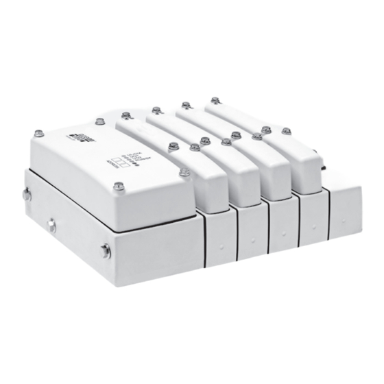
AVENTICS | CL03, CL03-XL | R402000141–BAL–001–AF Gerätebeschreibung Gerätebeschreibung Ventilsystem Abb. 1: Ventilsystem mit Multipolstecker (A) und mit Busmodul (B) 1 Anschlussstück mit 4 Endplatte Multipolstecker 5 Ventilabdeckung 2 Anschlussstück mit 6 Multipolstecker-Abdeckung integriertem Buskoppler 7 Buskoppler-Abdeckung 3 1 bis 16 Anschlussplatten 8 Vorsteuerluft-Abdeckung für Ventile oder Blindplatten... -
Page 12: Ventile Und Anschlussplatten
AVENTICS | CL03, CL03-XL | R402000141–BAL–001–AF Gerätebeschreibung Je nach Konfiguration müssen Sie ihr Ventilsystem entweder über einen Multipolstecker oder über einen Buskoppler, Serie CL03 anschließen (siehe Abb. 1). Die Ausführung mit Multipolstecker ist in der Abbildung mit (A) gekennzeichnet. Bei Ausführungen mit Buskoppler ist dieser in das Ventilsystem integriert (B), um die Schutzart IP69K zu gewährleisten. - Page 13 Gerätebeschreibung Um die Schutzart IP69K zu gewährleisten, sind die Ventile (9) mit Ventilabdeckungen (5) geschützt. Das Ventilsystem Serie CL03/CL03-XL können Sie mit bis zu 16 Wegeventilen ausrüsten. Je nach Konfiguration können in Ihrem Ventilsystem unterschiedliche Ventile und Anschlussplatten (3) verbaut sein. Sie können das Ventilsystem nachträglich erweitern oder umbauen.
-
Page 14: Montage
Spule gerade angesteuert ist. Die Ventilzuordnungen sind durch die Zahlen 14 und 12 gekennzeichnet. Montage Die Ventilsysteme Serie CL03 und CL03-XL werden jeweils für eine bestimmte Anwendung konfiguriert und dimensioniert und komplett verschraubt mit allen Komponenten gemäß Ihrer individuellen Konfiguration geliefert. - Page 15 AVENTICS | CL03, CL03-XL | R402000141–BAL–001–AF Montage WARNUNG Gefahr von Personen- oder Sachschäden durch unkontrollierte Bewegungen von Anlagenkomponenten! Der Anschluss von Druckluft während des Einbaus des Ventilsystems kann zu Verletzungen oder Schäden an der Anlage führen. Schalten Sie den relevanten Anlagenteil drucklos, bevor Sie mit Montagearbeiten beginnen.
-
Page 16: Einbaulage
AVENTICS | CL03, CL03-XL | R402000141–BAL–001–AF Montage Einbaulage Das Ventilsystem kann in jeder beliebigen Lage eingebaut werden. Beachten Sie jedoch die folgenden Punkte: Um zu verhindern, dass Kondensat in das Ventil fließt, dürfen Sie das System nicht mit der Anschlussseite nach oben einzubauen. - Page 17 F = 57,25 mm + (M x 30 mm) + (N x 36 mm) F = 57,25 mm + (M x 30 mm) + (N x 36 mm) M = Anzahl M x Grundplatte CL03; N = Anzahl M x Grundplatte CL03-XL Befestigung auf Anschlussplatte mit 4 Steckanschlüssen...
- Page 18 F = 2.25 inch (M x 1.18 inch) + (N x 1.42 inch) F = 2.25 inch (M x 1.18 inch) + (N x 1.42 inch) M = Anzahl M x Grundplatte CL03; N = Anzahl M x Grundplatte CL03-XL Befestigung auf Anschlussplatte mit 4 Steckanschlüssen...
-
Page 19: Mecproof-Montage
AVENTICS | CL03, CL03-XL | R402000141–BAL–001–AF Montage 2. Montieren Sie das gesamte Ventilsystem mit Hilfe der Gewindebohrungen (1) auf einer Montagefläche. Die Gewindebohrungen sind am Anschlussstück und in der Endplatte sowie bei allen Anschlussplatten mit 4 Anschlüssen bzw. bei allen Anschlussplatten mit 5x G1/4 Gewindeanschlüssen vorhanden (d. - Page 20 AVENTICS | CL03, CL03-XL | R402000141–BAL–001–AF Montage Abb. 5: Mecproof-Montage 11 Abdeckrahmen 12 Dichtungsleiste Fertigen Sie eine Schablone für die notwendigen Bohrlöcher nach folgenden Maßangaben. 56.9 + N x 29.7 12.1 + N x 29.7 Ø L = 63,5 + M x 30 mm...
-
Page 21: Ventilsystem Erden
AVENTICS | CL03, CL03-XL | R402000141–BAL–001–AF Montage Befestigen Sie das Ventilsystem mit dem Abdeckrahmen und der Dichtungsleiste wie in Abb. 5 dargestellt. (Befestigungsmaße siehe Abb. 6). Das maximale Anzugsmoment der Befestigungsschrauben beträgt 4 Nm. Die maximale Gewindetiefe ist 15 mm. - Page 22 AVENTICS | CL03, CL03-XL | R402000141–BAL–001–AF Montage Mit Hilfe von Verschlussstopfen können Sie das Ventilsystem in mehrere Druckzonen aufteilen (siehe Kapitel 8.3 „Getrennte Druckzonen einrichten“ auf Seite 45). Abb. 7: Beschriftung der Pneumatikanschlüsse Tabelle 3: Pneumatikanschlüsse metrische max. Bezeichnung Zuluft- und Abluftleitungen zöllige Version...
- Page 23 AVENTICS | CL03, CL03-XL | R402000141–BAL–001–AF Montage Tabelle 3: Pneumatikanschlüsse metrische max. Bezeichnung Zuluft- und Abluftleitungen zöllige Version Version Anzugsmoment [Nm] Vent Entlüftung G 1/8 NPT 1/8 2 und 4 Anschlüsse 2 und 4 G 1/4 – CL03: ∅ 8 2 und 4 Steckanschlüsse 2 und 4...
- Page 24 AVENTICS | CL03, CL03-XL | R402000141–BAL–001–AF Montage – Ein normal geschlossenes 3/2-Wegeventil arbeitet wie ein normal offenes 3/2-Wegeventil. – Bei 5/3- und 5/2-Wegeventilen ist die Spule/LED 14 dem Druckluftanschluss 2 zugeordnet und die Spule/LED 12 ist Druckluftanschluss 4 zugeordnet. Anschluss 1 steht immer am Anschlussstück (1) und an der Endplatte (3) zur Verfügung.
-
Page 25: Ventilsystem Elektrisch Anschließen
AVENTICS | CL03, CL03-XL | R402000141–BAL–001–AF Montage VORSICHT Gefahr von Schäden am Ventilsystem! Verschließen Sie niemals Anschluss R! Das Verschließen der Abluftausgänge führt zu Luftstau und einer Beschädigung der Ventile. Sorgen Sie für ausreichende Entlüftung über den Abluftanschluss und Anschluss R. - Page 26 AVENTICS | CL03, CL03-XL | R402000141–BAL–001–AF Montage Schließen Sie bei beidseitig betätigten Ventilen die beiden Spulen 14 und 12 an. Bei 3/2-Wegeventilen gelten dabei folgende Zuordnungen: – Spule 14 und Pneumatikanschluss 4 – Spule 12 und Pneumatikanschluss 2 Bei einer CL03-XL-Anschlussplatte für parallel angesteuerte Ventile wird gleichzeitig die darauffolgende Anschlussplatte mit angesteuert.
- Page 27 AVENTICS | CL03, CL03-XL | R402000141–BAL–001–AF Montage Abb. 8: Anschlusspinzuordnung bei bis zu 16 Ventilen/32 Spulen Tabelle 4: Ventilplatz Spule/LED...
- Page 28 AVENTICS | CL03, CL03-XL | R402000141–BAL–001–AF Montage Tabelle 4: Ventilplatz Spule/LED Abb. 9: Anschlusspinzuordnung bei bis zu 8 Ventilen/16 Spulen Tabelle 5: Ventilplatz Spule/LED...
-
Page 29: Multipolstecker Montieren
AVENTICS | CL03, CL03-XL | R402000141–BAL–001–AF Montage Tabelle 5: Ventilplatz Spule/LED Multipolstecker montieren 1. Vergewissern Sie sich, ob die Dichtung in die Nut eingelegt ist. 2. Setzen Sie dann den Stecker fest ein. 3. Befestigen Sie die Multipolstecker-Abdeckung mit den vier Sechskantschrauben. -
Page 30: Inbetriebnahme
AVENTICS | CL03, CL03-XL | R402000141–BAL–001–AF Inbetriebnahme Inbetriebnahme Die Inbetriebnahme darf nur von einer Elektro- oder Pneumatikfachkraft oder von einer unterwiesenen Person unter der Leitung und Aufsicht einer Fachkraft erfolgen (siehe auch „Qualifikation des Personals“ auf Seite 5). Funktion der Ventile überprüfen Die Funktionsfähigkeit und Betriebsart der Ventile können Sie... - Page 31 AVENTICS | CL03, CL03-XL | R402000141–BAL–001–AF Inbetriebnahme max. 3 mm Abb. 10: Korrekte Bedienung der Handhilfsbetätigung 6.1.1 Drehen und rasten (gelber Knopf): Setzen Sie einen Schraubendreher in die Nut der Handhilfsbetätigung (13) und drehen Sie mit geringer Kraft von Position 0 auf Position 1, bis sie mit einem leichten Klick rastet (siehe Abb.
-
Page 32: Mit Spannung Und Druckluft Beaufschlagen
AVENTICS | CL03, CL03-XL | R402000141–BAL–001–AF Inbetriebnahme Mit Spannung und Druckluft beaufschlagen WARNUNG Unkontrollierte Bewegungen aufgrund fehlerhaft angeschlossener Druckluftleitungen am Ventilsystem! Fehlerhafte Montage von Druckluftleitungen mit Steckverbindungen kann dazu führen, dass sich diese nach Beaufschlagung des Ventilsystems mit Druckluft lösen und Verletzungen oder Schäden am Gerät verursachen. -
Page 33: Demontage Und Austausch
AVENTICS | CL03, CL03-XL | R402000141–BAL–001–AF Demontage und Austausch Demontage und Austausch Anweisungen zum Entfernen der Ventilabdeckungen finden Sie im Kapitel „Reserveventilplätze belegen“ auf Seite 34. Anweisungen zum Einrichten von getrennten Druckzonen finden Sie im Kapitel „Getrennte Druckzonen einrichten“ auf Seite 41. -
Page 34: Ventilsystem Austauschen
Ventilsystem montieren (siehe „Montage” auf Seite 12). Umbau und Erweiterung VORSICHT Gefahr von Schäden am Ventilsystem! Zu hoher Druck am Abluftanschluss kann die Einheit beschädigen. Beaufschlagen Sie den Anschluss „Vent“ mit maximal 0,7 bar (bei CL03) bzw. maximal 0,3 bar (bei CL03-XL). - Page 35 AVENTICS | CL03, CL03-XL | R402000141–BAL–001–AF Umbau und Erweiterung ACHTUNG Ziehen von Steckern unter Spannung zerstört das Gerät! Beim Ziehen von Steckern unter Spannung entstehen große Potenzialunterschiede, die das Gerät zerstören können. Schalten Sie den relevanten Anlagenteil spannungsfrei, bevor Sie das Gerät demontieren.
-
Page 36: Reserveventilplätze Belegen
AVENTICS | CL03, CL03-XL | R402000141–BAL–001–AF Umbau und Erweiterung Reserveventilplätze belegen Um Reserveventilplätze zu belegen, müssen Sie die Blindplatte entfernen und ein neues Ventil auf die Anschlussplatte montieren. Voraussetzung Sie haben das Ventilsystem drucklos und spannungsfrei geschaltet. 8.1.1 Blindplatte entfernen 1. -
Page 37: Ventil Einsetzen
AVENTICS | CL03, CL03-XL | R402000141–BAL–001–AF Umbau und Erweiterung 8.1.2 Ventil einsetzen 1. Setzen Sie das neue Ventil (5) auf die freie Anschlussplatte auf. Achten Sie darauf, dass die Kontakte gerade sind und die Dichtung (18) korrekt sitzt. Drücken Sie mit geringer Kraft auf das Ventilende mit dem elektrischen Anschluss, bis der elektrische Kontakt hergestellt ist. - Page 38 Anschlussplatte für parallel angesteuerte Ventile verwenden. – Bei 18 Ventilplätzen müssen Sie mindestens zwei Anschlussplatten für parallel angesteuerte Ventile verwenden. Die Dichtungen (5) für das CL03 und das CL03-XL sind identisch. 8.2.2 Ventilsystem demontieren 1. Schalten Sie den relevanten Anlagenteil drucklos und spannungsfrei.
- Page 39 SW 8. 8.2.4 Anschlussplatten einbauen Um Anschlussplatten einzubauen, benötigen Sie je nach Anzahl der Ventile die entsprechende Anzahl an Zugankererweiterungen, bestehend aus je drei Zugankern und drei Zugankermuttern. Zugankererweiterungen für die Ventilsysteme CL03 und CL03-XL finden Sie im Online-Katalog (www.aventics.com/pneumatics-catalog).
- Page 40 AVENTICS | CL03, CL03-XL | R402000141–BAL–001–AF Umbau und Erweiterung Abb. 12: Anschlussplatte einbauen 1. Drehen Sie die drei Zuganker (21) aus dem Zugankerbausatz ca. 10 mm weit in die Zugankermuttern (22) ein. 2. Überprüfen Sie. ob die Dichtung (23) auf der Anschlussplatte des Ventilsystems korrekt sitzt.
- Page 41 AVENTICS | CL03, CL03-XL | R402000141–BAL–001–AF Umbau und Erweiterung 8.2.5 Endplatte wieder montieren Abb. 13: Endplatte montieren 1. Setzen Sie die Endplatte wieder auf. Achten Sie dabei auf korrekte Lage der Dichtung. Ziehen Sie die drei Sechskantschrauben (20) an. Anzugsmoment: 2,8–3,2 Nm 2.
- Page 42 AVENTICS | CL03, CL03-XL | R402000141–BAL–001–AF Umbau und Erweiterung 8.2.6 Ventil oder Blindplatte montieren Abb. 14: Ventile oder Blindplatte aufsetzen 1. Setzen Sie das Ventil (17) bzw. die Blindplatte (16) auf die neue Anschlussplatte. Achten Sie darauf, dass die Kontakte gerade sind und die Dichtung (18) korrekt sitzt.
-
Page 43: Getrennte Druckzonen Einrichten
AVENTICS | CL03, CL03-XL | R402000141–BAL–001–AF Umbau und Erweiterung 4. Setzen Sie die Ventilabdeckung (5) wieder auf. Achten Sie dabei auf die korrekte Lage der Dichtung (19). Ziehen Sie die drei Sechskantschrauben (14) an. Anzugsmoment: 1,0–1,2 Nm 8.2.7 Anschlüsse wieder herstellen 1. -
Page 44: Interne Und Externe Vorsteuerluft Einstellen
AVENTICS | CL03, CL03-XL | R402000141–BAL–001–AF Umbau und Erweiterung Abb. 15: Einsetzen von Verschlussstopfen zum Einrichten von getrennten Druckzonen. 3. Bauen Sie das Ventilsystem gemäß den Anweisungen im Kapitel „Ventilsystem auf einer Montagefläche montieren“ auf Seite 14 wieder zusammen. Interne und externe Vorsteuerluft einstellen Je nach Konfiguration wird das Ventilsystem intern oder extern mit Vorsteuerluft versorgt. - Page 45 AVENTICS | CL03, CL03-XL | R402000141–BAL–001–AF Umbau und Erweiterung Für die Vorsteuerluftversorgung stehen drei Alternativen zur Auswahl (siehe Abb.16): Interne Versorgung der Vorsteuerventile durch Kanal 1. Der Markierungspunkt (4) befindet sich hierbei in Position 1-X. Interne Versorgung der Vorsteuerventile durch Kanal 5.
- Page 46 AVENTICS | CL03, CL03-XL | R402000141–BAL–001–AF Umbau und Erweiterung Schließen Sie die Vorsteuerluftversorgung am Anschluss X auf der Unterseite der Endplatte an. Stellen Sie sicher, dass der externe Vorsteuerdruck innerhalb der Grenzen liegt, die im Kapitel „Technische Daten“ auf Seite 49 angegeben sind.
-
Page 47: Ip69K-Schutz Und Dichtungen Überprüfen
Zu hoher Druck beim Anschließen von Druckluft an den Abluftanschluss kann die Einheit beschädigen. Beaufschlagen Sie den Anschluss „Vent“ mit maximal 0,7 bar (bei CL03) bzw. 0,3 bar (bei CL03-XL). Um den IP69K-Schutz nach einer Modifikation sicherzustellen: Überprüfen Sie den korrekten Sitz aller Dichtungen in den Dichtungsnuten. -
Page 48: Wartung Und Pflege
Zeit einwirken. Halten Sie auf jeden Fall die Bedingungen für die jeweilige Schutzart der Einheit ein. Die Ventilsysteme CL03 und CL03-XL sind für den Einsatz in Nassbereichen konzipiert. Nach korrekter Montage können sie daher unter hohem Druck und bei hohen Temperaturen (IP69K-Bedingungen) gereinigt werden. -
Page 49: Wenn Störungen Auftreten
AVENTICS | CL03, CL03-XL | R402000141–BAL–001–AF Wenn Störungen auftreten 11 Wenn Störungen auftreten Informationen zur Fehlerbehebung finden Sie im Kapitel „Test und Diagnose“ des Handbuchs zum jeweiligen Buskoppler. Informationen zum Austausch eines defekten Ventilsystems finden Sie im Kapitel „Demontage und Austausch“ auf Seite 31. -
Page 50: Störungstabelle
In Tabelle 6 finden Sie eine Übersicht über Störungen, mögliche Ursachen und deren Abhilfe. Falls Sie den aufgetretenen Fehler nicht beheben konnten, wenden Sie sich an die AVENTICS GmbH. Die Adresse finden Sie auf der Rückseite der Anleitung. Tabelle 6: Störung... -
Page 51: Technische Daten
AVENTICS | CL03, CL03-XL | R402000141–BAL–001–AF Technische Daten 12 Technische Daten Table 7 Technische Daten Allgemeine Daten Ventiltyp Schieberventil, weich dichtend Abmessungen konfigurationsabhängig (siehe Abb. 3 auf Seite 15 und Abb. 4. auf Seite 16) Gewicht konfigurationsabhängig (siehe Konfigurator) Temperaturbereich für Anwendung 0 °C bis +50 °C ohne Betauung... -
Page 52: Stichwortverzeichnis
AVENTICS | CL03, CL03-XL | R402000141–BAL–001–AF Stichwortverzeichnis 13 Stichwortverzeichnis Abfallentsorgung 8 Handhilfsbetätigung 12, Abkürzungen 4 28, 29, 35, 40 Abmessungen 14, 15, 49 Anschluss R 19, 23 Anschluss X 22, 43, 44 Inbetriebnahme 5, 7, 28 Austausch 31, 47 Konfiguration 7, 8, 12, 14,... - Page 53 AVENTICS | CL03, CL03-XL | R402000141–BAL–001–AF Stichwortverzeichnis Sicherheit 4 Steuerdruck 49 Störungen 3, 47 Störungstabelle 48 Technische Daten 49 Umbau 32 Vent, Anschluss 19, 21, 45 Ventilsteuerung 28 Verschlussstopfen 21, 33, 41, 42 Vorsteuerluftversorgung 22, 31, 42, 43, 44 Warnhinweise 4, 6...
- Page 55 AVENTICS | CL03, CL03-XL | R402000141–BAL–001–AF Contents Contents About This Document ..........55 Related documents ..............55 Abbreviations................56 For Your Safety ............56 Intended use................56 Improper use ................57 Personnel qualifications............57 Warnings ..................58 The following must be observed: ........58 Delivery Contents ............60 Device Description ............
- Page 56 AVENTICS | CL03, CL03-XL | R402000141–BAL–001–AF Contents Maintenance and Care ..........96 10.1 Maintaining the valve system ..........96 10.2 Cleaning and servicing the valve system......97 If Malfunctions Occur ..........98 11.1 Proceed as follows for troubleshooting ......98 11.2 Table of malfunctions ............99 Technical Data ............
-
Page 57: About This Document
About This Document These instructions contain important information on the safe and appropriate assembly, operation, and maintenance of the CL03 and CL03-XL valve systems and how to remedy simple malfunctions yourself. Read this documentation completely, especially chapter “For Your Safety” on page 56, before working with your valve system. -
Page 58: Abbreviations
CL03 Clean Line For Your Safety The CL03 and CL03-XL valve systems have been manufactured according to the accepted rules of safety and current technology. There is, however, still a danger of personal injury or damage to equipment if the following general safety instructions and the warnings before the steps contained in these instructions are not complied with. -
Page 59: Improper Use
AVENTICS | CL03, CL03-XL | R402000141–BAL–001–AF For Your Safety Only use the Valve system within the performance range provided in the technical data. The Valve system is only intended for industrial applications. Intended use includes having read and understood these instructions, especially the chapter “For Your Safety”. -
Page 60: Warnings
AVENTICS | CL03, CL03-XL | R402000141–BAL–001–AF For Your Safety Warnings In this document, there are safety instructions before the steps whenever there is a danger of personal injury or damage to the equipment. The measures described to avoid these hazards must be followed. - Page 61 AVENTICS | CL03, CL03-XL | R402000141–BAL–001–AF For Your Safety Always make sure the relevant system component is not under pressure or voltage before carrying out work on the valve system. Ensure the system cannot be switched on accidentally during work.
-
Page 62: Delivery Contents
A Valve system according to configuration and order Valve system operating instructions If you operate your valve system with a bus coupler from the CL03 series, the following is additionally included in the scope of delivery: Operating instructions for the bus coupler... -
Page 63: Device Description
AVENTICS | CL03, CL03-XL | R402000141–BAL–001–AF Device Description Device Description Valve system Fig. 1: Valve system with multipole plug (A) and with bus module (B) 1 Connection piece with 4 End plate multipole plug 5 Valve cover 2 Connection piece with... -
Page 64: Valves And Subbases
AVENTICS | CL03, CL03-XL | R402000141–BAL–001–AF Device Description Your valve system must either be connected via a CL03 series bus coupler or a multipole plug depending on the configuration (see Fig. 1). The version with multipole plug is labeled in the figure with (A). - Page 65 There are two windows (5) in the valve covers where the state of the LEDs (10) can be checked. CL03-XL With a CL03-XL subbase for parallel control of the valves, with 18 valve positions the next subbase will also be controlled at the same time.
-
Page 66: Manual Override
Valve assignments are indicated by the numbers 14 and 12. Assembly The CL03 and CL03-XL series valve systems are configured and dimensioned for a specific application and delivered completely fitted with all components according to an individual configuration. -
Page 67: Mounting Orientation
AVENTICS | CL03, CL03-XL | R402000141–BAL–001–AF Assembly WARNING Risk of injury or damage due to uncontrolled movement of system components! Connection of compressed air while the valve system is being installed may lead to physical injury or system damage. Make sure that the relevant part of the system is not under pressure during installation. -
Page 68: Assembling The Valve System On The Mounting Surface
AVENTICS | CL03, CL03-XL | R402000141–BAL–001–AF Assembly Assembling the valve system on the mounting surface CAUTION Risk of damage to the valve system! Too long or too short screws, or too high torque, may damage the threaded mounting holes. To ensure correct assembly, use the correct screw length and torque as follows: –... - Page 69 F = 57.25 mm + (M x 30 mm) + (N x 36 mm) F = 57.25 mm + (M x 30 mm) + (N x 36 mm) M = number M x CL03 base plate; N = number M x CL03-XL base plate Mounting to subbase with 4 push-in fittings...
- Page 70 F = 2.25 inch (M x 1.18 inch) + (N x 1.42 inch) F = 2.25 inch (M x 1.18 inch) + (N x 1.42 inch) M = number M x CL03 base plate; N = number M x CL03-XL base plate Mounting to subbase with 4 push-in fittings...
-
Page 71: Mecproof Mounting
AVENTICS | CL03, CL03-XL | R402000141–BAL–001–AF Assembly 2. Mount the complete valve system on a mounting surface using the threaded holes (1). The threaded holes are available in the connection piece and in the end plate, as well as in all subbases with four connections or all subbases with 5x G1/4 thread connections (i.e. -
Page 72: Grounding The Valve System
AVENTICS | CL03, CL03-XL | R402000141–BAL–001–AF Assembly Use the following dimensions to make a suitable hole template with screw holes. 56.9 + N x 29.7 12.1 + N x 29.7 Ø L = 63.5 + M x 30 mm (multipole connection) or L = 101.5 + M x 30 mm... -
Page 73: Connecting The Valve System Pneumatics
AVENTICS | CL03, CL03-XL | R402000141–BAL–001–AF Assembly Connecting the valve system pneumatics CAUTION Risk of damage to valves! Pilot control exhaust air connection R must never be closed as this may damage the valves. The exhaust air connection “Vent” in the end plate must not be closed either. - Page 74 AVENTICS | CL03, CL03-XL | R402000141–BAL–001–AF Assembly Fig. 7: Labeling pneumatic connections Table 3: Pneumatic connections Max. tightening Designation Supply and exhaust lines Metric version Inch version torque [Nm] Connection 1 G1/2 NPT 1/2 3 and 5 Connections 3 and 5...
- Page 75 AVENTICS | CL03, CL03-XL | R402000141–BAL–001–AF Assembly Table 3: Pneumatic connections Max. tightening Designation Supply and exhaust lines Metric version Inch version torque [Nm] CL03: ∅ 8 2 and 4 Push-in fittings 2 and 4 CL03_ 5/16" Not applicable or 3/8"...
- Page 76 AVENTICS | CL03, CL03-XL | R402000141–BAL–001–AF Assembly Connection 1 is always available on the connection piece (1) and on the end plate (3). Connections 3 and 5 are always available on the connection piece and may also be present on each individual subbase (2) or end plate (3) depending on how the valve system is configured (see Fig.
-
Page 77: Connecting The Valve System Electrics
– Solenoid 14 and pneumatic connection 4 – Solenoid 12 and pneumatic connection 2 With a CL03-XL subbase for parallel control of the valves, the next subbase will also be controlled at the same time. It is possible to increase the total number of valve positions to 18, but the maximum number of controllable solenoids remains 32. - Page 78 (20 mA per solenoid). All GND pins in the multipole plug are bridged. This must be observed in particular with a CL03-XL subbase for parallel actuation of valves. Protect the solenoid control with an external fuse.
- Page 79 AVENTICS | CL03, CL03-XL | R402000141–BAL–001–AF Assembly Table 4: Valve position Solenoid/ LED...
- Page 80 AVENTICS | CL03, CL03-XL | R402000141–BAL–001–AF Assembly Fig. 9: Connector pin assignment for up to 8 valves/16 solenoids Table 5: Valve position Solenoid/ LED...
-
Page 81: Mounting The Multipole Plug
AVENTICS | CL03, CL03-XL | R402000141–BAL–001–AF Commissioning Mounting the multipole plug 1. Make sure the seal is inserted in the slot. 2. Then place the plug so that connection is secured. 3. Fix the multipole plug cover by fastening the four hexagon screws. - Page 82 AVENTICS | CL03, CL03-XL | R402000141–BAL–001–AF Commissioning max. 3 mm Fig. 10: Operating the manual override correctly 6.1.1 Turn and detent (yellow knob): Insert a screwdriver blade in the slot of the manual override (13) and turn it from position 0 to position 1 using slight force until it clicks into place (see Fig.
-
Page 83: Applying Voltage And Compressed Air
AVENTICS | CL03, CL03-XL | R402000141–BAL–001–AF Commissioning Applying voltage and compressed air WARNING Uncontrolled movements due to incorrectly connected compressed air lines in the valve system! Incorrectly assembled compressed air lines with plug connections could come loose when pressure is applied to the valve system, resulting in injuries or damage to the device. -
Page 84: Disassembly And Exchange
AVENTICS | CL03, CL03-XL | R402000141–BAL–001–AF Disassembly and Exchange Disassembly and Exchange For instructions on removing valve covers, see section “Assigning reserve valve positions” on page 85. For instructions on creating separate pressure zones, see section “Creating separate pressure zones” on page 92. -
Page 85: Exchanging The Valve System
AVENTICS | CL03, CL03-XL | R402000141–BAL–001–AF Disassembly and Exchange Exchanging the valve system In order to exchange the valve system, disassemble it first as described above and then mount the new valve system (see “Assembly” on page 64). -
Page 86: Conversion And Extension
Risk of damage to the valve system! Too high pressure on the exhaust air connection may damage the unit. Do not exceed 0.7 bar (for CL03) or 0.3 bar (for CL03-XL) when connecting compressed air to the "Vent" connection. NOTICE... -
Page 87: Assigning Reserve Valve Positions
AVENTICS | CL03, CL03-XL | R402000141–BAL–001–AF Conversion and Extension The following conversions and extensions can be made to the valve system: Assigning reserve valve positions (see page 85) Adding further valve positions (see page 87) Creating separate pressure zones by closing the air... -
Page 88: Inserting A Valve
AVENTICS | CL03, CL03-XL | R402000141–BAL–001–AF Conversion and Extension 8.1.2 Inserting a valve 1. Place the new valve (5) on the free subbase. Make sure the contacts are straight and that the seal (18) is seated correctly. Press gently on the valve's electrical connector end until the electrical contact is made. -
Page 89: Adding Additional Valve Positions
– For 18 valve positions, at least two subbases must be used for parallel actuation of valves. The seals (5) for CL03 and CL03-XL are identical. 8.2.2 Disassembling the valve system 1. Make sure the relevant system part is not under voltage or pressure. -
Page 90: Removing The End Plate
In order to install subbases, the corresponding number of tie rod extensions, consisting of three tie rods and three tie rod nuts, are required depending on the number of valves. Tie rod extensions for valve systems CL03 and CL03-XL can be found in the online catalog (www.aventics.com/pneumatics-catalog). - Page 91 AVENTICS | CL03, CL03-XL | R402000141–BAL–001–AF Conversion and Extension Fig. 12: Installing the subbase 1. Screw the three tie rod extensions (21), supplied in the tie rod extension kit, approximately 10 mm into the tie rod nuts (22). 2. Check whether the seal (23) is seated correctly on the valve system subbase.
- Page 92 AVENTICS | CL03, CL03-XL | R402000141–BAL–001–AF Conversion and Extension 8.2.5 Remounting the end plate Fig. 13: Assembling the end plate 1. Replace the end plate. Making sure the seal is in the correct position. Tighten the three hexagon screws (20).
- Page 93 AVENTICS | CL03, CL03-XL | R402000141–BAL–001–AF Conversion and Extension 8.2.6 Mounting the valve or blanking plate Fig. 14: Installing the valves or blanking plate 1. Place the valve (17) or the blanking plate (16) on the new subbase. Make sure the contacts are straight and that the seal (18) is seated correctly.
-
Page 94: Creating Separate Pressure Zones
AVENTICS | CL03, CL03-XL | R402000141–BAL–001–AF Conversion and Extension 4. Replace the valve cover (5). Make sure the seal is in the correct position (19). Tighten the three hexagon screws (14). Tightening torque: 1.0-1.2 Nm 8.2.7 Reestablishing connections 1. Make the pneumatic connections to the new subbase and valve system (see “Connecting the valve system... -
Page 95: Setting The Internal And External Pilot Air
AVENTICS | CL03, CL03-XL | R402000141–BAL–001–AF Conversion and Extension Fig. 15: Inserting blanking plugs to obtain separate pressure zones. 3. Reassemble the valve system according to the instructions in section “Assembling the valve system on the mounting surface” on page 66. - Page 96 AVENTICS | CL03, CL03-XL | R402000141–BAL–001–AF Conversion and Extension Three different options for pilot supply are available (see Fig. 16): Pilots supplied internally through channel 1. The indicator dot (4) will then be in position 1-X. Pilots supplied internally through channel 5. The indicator dot (4) will then be in position 5-X.
-
Page 97: Checking Ip69K Protection And Seals
Risk of damage to the valve system! Too high pressure when connecting compressed air to the exhaust air connection may damage the unit. Do not exceed 0.7 bar (for CL03) or 0.3 bar (for CL03-XL) when connecting compressed air to the "Vent" connection. -
Page 98: Disposal
10 Maintenance and Care 10.1 Maintaining the valve system The CL03 and CL03-XL valve systems are maintenance-free. Comply with the maintenance intervals and instructions for the entire system where the valve system is used, and the instructions below. -
Page 99: Cleaning And Servicing The Valve System
Do not exceed the conditions of the protection class of the unit. The CL03 and CL03-XL valve systems are designed for use in wet zones. After correct assembly, they can be cleaned under high pressure and at high temperatures (IP69K conditions). -
Page 100: If Malfunctions Occur
AVENTICS | CL03, CL03-XL | R402000141–BAL–001–AF If Malfunctions Occur 11 If Malfunctions Occur Refer to the section “Test and diagnosis” in the respective bus coupler manual for information on troubleshooting. See “Disassembly and Exchange” on page 82 for information on how to exchange a faulty valve system. -
Page 101: Table Of Malfunctions
11.2 Table of malfunctions Table 6 contains an overview of malfunctions, possible causes, and remedies. If you cannot remedy a malfunction, please contact AVENTICS GmbH. The address is printed on the back cover of these instructions. Table 6: Malfunction Possible cause... -
Page 102: Technical Data
AVENTICS | CL03, CL03-XL | R402000141–BAL–001–AF Technical Data 12 Technical Data Table 7: Technical data General data Valve type Spool valve, soft seal Dimensions Depends on configuration; (see Fig. 3 on page 67 and Fig. 4. on page 68) Weight... -
Page 103: Index
AVENTICS | CL03, CL03-XL | R402000141–BAL–001–AF Index Index Abbreviations 56 Fieldbus protocols 75 Abmessungen 67 Assembly 57, 59, 64, 65, 66, 81, 97 Hazards 57 Blanking plug 73, 85, 92, Installation 69 Maintenance 59, 96 Cleaning 97 Malfunctions 55, 98... - Page 104 AVENTICS | CL03, CL03-XL | R402000141–BAL–001–AF Index Safety 56 Solvents 59, 97 Switching time 100 Table of malfunctions 99 Technical data 100 Unintended 56, 57 Valve control 79 Vent, connection 71, 72, Warnings 56, 58 Waste disposal 59 X, connection 72, 74, 94...
- Page 105 AVENTICS | CL03, CL03-XL | R402000141–BAL–001–AF Sommaire Sommaire A propos de ce mode d’emploi ........ 105 Documentation supplémentaire ........105 Abréviations ................106 Pour votre sécurité ........... 106 Utilisation conforme ............106 Utilisation non conforme............ 107 Qualification du personel ........... 107 Consignes de danger............
- Page 106 AVENTICS | CL03, CL03-XL | R402000141–BAL–001–AF Sommaire Transformation et extension ........135 Affectation des emplacements de distributeurs de réserve............. 136 Montage d’emplacements de distributeurs supplémentaires..............139 Etablir des zones de pression séparées ....... 144 Régler l'air pilote interne et externe....... 145 Vérifier la protection IP69K et les joints......
-
Page 107: Propos De Ce Mode D'emploi
Ce mode d’emploi contient des informations importantes pour installer, utiliser et entretenir le système de distributeurs série CL03 et CL03-XL de manière sûre et conforme, ainsi que pour pouvoir éliminer soi-même de simples interférences. Lire entièrement cette documentation et en particulier le chapitre «... -
Page 108: Abréviations
CL03 Clean Line Pour votre sécurité Les systèmes de distributeurs CL03 et CL03-XL ont été conçus selon l'état actuel de la technique et conformément aux dispositions applicables en matière de sécurité. Des dommages matériels ou corporels peuvent néanmoins survenir si les consignes de sécurité... -
Page 109: Utilisation Non Conforme
AVENTICS | CL03, CL03-XL | R402000141–BAL–001–AF Pour votre sécurité Utiliser les Ilot de distribution uniquement dans le domaine d'application indiqué dans les données techniques. Employer le Ilot de distribution uniquement dans le domaine industriel. L'utilisation conforme inclut le fait d’avoir lu et compris ce mode d’emploi et en particulier le chapitre «... -
Page 110: Consignes De Danger
AVENTICS | CL03, CL03-XL | R402000141–BAL–001–AF Pour votre sécurité Consignes de danger Dans les présentes instructions, toute consigne dont l’exécution est susceptible d’entraîner des dommages corporels ou matériels est précédée d’un avertissement. Les mesures décrites pour éviter des dangers doivent être respectées. - Page 111 AVENTICS | CL03, CL03-XL | R402000141–BAL–001–AF Pour votre sécurité Ne surcharger en aucun cas l’appareil de manière mécanique. Ne jamais y déposer d’objets. Toujours mettre la partie concernée de l’installation hors tension et hors pression, avant d’effectuer des travaux sur le système de distributeurs.
-
Page 112: Fourniture
Si le système de distributeurs est utilisé avec un coupleur de bus de la série CL03, la fourniture comprend également : mode d'emploi du coupleur de bus Le système de distributeurs est configuré individuellement par AVENTICS à... -
Page 113: Description De L'appareil
AVENTICS | CL03, CL03-XL | R402000141–BAL–001–AF Description de l’appareil Description de l’appareil Ilot de distribution Fig. 1: Système de distributeurs avec connecteur multipôle (A) et module bus (B) 1 Pièce de raccordement avec 4 Plaque terminale connecteur multipôle 5 Couvercle de distributeur 2 Pièce de raccordement avec... -
Page 114: Distributeurs Et Embases
AVENTICS | CL03, CL03-XL | R402000141–BAL–001–AF Description de l’appareil Selon la configuration, le système de distributeurs doit être raccordé via un connecteur multipôle ou un coupleur de bus, série CL03 (voir fig. 1). La version avec connecteur multipôle est marquée d'un (A) sur la figure. - Page 115 Description de l’appareil Pour garantir l'indice de protection IP69K, les distributeurs (9) sont protégés par des couvercles (5). La Système de distributeurs série CL03/CL03-XL peut être équipée avec jusqu'à 16 distributeurs. Selon la configuration, différents distributeurs et embases peuvent être montés dans le système de distributeurs (3).
-
Page 116: Commande Manuelle
Les assignations de distributeurs sont caractérisées par les nombres 14 et 12. Montage Les systèmes de distributeurs série CL03 et CL03-XL sont configurés et dimensionnés pour une application précise et sont livrés entièrement vissés avec tous les composants, conformément à votre configuration individuelle. - Page 117 AVENTICS | CL03, CL03-XL | R402000141–BAL–001–AF Montage AVERTISSEMENT Risque de dommages corporels ou matériels dus à des mouvements incontrôlés de composants de l'installation ! Le raccordement d’air comprimé pendant le montage du système de distributeurs peut provoquer des blessures ou endommager l’installation.
-
Page 118: Position De Montage
AVENTICS | CL03, CL03-XL | R402000141–BAL–001–AF Montage Position de montage Le système de distributeurs peut être monté dans n’importe quelle position. Tenir compte des points suivants : Pour éviter l'écoulement du condensat dans le distributeur, le système ne doit pas être monté avec le côté... - Page 119 F = 57,25 mm + (M x 30 mm) + (N x 36 mm) F = 57,25 mm + (M x 30 mm) + (N x 36 mm) M = Nombre M x Embase CL03 ; N = Nombre M x Embase CL03-XL Fixation sur embase avec 4 raccords instantanés...
- Page 120 F = 2.25 pouces (M x 1.18 pouce) + (N x 1.42 pouce) F = 2.25 pouces (M x 1.18 pouce) + (N x 1.42 pouce) M = Nombre M x Embase CL03 ; N = Nombre M x Embase CL03-XL Fixation sur embase avec 4 raccords instantanés...
-
Page 121: Montage Mecproof
AVENTICS | CL03, CL03-XL | R402000141–BAL–001–AF Montage 2. Monter le système de distributeurs complet à l'aide des trous filetés (1) sur une surface de montage. Les trous filetés sont présents sur la pièce de raccordement, dans la plaque terminale ainsi que sur toutes les embases avec 4 raccords ou sur toutes les embases équipées de 5 raccords filetés G1/4 (c’est-à-dire sur les... - Page 122 AVENTICS | CL03, CL03-XL | R402000141–BAL–001–AF Montage Fig. 5: Montage Mecproof 11 Cadre de recouvrement 12 Barre d’étanchéité Réaliser un gabarit pour les alésages nécessaires selon les dimensions indiquées ci-après. 56.9 + N x 29.7 12.1 + N x 29.7 Ø...
-
Page 123: Mise À La Terre Du Système De Distributeurs
AVENTICS | CL03, CL03-XL | R402000141–BAL–001–AF Montage Fixer le système de distributeurs avec le cadre de recouvrement et la barre d'étanchéité comme illustré à la fig. 5. (dimensions de fixation voir fig. 6). Le couple de serrage maximal des vis de serrage s’élève à... - Page 124 Raccords 3 et 5 CL03 : G 3/8 CL03 : NPT 3/8 CL03 : 6 CL03-XL : G 1/2 CL03-XL : NPT 1/2 CL03-XL : 10 (uniquement en cas de plaque terminale à droite) 3 et 5 Raccords 3 et 5 (embases) G 1/4 –...
-
Page 125: Pression D'alimentation Et Échappement
G 1/8 NPT 1/8 2 et 4 Orifices 2 et 4 G 1/4 – Raccords instantanés 2 et 4 CL03 : ∅ 8 2 et 4 CL03_ 5/16" Mention inutile ou 3/8" CL03-XL : ∅ 10 CL03-XL : – ∅ 10 Raccord instantané... - Page 126 AVENTICS | CL03, CL03-XL | R402000141–BAL–001–AF Montage Lorsque l'alimentation en pression est assurée via les raccords 3 et 5, les symboles de la fonction de distribution imprimés ne sont pas valables. En revanche, ce qui suit s'applique : – Un distributeur 3/2 ouvert normalement fonctionne comme un distributeur 3/2 fermé...
-
Page 127: Raccordement Électrique Du Système De Distributeurs
AVENTICS | CL03, CL03-XL | R402000141–BAL–001–AF Montage Les distributeurs pilotes sont toujours purgés via le canal R dans la plaque terminale. ATTENTION Risque d'endommagement du système de distributeurs ! Ne jamais obturer le raccord R ! L’obturation des sorties d’échappement entraîne une accumulation d’air et un endommagement des distributeurs. - Page 128 Ce point doit être particulièrement mis en œuvre pour les distributeurs pilotés en parallèle dans le cas d'une embase CL03-XL. Protéger la commande des bobines de manière externe. Ne pas dépasser la charge électrique autorisée de 1 A...
- Page 129 AVENTICS | CL03, CL03-XL | R402000141–BAL–001–AF Montage Fig. 8: Affectation des broches de connexion pour jusqu’à 16 distributeurs / 32 bobines Tableau 4 : Emplacement de Bobine / LED Broche distributeur...
- Page 130 AVENTICS | CL03, CL03-XL | R402000141–BAL–001–AF Montage Tableau 4 : Emplacement de Bobine / LED Broche distributeur Fig. 9: Affectation des broches de connexion pour jusqu’à 8 distributeurs / 16 bobines...
-
Page 131: Montage D'un Connecteur Multipôle
AVENTICS | CL03, CL03-XL | R402000141–BAL–001–AF Montage Tableau 5 : Emplacement de Bobine / LED Broche distributeur Montage d'un connecteur multipôle 1. S'assurer que le joint est positionné dans la rainure. 2. Positionner ensuite le connecteur 3. Fixer le couvercle du connecteur multipôle à l’aide des quatre vis à... -
Page 132: Mise En Service
AVENTICS | CL03, CL03-XL | R402000141–BAL–001–AF Mise en service Mise en service La mise en service ne doit être effectuée que par du personnel spécialisé en électronique ou pneumatique ou par une personne instruite et sous la direction et surveillance d’une personne qualifiée (voir également «... -
Page 133: Rotation Et Crantage (Bouton Jaune)
AVENTICS | CL03, CL03-XL | R402000141–BAL–001–AF Mise en service max. 3 mm Fig. 10: Utilisation correcte de la commande manuelle auxiliaire 6.1.1 Rotation et crantage (bouton jaune) : Placer un tournevis dans la rainure de la commande manuelle auxiliaire (13), puis légèrement tourner en passant de la position 0 à... -
Page 134: Alimentation En Tension Et En Air Comprimé
AVENTICS | CL03, CL03-XL | R402000141–BAL–001–AF Mise en service Alimentation en tension et en air comprimé AVERTISSEMENT Mouvements incontrôlés dus à des conduites pneumatiques raccordées au système de distributeurs de manière erronée Un montage erroné des conduites pneumatiques à l’aide de raccords enfichables peut entraîner le desserrage de ces... -
Page 135: Démontage Et Remplacement
AVENTICS | CL03, CL03-XL | R402000141–BAL–001–AF Démontage et remplacement Démontage et remplacement Pour les directives à suivre afin de retirer les couvercles des distributeurs, se reporter au chapitre « Affectation des emplacements de distributeurs de réserve » page 136. Pour les directives à suivre afin d'aménager des zones de pression séparées, se reporter au chapitre «... -
Page 136: Remplacement Du Système De Distributeurs
AVENTICS | CL03, CL03-XL | R402000141–BAL–001–AF Démontage et remplacement Version avec coupleur de bus : débrancher tous les raccordements électriques du coupleur de bus. 2. Débrancher tous les raccordements pneumatiques sur la face inférieure du système de distributeurs. 3. Retirer le système de distributeurs de la surface de montage. -
Page 137: Transformation Et Extension
Une pression trop élevée au niveau du raccord d’échappement peut endommager l’unité. Alimenter le raccord « Distr. » avec maximum 0,7 bar (pour CL03) et 0,3 bar (pour CL03-XL). ATTENTION Le fait de débrancher des connecteurs sous tension peut détériorer l’appareil ! Le débranchement de connecteurs sous tension engendre... -
Page 138: Affectation Des Emplacements De Distributeurs De Réserve
AVENTICS | CL03, CL03-XL | R402000141–BAL–001–AF Transformation et extension Après une transformation du système de distributeurs, noter que la référence se rapporte toujours à la configuration d'origine. Les modifications apportées au système de distributeurs doivent être soigneusement consignées dans la documentation technique. -
Page 139: Retrait De La Plaque D'obturation
AVENTICS | CL03, CL03-XL | R402000141–BAL–001–AF Transformation et extension 8.1.1 Retrait de la plaque d'obturation 1. Retirer les couvercles des distributeurs (5) d'un emplacement de réserve. Pour cela, dévisser trois vis à six pans (14) à l'aide d'un tournevis de 7. -
Page 140: Ajout De Distributeur
AVENTICS | CL03, CL03-XL | R402000141–BAL–001–AF Transformation et extension 8.1.2 Ajout de distributeur 1. Poser le nouveau distributeur (5) sur l’embase libre. Les contacts doivent être droits et le joint (18) bien en place. Appuyer légèrement sur l’extrémité du distributeur avec le raccord électrique jusqu'à... -
Page 141: Montage D'emplacements De Distributeurs Supplémentaires
Le nombre maximal d'embases pour les distributeurs pilotés en parallèle est de deux emplacements de distributeurs par systèmes de distributeurs. Pour le système de distributeurs CL03, le nombre maximal de 16 emplacements de distributeurs ne doit pas être dépassé. Pour le système de distributeurs CL03-XL, le nombre maximal de 18 emplacements de distributeurs ne doit pas être dépassé. - Page 142 Pour monter des embases, le nombre d'extensions à tirant, composées chacune de trois tirants et de trois écrous pour tirants, doit être adapté au nombre de distributeurs. Des extensions à tirant pour les systèmes de distributeurs CL03 et CL03-XL sont proposées dans le catalogue en ligne (www.aventics.com/pneumatics-catalog).
- Page 143 AVENTICS | CL03, CL03-XL | R402000141–BAL–001–AF Transformation et extension Fig. 12: Montage d'une embase 1. Visser les trois tirants (21) du jeu de montage de tirants sur env. 10 mm dans les écrous pour tirants (22). 2. Vérifier que le joint (23) est correctement positionné sur l'embase du système de distributeurs.
- Page 144 AVENTICS | CL03, CL03-XL | R402000141–BAL–001–AF Transformation et extension 8.2.5 Remonter la plaque terminale Fig. 13: Monter la plaque terminale 1. Poser à nouveau la plaque terminale. Veiller au bon positionnement du joint. Visser les trois vis à six pans (20).
-
Page 145: Montage D'un Distributeur Ou D'une Plaque D'obturation
AVENTICS | CL03, CL03-XL | R402000141–BAL–001–AF Transformation et extension 8.2.6 Montage d'un distributeur ou d'une plaque d'obturation Fig. 14: Pose d'un distributeur ou d'une plaque d'obturation 1. Poser le distributeur (17) ou la plaque d’obturation (16) sur la nouvelle embase. Les contacts doivent être droits et le joint (18) bien en place. -
Page 146: Rétablir Les Raccordements
AVENTICS | CL03, CL03-XL | R402000141–BAL–001–AF Transformation et extension 3. Tourner la commande manuelle sur tous les distributeurs en position 0 à l'aide d'un tournevis. 4. Remonter le couvercle de distributeur (5). Veiller au bon positionnement du joint (19). Visser les trois vis à six pans (14). -
Page 147: Régler L'air Pilote Interne Et Externe
AVENTICS | CL03, CL03-XL | R402000141–BAL–001–AF Transformation et extension Fig. 15: Insérer des bouchons d’obturation pour établir des zones de pression séparées. 3. Rétablir le système de distributeurs conformément aux instructions du chapitre « Montage du système de distributeurs sur une surface de montage » page 116. -
Page 148: Régler L'air Pilote Interne
AVENTICS | CL03, CL03-XL | R402000141–BAL–001–AF Transformation et extension Trois possibilités sont disponibles pour l’alimentation en air pilote (voir Fig.16) : Alimentation interne des distributeurs pilotes via le canal 1. Le point de marquage (4) se trouve alors en position 1-X. -
Page 149: Modification De L'alimentation En Air Pilote
AVENTICS | CL03, CL03-XL | R402000141–BAL–001–AF Transformation et extension S'assurer que la pression pilote externe est comprise dans les limites définies au chapitre « Données techniques » page 152. 8.4.3 Modification de l’alimentation en air pilote Fig. 16: Alimentation en air pilote 1. -
Page 150: Vérifier La Protection Ip69K Et Les Joints
Eliminer l’appareil selon les directives du pays d’utilisation. 10 Entretien et maintenance 10.1 Entretien du système de distributeurs Les systèmes de distributeurs CL03 et CL03-XL ne nécessitent aucun entretien. Respecter toutefois les intervalles de maintenance et les prescriptions de l’installation complète dans laquelle... -
Page 151: Nettoyage Et Maintenance Du Système De Distributeurs
à faible concentration et s’ils n’agissent pas trop longtemps. Pour des informations détaillées, s’adresser aux fournisseurs du solvant ou du détergent et, le cas échéant, à AVENTICS (voir adresse en quatrième de couverture). -
Page 152: En Cas De Défaillances
AVENTICS | CL03, CL03-XL | R402000141–BAL–001–AF En cas de défaillances 11 En cas de défaillances Des informations relatives au dépannage sont disponibles au chapitre « Test et diagnostic » du manuel du coupleur de bus correspondant. Des informations sur le remplacement d'un système de distributeurs défaillant sont disponibles au chapitre... -
Page 153: Tableau Des Défauts
AVENTICS | CL03, CL03-XL | R402000141–BAL–001–AF En cas de défaillances 11.2 Tableau des défauts Le tableau 6 propose un récapitulatif des défauts, des causes possibles et des remèdes. Au cas où le défaut survenu s’avérerait insoluble, s’adresser à AVENTICS GmbH. L’adresse est indiquée au dos de ce mode d’emploi. -
Page 154: Données Techniques
AVENTICS | CL03, CL03-XL | R402000141–BAL–001–AF Données techniques 12 Données techniques Tableau 7 : Données techniques Données générales Type de distributeur Distributeur à tiroir, à étanchéité souple Dimensions selon la configuration (voir Fig. 3 page 117 et Fig. 4. page 118) -
Page 155: Index
AVENTICS | CL03, CL03-XL | R402000141–BAL–001–AF Index Index Abmessungen 117 Elimination des Abréviations 106 déchets 110 Alimentation en air Extension 135 pilote 124, 133, 145, 146, Fourniture 110 Bouchons d’obturation 123, 136, Indice de protection 106, 144, 145 109, 149... - Page 156 AVENTICS | CL03, CL03-XL | R402000141–BAL–001–AF Index Qualification 107 Qualification du personnel 107 R, raccord 121, 123, 125 Raccordement électrique 125 Raccordement X 124, 146 Remède au danger 108 Remplacement 133, 150 Sécurité 106 Solvants 109, 149 Tableau des défauts 151...
- Page 157 AVENTICS | CL03, CL03-XL | R402000141–BAL–001–AF Indice Indice Spiegazione delle istruzioni ........157 Ulteriore documentazione ..........157 Abbreviazioni ................. 158 Per la vostra sicurezza ..........158 Utilizzo a norma..............158 Utilizzo non a norma ............159 Qualifica del personale ............159 Avvertenze di sicurezza .............
- Page 158 AVENTICS | CL03, CL03-XL | R402000141–BAL–001–AF Indice Trasformazione e ampliamento ......186 occupare posti valvola di riserva........188 Montaggio di altri posti valvola ........189 Impostare delle zone di pressione separate....194 Regolare l'aria di pilotaggio interna ed esterna..195 Controllare la protezione IP69K e le guarnizioni..............
-
Page 159: Spiegazione Delle Istruzioni
Le istruzioni contengono informazioni importanti per installare, azionare e sottoporre a manutenzione i sistemi valvole serie CL03 e CL03-XL e per riparare autonomamente piccoli guasti, nel rispetto delle norme e della sicurezza. Leggere questa documentazione in ogni sua parte e in particolare il capitolo "Per la vostra sicurezza"... -
Page 160: Abbreviazioni
CL03 Clean Line Per la vostra sicurezza I sistemi valvole CL03 e CL03-XL sono stati fabbricati in base alla tecnica più attuale ed alle norme di sicurezza tecnica valide. Nonostante ciò esiste il pericolo di lesioni alle persone e danni... -
Page 161: Utilizzo Non A Norma
AVENTICS | CL03, CL03-XL | R402000141–BAL–001–AF Per la vostra sicurezza L’utilizzo a norma comprende anche la lettura e la comprensione di queste istruzioni ed in particolar modo del capitolo “Per la vostra sicurezza”. Utilizzo non a norma Per utilizzo non a norma si intende l’impiego del Sistema valvole al di fuori degli ambiti d’applicazione riportati in queste... -
Page 162: Avvertenze Di Sicurezza
AVENTICS | CL03, CL03-XL | R402000141–BAL–001–AF Per la vostra sicurezza Avvertenze di sicurezza In queste istruzioni le azioni da eseguire sono precedute da avvertenze di sicurezza, se esiste pericolo di danni a cose o lesioni a persone. Le misure descritte per la prevenzione di pericoli devono essere rispettate. - Page 163 AVENTICS | CL03, CL03-XL | R402000141–BAL–001–AF Per la vostra sicurezza Togliere sempre l’alimentazione elettrica e pneumatica della parte rilevante dell’impianto prima di eseguire lavori sul sistema valvole. Durante i lavori proteggere l'impianto da una riaccensione. Impiegare l’apparecchio esclusivamente in ambiente industriale (classe A).
-
Page 164: Fornitura
Sistema valvole come da configurazione e ordinazione 1 istruzioni per l'uso del sistema valvole Se si aziona il sistema valvole con un accoppiatore bus della serie CL03 nella fornitura sono inclusi inoltre: 1 istruzioni d'uso per l'accoppiatore bus un CD... -
Page 165: Descrizione Dell'apparecchio
AVENTICS | CL03, CL03-XL | R402000141–BAL–001–AF Descrizione dell'apparecchio Descrizione dell'apparecchio Sistema valvole Fig. 1: Sistema valvole con connettore multipolare (A) e con modulo bus (B) 1 Elemento di raccordo con 4 Piastra terminale connettore multipolare 5 Copertura valvole 2 Elemento di raccordo con... -
Page 166: Valvole E Piastre Di Collegamento
AVENTICS | CL03, CL03-XL | R402000141–BAL–001–AF Descrizione dell'apparecchio A seconda della configurazione il sistema valvole deve essere collegato tramite un connettore multipolare o un accoppiatore bus, serie CL03 (vedere Fig. 1). L'esecuzione con connettore multipolare è contrassegnata nella figura da una (A). - Page 167 (5) attraverso le quali è possibile controllare lo stato dei LED (10). CL03-XL Con una piastra di collegamento CL03-XL per valvole parallele con 18 posti valvola viene pilotata contemporaneamente anche la piastra successiva. In questo modo è possibile aumentare il numero totale dei posti valvola a 18.
-
Page 168: Montaggio
Le assegnazioni valvole si contraddistinguono tramite i numeri 14 e 12. Montaggio I sistemi valvole serie CL03 e CL03-XL vengono rispettivamente configurati e dimensionati per una determinata applicazione e vengono forniti con tutti i componenti completamente avvitati secondo la configurazione individuale. - Page 169 AVENTICS | CL03, CL03-XL | R402000141–BAL–001–AF Montaggio AVVISO Pericolo di danni a cose o persone dovuto a movimenti incontrollati dei componenti dell'impianto! L'attacco dell’aria compressa durante il montaggio del sistema valvole può provocare lesioni o danni all’impianto. Togliere l’alimentazione pneumatica della parte rilevante dell’impianto prima di iniziare i lavori di montaggio.
-
Page 170: Posizione Di Montaggio
AVENTICS | CL03, CL03-XL | R402000141–BAL–001–AF Montaggio Posizione di montaggio Il sistema valvole può essere montato in qualsiasi posizione. Attenersi però ai seguenti punti: Per impedire che la condensa penetri nella valvola, il sistema non deve essere montato con il lato degli attacchi rivolto verso l'alto. - Page 171 F = 57,25 mm + (M x 30 mm) + (N x 36 mm) M = numero M x piastra base CL03; N = numero M x piastra base CL03-XL Fissaggio sulla piastra di collegamento con 4 raccordi ad innesto...
- Page 172 F = 2.25 inch (M x 1.18 inch) + (N x 1.42 inch) F = 2.25 inch (M x 1.18 inch) + (N x 1.42 inch) M = numero M x piastra base CL03; N = numero M x piastra base CL03-XL Fissaggio sulla piastra di collegamento con 4 raccordi ad innesto...
-
Page 173: Montaggio Mecproof
AVENTICS | CL03, CL03-XL | R402000141–BAL–001–AF Montaggio 2. Montare l'intero sistema valvole per mezzo dei fori filettati (1) su una superficie di montaggio. I fori filettati sono presenti sull’elemento di raccordo e nella piastra terminale così come in tutte le piastre di collegamento con 4 attacchi o con 5x attacchi filettati G1/4 (cioè... -
Page 174: Messa A Terra Del Sistema Valvole
AVENTICS | CL03, CL03-XL | R402000141–BAL–001–AF Montaggio 11 Telaio di copertura 12 Listello di tenuta Fissare una sagoma per i fori necessari secondo le seguenti dimensioni. 56.9 + N x 29.7 12.1 + N x 29.7 Ø L = 63,5 + M x 30 mm... -
Page 175: Collegare Pneumaticamente Il Sistema Valvole
AVENTICS | CL03, CL03-XL | R402000141–BAL–001–AF Montaggio Collegare pneumaticamente il sistema valvole CAUTELA Pericolo di danni alle valvole L'attacco per lo scarico dell'aria R non deve essere mai chiuso, altrimenti la valvola ne potrebbe essere danneggiata. Anche l'attacco di scarico "Valv" nella piastra terminale non deve essere chiuso. - Page 176 NPT 1/2 3 e 5 Attacchi 3 e 5 (solo nella CL03: G 3/8 CL03: NPT 3/8 CL03: 6 CL03-XL: G1/2 CL03-XL: NPT 1/2 CL03-XL: 10 piastra terminale destra) 3 e 5 Attacchi 3 e 5 G 1/4 – (piastre di collegamento) CL03: ∅...
- Page 177 AVENTICS | CL03, CL03-XL | R402000141–BAL–001–AF Montaggio Tabella 3: Attacchi pneumatici Condutture aria Versione Coppia di serraggio Definizione Versione in pollici di alimentazione e di scarico metrica max. [Nm] CL03: ∅ 8 2 e 4 Raccordi ad innesto 2 e 4 CL03_ 5/16"...
- Page 178 AVENTICS | CL03, CL03-XL | R402000141–BAL–001–AF Montaggio – Una valvola 3/2 normalmente chiusa lavora come una valvola 3/2 normalmente aperta. – Nelle valvole 5/3 e 5/2 la bobina/LED 14 è assegnata all’attacco per l’aria compressa 2 e la bobina/LED 12 è...
-
Page 179: Collegamento Elettrico Del Sistema Valvole
AVENTICS | CL03, CL03-XL | R402000141–BAL–001–AF Montaggio CAUTELA Pericolo di danni al sistema valvole! Non chiudere mai il raccordo R. La chiusura delle uscite di scarico porta ad accumulo d'aria e al danneggiamento delle valvole. Garantire un sufficiente scarico d’aria tramite l’attacco di scarico e l’attacco R. - Page 180 Per le valvole 3/2 valgono le seguenti assegnazioni: – bobina 14 e raccordo pneumatico 4 – bobina 12 e raccordo pneumatico 2 Con una piastra di collegamento CL03-XL per valvole parallele viene pilotata contemporaneamente anche la piastra successiva. In questo modo è possibile aumentare il numero totale dei posti valvola a 18.
- Page 181 AVENTICS | CL03, CL03-XL | R402000141–BAL–001–AF Montaggio Fig. 8: Assegnazione di un pin di collegamento con fino a 16 valvole/32 bobine Tabella 4: Posto valvola Bobina/LED...
- Page 182 AVENTICS | CL03, CL03-XL | R402000141–BAL–001–AF Montaggio Tabella 4: Posto valvola Bobina/LED Fig. 9: Assegnazione di un pin di collegamento con fino a 8 valvole/ 16 bobine Tabella 5: Posto valvola Bobina/LED...
-
Page 183: Montare Il Connettore Multipolare
AVENTICS | CL03, CL03-XL | R402000141–BAL–001–AF Montaggio Tabella 5: Posto valvola Bobina/LED Montare il connettore multipolare 1. Accertarsi che la guarnizione sia inserita nella scanalatura. 2. Inserire il connettore fissandolo. 3. Fissare la copertura del connettore multipolare con quattro viti esagonali. -
Page 184: Messa In Funzione
AVENTICS | CL03, CL03-XL | R402000141–BAL–001–AF Messa in funzione Messa in funzione La messa in funzione deve essere eseguita solo da parte di personale specializzato in materia elettrica e pneumatica o da una persona istruita sotto la guida e la sorveglianza di personale qualificato (vedere anche "Qualifica del... - Page 185 AVENTICS | CL03, CL03-XL | R402000141–BAL–001–AF Messa in funzione max. 3 mm Fig. 10: Uso corretto del comando manuale 6.1.1 A rotazione e ritenzione (pulsante giallo): Inserire un cacciavite nella scanalatura dell'azionamento manuale (13) e ruotare dalla posizione 0 alla posizione 1, esercitando una forza minima, fino a sentire un leggero clic (vedere Fig.
-
Page 186: Alimentare Con Tensione E Aria Compressa
AVENTICS | CL03, CL03-XL | R402000141–BAL–001–AF Messa in funzione Alimentare con tensione e aria compressa AVVISO Movimenti incontrollati dovuti a linee di aria compressa non collegate correttamente al sistema valvole. Se le linee dell'aria compressa con raccordi ad innesto non... -
Page 187: Smontaggio E Sostituzione
AVENTICS | CL03, CL03-XL | R402000141–BAL–001–AF Smontaggio e sostituzione Smontaggio e sostituzione Le istruzioni per la rimozione delle coperture valvole sono riportate nel capitolo "occupare posti valvola di riserva" a pagina 188. Le istruzioni per l'impostazione delle zone di pressione separate sono riportate nel capitolo "Impostare delle zone di... -
Page 188: Sostituire Il Sistema Valvole
(vedere "Montaggio" a pagina 166). Trasformazione e ampliamento CAUTELA Pericolo di danni al sistema valvole! Una pressione eccessiva in corrispondenza dell'attacco di scarico può danneggiare l'unità. Alimentare l'attacco “Valv” con massimo 0,7 bar (nella CL03) o massimo 0,3 bar (nella CL03-XL). - Page 189 AVENTICS | CL03, CL03-XL | R402000141–BAL–001–AF Trasformazione e ampliamento ATTENZIONE Scollegando i connettori sotto tensione si distrugge l’apparecchio Scollegando i connettori sotto tensione si verificano grandi differenze di potenziale che possono distruggere l’apparecchio. Togliere l'alimentazione elettrica dalla parte rilevante dell'impianto prima di smontare l’apparecchio.
-
Page 190: Occupare Posti Valvola Di Riserva
AVENTICS | CL03, CL03-XL | R402000141–BAL–001–AF Trasformazione e ampliamento occupare posti valvola di riserva Per occupare posti valvola di riserva, occorre rimuovere la piastra cieca e montare una nuova valvola sulla piastra di collegamento. Condizione Togliere l’alimentazione elettrica e pneumatica del sistema valvole. -
Page 191: Montaggio Di Altri Posti Valvola
AVENTICS | CL03, CL03-XL | R402000141–BAL–001–AF Trasformazione e ampliamento 8.1.2 Inserire la valvola 1. Posizionare la nuova valvola (5) sulle piastre di collegamento libere. Accertarsi che i contatti siano diritti e che la guarnizione (18) sia posizionata correttamente. Premere sull'estremità della valvola con il collegamento elettrico esercitando una forza minima finché... - Page 192 – Con 18 posti valvola si devono utilizzare almeno due piastre di collegamento per valvole parallele. Le guarnizioni (5) per il CL03 e il CL03-XL sono identiche. 8.2.2 Smontaggio del sistema valvole 1. Togliere l’alimentazione elettrica e pneumatica della parte rilevante dell’impianto.
- Page 193 Per montare le piastre di collegamento, è necessario il numero di prolunghe tiranti corrispondente al numero di valvole, costituite da tre tiranti e tre dadi dei tiranti ciascuno. Le prolunghe tiranti per i sistemi valvole CL03 e CL03-XL sono riportate nel catalogo online (www.aventics.com/pneumatics-catalog).
- Page 194 AVENTICS | CL03, CL03-XL | R402000141–BAL–001–AF Trasformazione e ampliamento 4. Posizionare i tre dadi dei tiranti (22) sui tiranti nella nuova piastra di collegamento e serrarli. Coppia di serraggio: 2,0–2,5 Nm 5. Allineare i dadi dei tiranti in modo tale che una delle sei sedi per chiave sia parallela al lato superiore della piastra di collegamento.
- Page 195 AVENTICS | CL03, CL03-XL | R402000141–BAL–001–AF Trasformazione e ampliamento 8.2.6 Montare la valvola o la piastra cieca Fig. 14: Posizionare le valvole o la piastra cieca 1. Montare la valvola (17) o la piastra cieca (16) sulla nuova piastra di collegamento. Accertarsi che i contatti siano diritti e che la guarnizione (18) sia posizionata correttamente.
-
Page 196: Impostare Delle Zone Di Pressione Separate
AVENTICS | CL03, CL03-XL | R402000141–BAL–001–AF Trasformazione e ampliamento 4. Rimontare la copertura della valvola (5). Prestare attenzione alla corretta posizione della guarnizione (19). Serrare le tre viti a testa esagonale (14). Coppia di serraggio: 1,0–1,2 Nm 8.2.7 Ripristinare i collegamenti. -
Page 197: Regolare L'aria Di Pilotaggio Interna Ed Esterna
AVENTICS | CL03, CL03-XL | R402000141–BAL–001–AF Trasformazione e ampliamento Fig. 15: Inserimento di tappi di chiusura per l'impostazione di zone di pressione separate. 3. Riassemblare il sistema valvole secondo le istruzioni riportate nel capitolo "Montaggio del sistema valvole su una superficie di montaggio"... - Page 198 AVENTICS | CL03, CL03-XL | R402000141–BAL–001–AF Trasformazione e ampliamento Per l'alimentazione dell'aria di pilotaggio si può scegliere tra tre alternative (vedere Fig. 16): Alimentazione interna delle valvole pilota tramite il canale 1. Il punto evidenziato (4) si trova in posizione 1-X.
- Page 199 AVENTICS | CL03, CL03-XL | R402000141–BAL–001–AF Trasformazione e ampliamento Assicurasi che la pressione di pilotaggio esterna rientri nei limiti riportati nel capitolo "Dati tecnici" a pagina 202. 8.4.3 Modificare l'alimentazione dell'aria di pilotaggio Fig. 16: Alimentazione aria di pilotaggio 1. Svitare entrambe le viti esagonali (25) con una chiave per viti SW7 e rimuovere la copertura aria di pilotaggio (26).
-
Page 200: Controllare La Protezione Ip69K E Le Guarnizioni
Una pressione troppo alta durante il collegamento dell'aria compressa all'attacco di scarico può danneggiare l'unità. Alimentare l'attacco “Valv” con massimo 0,7 bar (nella CL03) o 0,3 bar (nella CL03-XL). Per assicurare la protezione IP69K dopo una modifica: Controllare il corretto posizionamento di tutte le guarnizioni nelle scanalature. -
Page 201: Manutenzione E Cura
Manutenzione e cura 10 Manutenzione e cura 10.1 Manutenzione del sistema valvole I sistemi valvole CL03 e CL03-XL sono esenti da manutenzione. Rispettare gli intervalli di manutenzione e le indicazioni riguardanti l'intero impianto, in cui il sistema valvole viene impiegato, così come le seguenti istruzioni. -
Page 202: In Caso Di Disturbi
AVENTICS | CL03, CL03-XL | R402000141–BAL–001–AF In caso di disturbi 11 In caso di disturbi Per informazioni sulla risoluzione degli errori consultare il capitolo "Test e diagnosi" del manuale del rispettivo accoppiatore bus. Per informazioni sulla sostituzione di un sistema valvole guasto consultare il capitolo "Smontaggio e sostituzione"... -
Page 203: Tabella Dei Disturbi
11.2 Tabella dei disturbi Nella tabella 6 è riportata una panoramica dei disturbi, le possibili cause e le soluzioni. Se non è possibile eliminare l’errore verificatosi rivolgersi ad AVENTICS GmbH. L’indirizzo è riportato sul retro delle istruzioni. Tabella 6: Disturbo... -
Page 204: Dati Tecnici
AVENTICS | CL03, CL03-XL | R402000141–BAL–001–AF Dati tecnici 12 Dati tecnici Tabella 7: Dati tecnici Dati generali Tipo di valvola Valvola a cassetto, con chiusura a tenuta Dimensioni In base alla configurazione (vedere Fig. 3 a pagina 169 e Fig. 4. a pagina 170) -
Page 205: Indice Analitico
AVENTICS | CL03, CL03-XL | R402000141–BAL–001–AF Indice analitico 13 Indice analitico Messa in funzione 159, Abbreviazioni 158 161, 182 Abmessungen 169 Montaggio 159, 161, 166, Alimentazione aria di 167, 168, 171, 184, 199 pilotaggio 176, 185, 195, Montaggio Mecproof 171... - Page 206 AVENTICS | CL03, CL03-XL | R402000141–BAL–001–AF Indice analitico Solvente 161, 199 Sostituzione 185, 200 Tabella dei disturbi 201 Tempo d'inserzione 202 Tipo di protezione 158, 161, 199 Trasformazione 186 Utilizzo Non a norma 158, 159 Valvola, attacco 173, 174, X, attacco 174, 176, 196...
- Page 207 AVENTICS | CL03, CL03-XL | R402000141–BAL–001–AF Índice Índice Acerca de estas instrucciones ......... 207 Documentación adicional........... 207 Abreviaturas ................208 Para su seguridad ............. 208 Utilización conforme a las especificaciones ....208 Utilización no conforme a las especificaciones ..209 Cualificación del personal..........
- Page 208 AVENTICS | CL03, CL03-XL | R402000141–BAL–001–AF Índice Modificación y ampliación ........238 Ocupación de lugares de válvula de reserva ....240 Instalación de lugares de válvula adicionales..... 242 Establecimiento de zonas de presión separadas..247 Ajuste del aire de pilotaje previo interno y externo ... 248 Comprobación de la protección IP69K...
-
Page 209: Acerca De Estas Instrucciones
Acerca de estas instrucciones Acerca de estas instrucciones Estas instrucciones contienen información importante para montar y utilizar los sistemas de válvulas de la serie CL03 y CL03-XL, así como para realizar su mantenimiento y eliminar averías sencillas de un modo seguro y apropiado. -
Page 210: Abreviaturas
Entregue siempre el sistema de válvulas a terceros junto con las instrucciones de servicio. Utilización conforme a las especificaciones Los sistemas de válvulas de la serie CL03 y CL03-XL han sido diseñados para garantizar diseño higiénico, resistencia frente a agentes químicos y clase de protección IP69K, así como modularidad y flexibilidad. -
Page 211: Utilización No Conforme A Las Especificaciones
AVENTICS | CL03, CL03-XL | R402000141–BAL–001–AF Para su seguridad El sistema de válvulas debe utilizarse exclusivamente en el campo de potencia que viene indicado en los datos técnicos. Haga uso del sistema de válvulas únicamente en el ámbito industrial. La utilización conforme a las especificaciones también incluye que se hayan leído y entendido estas instrucciones y,... -
Page 212: Indicaciones De Advertencia
AVENTICS | CL03, CL03-XL | R402000141–BAL–001–AF Para su seguridad Por personal cualificado se entiende una persona que, en virtud de su formación especializada, sus conocimientos y experiencia, así como su conocimiento acerca de las normas vigentes, puede evaluar los trabajos que se le han encomendado, detectar potenciales peligros y adoptar medidas de seguridad adecuadas. -
Page 213: Cabe Tener En Cuenta
AVENTICS | CL03, CL03-XL | R402000141–BAL–001–AF Para su seguridad Cabe tener en cuenta Indicaciones generales Observe las prescripciones vigentes para evitar accidentes y respetar el medio ambiente en el país en el que se vaya a utilizar el sistema y en el puesto de trabajo. -
Page 214: Volumen De Suministro
Si utiliza el sistema de válvulas con un acoplador de bus de la serie CL03, el volumen de suministro también incluye: un manual de instrucciones de servicio del acoplador de bus un CD El sistema de válvulas se configura de forma... -
Page 215: Descripción Del Aparato
AVENTICS | CL03, CL03-XL | R402000141–BAL–001–AF Descripción del aparato Si realiza modificaciones en el sistema de válvulas, tenga en cuenta que el número de material seguirá haciendo referencia a la configuración original. Descripción del aparato Sistema de válvulas Fig. 1:... - Page 216 Dependiendo de la configuración debe conectar el sistema de válvulas por medio de un enchufe multipolo o de un acoplador de bus, serie CL03 (véase la figura 1). La versión con enchufe multipolo está identificada en la figura con (A).
-
Page 217: Válvulas Y Placas De Conexión
Para garantizar la clase de protección IP69K, las válvulas (9) están protegidas con cubiertas de válvula (5). El Sistema de válvulas, serie CL03/CL03-XL se puede llegar a equipar con un máximo de 16 válvulas distribuidoras. Dependiendo de la configuración puede haber montadas diferentes válvulas y placas de conexión (3) en el sistema... -
Page 218: Accionamiento Auxiliar Manual
En las cubiertas de válvulas se encuentran dos mirillas (5) a través de las que se puede comprobar el estado de los LED (10). CL03-XL En una placa de conexión CL03-XL para válvulas de pilotaje con 18 lugares en paralelo, la placa de conexión contigua se pilota al mismo de válvula... -
Page 219: Montaje
AVENTICS | CL03, CL03-XL | R402000141–BAL–001–AF Montaje Montaje Los sistemas de válvulas de la serie CL03 y CL03-XL se configuran y dimensionan para una aplicación determinada, y se entregan completamente atornillados con todos los componentes según su configuración individual. Además, puede modificar y ampliar el sistema de válvulas con respecto a la configuración original (véase “Modificación y... -
Page 220: Posición De Montaje
AVENTICS | CL03, CL03-XL | R402000141–BAL–001–AF Montaje ADVERTENCIA Movimientos descontrolados de los conductos de aire comprimido conectados de forma incorrecta al sistema de válvulas Un montaje incorrecto de los conductos de aire comprimido con conexiones por enchufe puede provocar que se suelten al aplicar aire comprimido al sistema de válvulas y que,... -
Page 221: Montaje Del Sistema De Válvulas Sobre Una Superficie De Montaje
AVENTICS | CL03, CL03-XL | R402000141–BAL–001–AF Montaje Montaje del sistema de válvulas sobre una superficie de montaje PRECAUCIÓN Peligro de daños en el sistema de válvulas El uso de tornillos demasiado largos o cortos, o el apriete de los tornillos a un par excesivo puede causar daños en los orificios roscados. - Page 222 F = 57,25 mm + (M x 30 mm) + (N x 36 mm) F = 57,25 mm + (M x 30 mm) + (N x 36 mm) M = número M x placa base CL03; N = número M x placa base CL03-XL Fijación a placa de conexión con 4 racores instantáneos...
- Page 223 F = 2,25 inch (M x 1,18 inch) + (N x 1,42 inch) F = 2,25 inch (M x 1,18 inch) + (N x 1,42 inch) M = número M x placa base CL03; N = número M x placa base CL03-XL Fijación a placa de conexión con 4 racores instantáneos...
-
Page 224: Montaje Mecproof
AVENTICS | CL03, CL03-XL | R402000141–BAL–001–AF Montaje 2. Monte todo el sistema de válvulas con ayuda de los orificios roscados (1) sobre una superficie de montaje. Estos se encuentran en la pieza de conexión y en la placa final, así como, según el caso, en todas las placas de conexión de 4 conexiones o de 5 conexiones de rosca G1/4... - Page 225 AVENTICS | CL03, CL03-XL | R402000141–BAL–001–AF Montaje Fig. 5: Montaje Mecproof 11 Marco cobertor 12 Regleta de sellado Elabore una plantilla para los agujeros necesarios según las siguientes indicaciones de medidas. 56.9 + N x 29.7 12.1 + N x 29.7 Ø...
-
Page 226: Puesta A Tierra Del Sistema De Válvulas
AVENTICS | CL03, CL03-XL | R402000141–BAL–001–AF Montaje Fije el sistema de válvulas con el marco cobertor y la regleta de sellado como se muestra en la figura 5. (Medidas de fijación, véase la figura 6.) El par de apriete máximo de los tornillos de fijación es de 4 Nm. - Page 227 AVENTICS | CL03, CL03-XL | R402000141–BAL–001–AF Montaje Todas las conexiones neumáticas se encuentran en la zona inferior del sistema de válvulas y están marcadas con números (véase la figura 7 y la tabla 3). Con ayuda de tapones de cierre puede dividir el sistema de válvulas en varias zonas de presión (véase en...
- Page 228 AVENTICS | CL03, CL03-XL | R402000141–BAL–001–AF Montaje Tabla 3: Conexiones neumáticas Conductos de aire de Versión Versión en Par de apriete máx. Denominación entrada y aire de escape métrica pulgadas [Nm] 3 y 5 Conexiones 3 y 5 G 1/4 –...
- Page 229 AVENTICS | CL03, CL03-XL | R402000141–BAL–001–AF Montaje Si realiza el suministro de presión de alimentación por medio de las conexiones 3 y 5, no tienen validez los símbolos de funciones de válvulas impresos. En su lugar se aplica lo siguiente: –...
-
Page 230: Conexión Eléctrica Del Sistema De Válvulas
AVENTICS | CL03, CL03-XL | R402000141–BAL–001–AF Montaje Internamente a través de la conexión 5 si la alimentación de aire principal se realiza a través de la conexión 5. Externamente a través de la conexión X que siempre existe en la placa final. - Page 231 – Bobina 14 y conexión neumática 4 – Bobina 12 y conexión neumática 2 En una placa de conexión CL03-XL para válvulas de pilotaje en paralelo, la placa de conexión contigua se pilota al mismo tiempo. Esto permite ampliar el número total de lugares de válvula a 18.
- Page 232 (20 mA por bobina). Todos los pines GND del enchufe multipolo están puenteados. Esto debe tenerse especialmente en cuenta en la placa de conexión CL03-XL para válvulas de pilotaje en paralelo. Proteja externamente por fusible el pilotaje de las bobinas.
- Page 233 AVENTICS | CL03, CL03-XL | R402000141–BAL–001–AF Montaje Tabla 4: Lugar de válvula Bobina/LED...
- Page 234 AVENTICS | CL03, CL03-XL | R402000141–BAL–001–AF Montaje Fig. 9: Asignación de pines de conexión con hasta 8 válvulas/ 16 bobinas Tabla 5: Lugar de válvula Bobina/LED...
-
Page 235: Montaje Del Enchufe Multipolo
AVENTICS | CL03, CL03-XL | R402000141–BAL–001–AF Montaje Montaje del enchufe multipolo 1. Asegúrese de que la junta esté colocada en la ranura. 2. A continuación, coloque el enchufe y fíjelo. 3. Utilice los cuatro tornillos hexagonales para fijar la cubierta del enchufe multipolo. -
Page 236: Puesta En Servicio
AVENTICS | CL03, CL03-XL | R402000141–BAL–001–AF Puesta en servicio Puesta en servicio Solamente personal cualificado en electrónica o neumática, o bien otra persona supervisada y controlada por una persona cualificada, podrá realizar la puesta en servicio (véase también “Cualificación del personal” en la página 209). - Page 237 AVENTICS | CL03, CL03-XL | R402000141–BAL–001–AF Puesta en servicio max. 3 mm Fig. 10: Manejo correcto del accionamiento auxiliar manual 6.1.1 Girar y encajar (botón amarillo): Coloque un destornillador en la ranura del accionamiento auxiliar manual (13) y gírelo con un poco de fuerza de la posición 0 a la posición 1 hasta que quede encajado...
-
Page 238: Aplicación De Tensión Y Aire Comprimido
AVENTICS | CL03, CL03-XL | R402000141–BAL–001–AF Puesta en servicio Aplicación de tensión y aire comprimido ADVERTENCIA Movimientos descontrolados debido a conexión incorrecta de los conductos de aire comprimido al sistema de válvulas Un montaje incorrecto de los conductos de aire comprimido con conexiones por enchufe puede provocar que se suelten al aplicar aire comprimido al sistema de válvulas y que,... -
Page 239: Desmontaje Y Sustitución
AVENTICS | CL03, CL03-XL | R402000141–BAL–001–AF Desmontaje y sustitución Desmontaje y sustitución Puede consultar las instrucciones para retirar las cubiertas de las válvulas en el capítulo “Ocupación de lugares de válvula de reserva” en la página 240. Puede consultar las instrucciones para establecer zonas de presión separadas en el capítulo “Establecimiento de zonas... -
Page 240: Sustitución Del Sistema De Válvulas
Peligro de daños en el sistema de válvulas Si la presión en la conexión de aire de escape es excesiva, la unidad puede sufrir daños. Aplique a la conexión “Vent” una presión máxima de 0,7 bar (para CL03) o de 0,3 bar (para CL03-XL). - Page 241 AVENTICS | CL03, CL03-XL | R402000141–BAL–001–AF Modificación y ampliación ATENCIÓN La extracción de conectores bajo tensión destruye el aparato. Al extraer los conectores bajo tensión se producen grandes diferencias de potencial que pueden destruir el aparato. Desconecte la conexión con la red eléctrica de la pieza de la instalación relevante antes de desmontar el aparato.
-
Page 242: Ocupación De Lugares De Válvula De Reserva
AVENTICS | CL03, CL03-XL | R402000141–BAL–001–AF Modificación y ampliación Ajuste del aire de pilotaje previo interno y externo (véase la página 248) Ocupación de lugares de válvula de reserva Para ocupar lugares de válvula de reserva debe retirar la placa ciega y montar una válvula nueva en la placa de conexión. -
Page 243: Restablecimiento De Las Conexiones
AVENTICS | CL03, CL03-XL | R402000141–BAL–001–AF Modificación y ampliación 8.1.2 Colocación de la válvula 1. Coloque la válvula nueva (5) en la placa de conexión libre. Compruebe que los contactos queden rectos y que la junta (18) asiente correctamente. Presione ligeramente el extremo de la válvula contra la conexión eléctrica hasta... -
Page 244: Instalación De Lugares De Válvula Adicionales
En el sistema de válvulas CL03 no se debe sobrepasar el número máximo de 16 lugares de válvula. En el sistema de válvulas CL03-XL no se debe sobrepasar el número máximo de 18 lugares de válvula. -
Page 245: Montaje De Placas De Conexión
Para montar placas de conexión necesitará ampliaciones de tirantes, cada una de ellas compuesta de tres tirantes y tres tuercas; el número de ampliaciones depende del número de válvulas. Encontrará ampliaciones de tirantes para los sistemas de válvulas CL03 y CL03-XL en el catálogo online (www.aventics.com/pneumatics-catalog). - Page 246 AVENTICS | CL03, CL03-XL | R402000141–BAL–001–AF Modificación y ampliación Fig. 12: Montaje de la placa de conexión 1. Atornille los tres tirantes (21) del juego de tirantes aprox. 10 mm en las tuercas de tirantes (22). 2. Compruebe que la junta (23) de la placa de conexión del sistema de tirantes asiente correctamente.
- Page 247 AVENTICS | CL03, CL03-XL | R402000141–BAL–001–AF Modificación y ampliación 8.2.5 Remontaje de la placa final Fig. 13: Montaje de la placa final 1. Coloque de nuevo la placa final. Compruebe que la junta está en la posición correcta. Apriete los tres tornillos hexagonales (20).
-
Page 248: Montaje De Válvula O Placa Ciega
AVENTICS | CL03, CL03-XL | R402000141–BAL–001–AF Modificación y ampliación 8.2.6 Montaje de válvula o placa ciega Fig. 14: Colocación de válvulas o placa ciega 1. Coloque la válvula (17) o la placa ciega (16) sobre la nueva placa de conexión. Compruebe que los contactos queden rectos y que la junta (18) asiente correctamente. -
Page 249: Establecimiento De Zonas De Presión Separadas
AVENTICS | CL03, CL03-XL | R402000141–BAL–001–AF Modificación y ampliación 4. Vuelva a colocar la cubierta de la válvula (5). Compruebe que la junta (19) está en la posición correcta. Apriete los tres tornillos hexagonales (14). Par de apriete: 1,0–1,2 Nm 8.2.7 Restablecimiento de las conexiones... -
Page 250: Ajuste Del Aire De Pilotaje Previo Interno Y Externo
AVENTICS | CL03, CL03-XL | R402000141–BAL–001–AF Modificación y ampliación Fig. 15: Colocación de tapones de cierre para establecer zonas de presión separadas. 3. Vuelva a ensamblar el sistema de válvulas conforme a las instrucciones del capítulo “Montaje del sistema de válvulas sobre una superficie de montaje”... - Page 251 AVENTICS | CL03, CL03-XL | R402000141–BAL–001–AF Modificación y ampliación Para la alimentación de aire de pilotaje previo se dispone de tres alternativas (véase la figura 16): Alimentación interna de las válvulas de pilotaje previo a través del canal 1. En este caso, el punto de marcación (4) se encuentra en la posición 1-X.
- Page 252 AVENTICS | CL03, CL03-XL | R402000141–BAL–001–AF Modificación y ampliación Conecte la alimentación de aire de pilotaje previo a la conexión X situada en la parte inferior de la placa final. Compruebe que la presión de pilotaje previo se encuentra dentro de los límites indicados en el capítulo “Datos técnicos”...
-
Page 253: Comprobación De La Protección Ip69K Y De Las Juntas
Si la presión en la conexión del aire de escape es excesiva al conectar el aire comprimido, la unidad puede sufrir daños. Aplique a la conexión “Vent” una presión máxima de 0,7 bar (para CL03) o 0,3 bar (para CL03-XL). Para garantizar la protección IP69K después de una modificación: Compruebe que todas las juntas asientan correctamente en las ranuras. -
Page 254: Cuidado Y Mantenimiento
Cuidado y mantenimiento 10 Cuidado y mantenimiento 10.1 Mantenimiento del sistema de válvulas Los sistemas de válvulas CL03 y CL03-XL están exentos de mantenimiento. No obstante, observe los intervalos de mantenimiento y las especificaciones de toda la instalación en la que se utiliza el sistema de válvulas así... -
Page 255: Averías
AVENTICS | CL03, CL03-XL | R402000141–BAL–001–AF Averías Para más información, consulte al proveedor del disolvente o detergente o, dado el caso, a AVENTICS (datos de contacto, véase contraportada). 11 Averías Puede consultar información sobre la solución de fallos en el capítulo “Ensayo y diagnóstico” del manual del acoplador de bus que corresponda. -
Page 256: Tabla De Averías
En la tabla 6 encontrará una vista general de averías, sus posibles causas y soluciones. En caso de que no haya podido solucionar el error, póngase en contacto con AVENTICS GmbH. La dirección figura en la contraportada del manual de instrucciones. Tabla 6: Avería... -
Page 257: Datos Técnicos
AVENTICS | CL03, CL03-XL | R402000141–BAL–001–AF Datos técnicos 12 Datos técnicos Tabla 7: Datos técnicos Generalidades Tipo de válvula Válvula de corredera, hermetizante suave Dimensiones Según la configuración (véase la fig. 3 en la pág. 220 y la fig. 4. en la pág. 221) Peso Según la configuración (véase el configurador) -
Page 258: Índice Temático
AVENTICS | CL03, CL03-XL | R402000141–BAL–001–AF Índice temático 13 Índice temático Abreviaturas 208 Eliminación de Accionamiento auxiliar residuos 212 manual 216, 234, 235, 241, 246 Alimentación de aire de pi- Indicaciones de lotaje previo 227, 237, advertencia 208, 210 248, 249, 250 Ampliación 238... - Page 259 AVENTICS | CL03, CL03-XL | R402000141–BAL–001–AF Índice temático Sustitución 237, 253 Tabla de averías 254 Tapones de cierre 226, 239, 247, 248 Tiempo de conmutación 255 Utilización No conforme a las especificaciones 208, Vent, conexión 224, 226, Volumen de suministro 212 X, conexión 226, 228, 249,...
- Page 261 AVENTICS | CL03, CL03-XL | R402000141–BAL–001–AF Innehåll Innehåll Om denna bruksanvisning ........261 Ytterligare dokumentation..........261 Förkortningar ................ 262 Säkerhetsanvisningar ..........262 Tillåten användning ............. 262 Ej tillåten användning............263 Förkunskapskrav..............263 Varningsinformation............264 Detta ska observeras ............264 Leveransen innehåller ..........266 Beskrivning av enheten ..........
- Page 262 AVENTICS | CL03, CL03-XL | R402000141–BAL–001–AF Innehåll Avfallshantering ............303 Skötsel och underhåll ..........304 10.1 Underhålla av ventilsystemet........... 304 10.2 Rengöring och skötsel av ventilsystemet ..... 304 Eventuella felfunktioner ........... 305 11.1 Tillvägagångssätt vid felsökning ........305 11.2 Feltabell................... 306 Tekniska data ............
-
Page 263: Om Denna Bruksanvisning
Om denna bruksanvisning Om denna bruksanvisning Denna bruksanvisning innehåller viktig information för att montera och driftsätta ventilsystemen i serie CL03/CL03-XL på ett säkert och fackmannamässigt sätt. Den innehåller även information om skötsel och underhåll samt enkel felsökning. Läs igenom hela bruksanvisningen noga, särskilt kapitlet Säkerhetsanvisningar på... -
Page 264: Förkortningar
Överlämna alltid bruksanvisningen tillsammans med ventilsystemet till tredje person. Tillåten användning Ventilsystem i serie CL03 och CL03-XL har utvecklats för att garantera hygenisk design, motstånd mot kemikalier, skyddsklass IP69K , samt moduläritet och flexibilitet. Den är avsedd för användning i våtområden som t ex vid bearbetning... -
Page 265: Ej Tillåten Användning
AVENTICS | CL03, CL03-XL | R402000141–BAL–001–AF Säkerhetsanvisningar Ventilsystem får endast användas inom det effektområde som anges i den tekniska beskrivningen. Använd endast Ventilsystemen i industriell miljö. Tillåten användning innebär att du har läst och förstått denna bruksanvisning och speciellt kapitlet ”Säkerhetsanvisningar”. -
Page 266: Varningsinformation
AVENTICS | CL03, CL03-XL | R402000141–BAL–001–AF Säkerhetsanvisningar Varningsinformation I denna bruksanvisning anges varningar före en hanteringsanvisning om det finns risk för person- eller materialskada. De åtgärder som beskrivs för att avvärja faror måste följas. Säkerhetsanvisningarna är uppställda enligt följande: SIGNALORD Typ av fara eller riskkälla... - Page 267 AVENTICS | CL03, CL03-XL | R402000141–BAL–001–AF Säkerhetsanvisningar Gör alltid den aktuella anläggningsdelen trycklös och spänningsfri innan ventilsystemet monteras. Se till att anläggningen inte kan kopplas till av misstag. Denna enhet får endast installeras i industriell miljö (klass A). Vid montering Garantin gäller endast för den levererade konfigurationen.
-
Page 268: Leveransen Innehåller
Leveransen innehåller Leveransen innehåller Leveransen innehåller: 1 Ventilsystem enligt konfiguration och beställning 1 bruksanvisning till ventilsystemet Om ventilsystemet skall drivas med en fältbussnod i serie CL03 ingår även: 1 bruksanvisning för fältbussnoden 1 CD Ventilsystemet konfigureras individuellt med hjälp av online-konfiguratorn från AVENTICS (www.aventics.com). -
Page 269: Beskrivning Av Enheten
AVENTICS | CL03, CL03-XL | R402000141–BAL–001–AF Beskrivning av enheten Beskrivning av enheten Ventilsystem Fig 1: Ventilsystem med flerpolig kontakt (A) och med bussmodul (B) 1 Anslutningsdel med 4 Ändplatta flerpolig kontakt. 5 Ventilkåpa 2 Anslutningsdel med 6 Kåpa för flerpolig kontakt integrerad fältbussnod... -
Page 270: Ventiler Och Anslutningsplattor
AVENTICS | CL03, CL03-XL | R402000141–BAL–001–AF Beskrivning av enheten Beroende på konfiguration skall ventilsystemet anslutas antingen med en flerpolig kontakt eller med en fältbussnod, serie CL03 (se bild 1). Konstruktionen med flerpolig kontakt är märkt med (A) på bilden. Vid konstruktion med fältbussnod är denna integrerad i ventilsystemet (B) för att garantera skyddsklass IP69K. - Page 271 Beskrivning av enheten För att garantera skyddsklass IP69K, har ventilerna (9) skyddskåpor (5). Ventilsystem, serie CL03/CL03-XL kan förses med upp till 16 ventiler. Beroende på konfiguration har ventilsystemet olika ventiler och anslutningsplattor (3). Ventilsystemet kan byggas ut och byggas om i efterhand. Följande ventiltyper kan...
-
Page 272: Montering
En gul LED på ventilen visar vilken spole som just nu styrs. Ventiltilldelningen visas med siffrorna 14 och 12. Montering Ventilsystemen i serie CL03 och CL03-XL konfigureras och dimensioneras för en viss tillämpning och levereras monterade med alla komponenter enligt kundens individuella konfiguration. - Page 273 AVENTICS | CL03, CL03-XL | R402000141–BAL–001–AF Montering VARNING Risk för skador på personer och material på grund av okontrollerade rörelser i systemkomponenter! Om tryckluften ansluts medan ventilsystemet monteras kan personer eller delar av systemet skadas. Gör alltid den aktuella anläggningsdelen trycklös innan monteringsarbetet inleds.
-
Page 274: Monteringsläge
AVENTICS | CL03, CL03-XL | R402000141–BAL–001–AF Montering Monteringsläge Ventilsystemet kan monteras i valfritt läge. Iaktta emellertid följande punkter: För att undvika att kondens i ventilen får inte systemet monteras med anslutningssidan uppåt. För att skydda pilotventilerna bäst mot nedsmutsad tryckluft får dessa inte vara monterade vända nedåt. - Page 275 F = 57,25 mm + (M x 30 mm) + (N x 36 mm) F = 57,25 mm + (M x 30 mm) + (N x 36 mm) M = antal M x basplatta CL03; N = antal M x basplatta CL03-XL Fastsättning på anslutningsplatta med 4 snabbanslutningar...
- Page 276 F = 2.25 tum (M x 1.18 tum) + (N x 1.42 tum) F = 2.25 tum (M x 1.18 tum) + (N x 1.42 tum) M = antal M x basplatta CL03; N = antal M x basplatta CL03-XL Fastsättning på anslutningsplatta med 4 snabbanslutningar...
-
Page 277: Mecproof-Montering
AVENTICS | CL03, CL03-XL | R402000141–BAL–001–AF Montering 2. Montera hela ventilsystemet med hjälp av de gängade hålen (1) på en monteringsyta. De gängade hålen finns på anslutningsstycket i ändplattan och på alla anslutningsplattor med 4 anslutningar och på alla anslutningsplattor med 5x G1/4 gänganslutningar (dvs. - Page 278 AVENTICS | CL03, CL03-XL | R402000141–BAL–001–AF Montering Fig 5: Mecproof-montering 11 Täckram 12 Tätningslist Tillverka en mall för borrhålen enligt följande måttangivelser. 56.9 + N x 29.7 12.1 + N x 29.7 Ø L = 63,5 + M x 30 mm...
-
Page 279: Jorda Ventilsystemet
AVENTICS | CL03, CL03-XL | R402000141–BAL–001–AF Montering Montera ventilsystemet med täckramen och tätningslisten som visas på bilden 5. (Monteringsmått se bild 6). Det maximala åtdragningsmomentet för fästskruvarna är 4 Nm. Maximalt gängdjup är 15 mm. Jorda ventilsystemet Vid ventilsystem med fältbussnod, anslut FE-anslutningen (2) enligt anvisningarna i resp. - Page 280 AVENTICS | CL03, CL03-XL | R402000141–BAL–001–AF Montering Med hjälp av avtätningar kan ventilsystemet delas upp i flera tryckzoner (se kapitel 8.3. Avdela i tryckzoner på sidan 45). Fig 7: Märkning avpneumatiskaanslutningar Tabell 3: Pneumatiska anslutningar max. Till- och metrisk Beteckning tumversion åtdragningsmoment...
- Page 281 AVENTICS | CL03, CL03-XL | R402000141–BAL–001–AF Montering Tabell 3: Pneumatiska anslutningar max. Till- och metrisk Beteckning tumversion åtdragningsmoment frånluftsanslutningar version [Nm] Pilotavluftning G 1/8 NPT 1/8 Vent Avluftning G 1/8 NPT 1/8 2 och 4 Port 2 och 4 G 1/4 –...
- Page 282 AVENTICS | CL03, CL03-XL | R402000141–BAL–001–AF Montering – En normalt stängd 3/2-ventil arbetar som en normalt öppen 3/2-ventil. – Vid 5/3- och 5/2-ventiler är spole/LED 14 tilldelad port 2 och spole/LED 12 är tilldelad port 4. Port 1 finns alltid tillgänglig på anslutningsdel (1) och ändplattan (3).
-
Page 283: Elektrisk Anslutning Av Ventilsystemet
AVENTICS | CL03, CL03-XL | R402000141–BAL–001–AF Montering SE UPP! Risk för skador på ventilsystemet! Plugga aldrig anslutning R! Stängning av pilotavluftningsporten leder till blockering av luftflödet och skadar ventilerna. Se till att avluftningen via frånluftsanslutningen och anslutning R är tillräcklig. - Page 284 Vid 3/2-vägventiler gäller följande tilldelning: – Spole 14 och pneumatisk port 4 – Spole 12 och pneumatisk port 2 På en CL03-XL-anslutningsplatta för parallellt styrda ventiler styrs nästa anslutningsplatta samtidigt. Det går därför att öka totala antalet ventilplatser till 18 stycken, men maximala antalet styrbara spolar är fortfarande 32.
- Page 285 AVENTICS | CL03, CL03-XL | R402000141–BAL–001–AF Montering Fig 8: Tilldelning av anslutningsstift för upp till 16 ventiler/32 spolar Tabell 4: Ventilplats Spole/LED Stift...
- Page 286 AVENTICS | CL03, CL03-XL | R402000141–BAL–001–AF Montering Tabell 4: Ventilplats Spole/LED Stift Fig 9: Tilldelning av anslutningsstift för upp till 8 ventiler/16 spolar Tabell 5: Ventilplats Spole/LED Stift...
-
Page 287: Montera Flerpolig Kontakt
AVENTICS | CL03, CL03-XL | R402000141–BAL–001–AF Montering Tabell 5: Ventilplats Spole/LED Stift Montera flerpolig kontakt 1. Kontrollera att tätningen sitter i spåret. 2. Sätt sedan fast den flerpoliga kontakten ordentligt. 3. Skruva fast kåpan till den flerpoliga kontakten med de fyra sexkantskruvarna. -
Page 288: Driftstart
AVENTICS | CL03, CL03-XL | R402000141–BAL–001–AF Driftstart Driftstart Driftstart får endast utföras av en fackman inom el och pneumatik eller av en person under ledning och uppsikt av en sådan person (se även Förkunskapskrav på sidan 263). Kontrollera ventilernas funktion Kontroll av ventilernas funktion och driftsätt kan göras... - Page 289 AVENTICS | CL03, CL03-XL | R402000141–BAL–001–AF Driftstart max. 3 mm Fig 10: Korrekt hantering av den manuella omställningen 6.1.1 Vrid, med spärr (gul knapp): Placera en skruvmejsel i spåret på den manuella omställningen (13) och vrid med lätt kraft från läge 0 till läge 1, till den spärras och ett litet klick hörs (se bild 10).
-
Page 290: Koppla Tryckluft Och Spänning Till Anläggningen
AVENTICS | CL03, CL03-XL | R402000141–BAL–001–AF Driftstart Koppla tryckluft och spänning till anläggningen VARNING Okontrollerade rörelser på grund av felaktigt anslutna tryckluftsledningar till ventilsystemet. Felaktig montering av tryckluftsledningar i instickskopplingar kan leda till att de lossnar och skadar personer eller ventilsystemet när tryckluften kopplas till. -
Page 291: Demontering Och Byte
AVENTICS | CL03, CL03-XL | R402000141–BAL–001–AF Demontering och byte Demontering och byte Anvisningar om hur man tar bort skyddskåporna finns i kapitel Belägga reservventilplatserpå sidan 292. Anvisningar om hur man skapar separata tryckzoner finns i kapitel Skapa separata tryckzoner på sidan 299. -
Page 292: Byta Ut Ventilsystem
(se Montering på sidan 270”). Ombyggnad och utbyggnad SE UPP! Risk för skador på ventilsystemet! Om trycket är för högt när luften ansluts till frånluftsanslutningen kan enheten skadas. Trycksätt anslutningen ”Vent” med maximalt 0,7 bar (för CL03) resp. max. 0,3 bar (för CL03-XL). - Page 293 AVENTICS | CL03, CL03-XL | R402000141–BAL–001–AF Ombyggnad och utbyggnad OBS! Att koppla ur stickkontakter under spänning förstör enheten! När stickkontakter lossas under spänning uppstår stora potentialskillnader som kan förstöra enheten. Gör den aktuella anläggningsdelen spänningsfri innan enheten demonteras. Förlust av IP69K-skyddet! Vid felaktiga åtdragningsmoment och om tätningar...
-
Page 294: Belägga Reservventilplatser
AVENTICS | CL03, CL03-XL | R402000141–BAL–001–AF Ombyggnad och utbyggnad Belägga reservventilplatser För att belägga nya reservventilplatser måste blindplattan tas bort och en ny ventil monteras på anslutningsplattan. Förutsättning Systemet har gjorts trycklöst och spänningsfritt. 8.1.1 Ta bort blindplatta 1. Ta bort ventilkåpan (5) från en reservplats. Lossa de tre sexkantskruvarna (14) med en fast nyckel, nyckelvidd 7. -
Page 295: Montera Ytterligare Ventilplatser
AVENTICS | CL03, CL03-XL | R402000141–BAL–001–AF Ombyggnad och utbyggnad 8.1.2 Sätta i ventil 1. Sätt den nya ventilen (5) på den tomma anslutningsplattan. Kontrollera att kontakterna är raka och att tätningen (18) sitter korrekt. Tryck lätt på ventiländen där elanslutningen sitter, till kontakt uppstår. - Page 296 – Vid 18 ventilplatser måste minst två anslutningsplatta användas för parallellt styrda ventiler. Tätningarna (5) för CL03 och CL03-XL är identiska. 8.2.2 Demontera ventilsystem 1. Koppla ifrån den aktuella anläggningsdelen, så att den blir spänningsfri och trycklös.
- Page 297 AVENTICS | CL03, CL03-XL | R402000141–BAL–001–AF Ombyggnad och utbyggnad 8.2.3 Ta bort ändplattan Fig 11: Ta bort ändplattan 1. Ta bort ändplattan (4). Lossa de tre sexkantskruvarna (20) med en fast nyckel, nyckelvidd 8. 8.2.4 Montera anslutningsplattor För att montera anslutningsplattor behövs beroende på...
- Page 298 AVENTICS | CL03, CL03-XL | R402000141–BAL–001–AF Ombyggnad och utbyggnad Fig 12: Montera anslutningsplatta 1. Skruva in de tre dragstängerna (21) från utbyggnadssatsen ca 10 mm in i dragstångsmuttrarna (22). 2. Kontrollera att tätningen (23) på ventilsystemets anslutningsplatta sitter fast ordentligt.
- Page 299 AVENTICS | CL03, CL03-XL | R402000141–BAL–001–AF Ombyggnad och utbyggnad 8.2.5 Montera tillbaks ändplattan Fig 13: Montera ändplattan 1. Sätt tillbaka ändplattan. Se till att tätningen sitter korrekt. Dra åt de tre sexkantskruvarna (20) Åtdragningsmoment: 2,8–3,2 Nm 2. Kontrollera även åtdragningsmomentet (2,8-3,2 Nm) för de tre sexkantsskruvarna i anslutningsdelen (1) i motsatt ände...
- Page 300 AVENTICS | CL03, CL03-XL | R402000141–BAL–001–AF Ombyggnad och utbyggnad 8.2.6 Montera ventil eller blindplatta Fig 14: Sätta på ventiler eller blindplattor 1. Sätt i ventilen (17) eller blindplattan (16) i den nya anslutningsplattan. Kontrollera att kontakterna är raka och att tätningen (18) sitter korrekt. Tryck lätt på ventiländen där elanslutningen sitter till kontakt upprättas.
-
Page 301: Skapa Separata Tryckzoner
AVENTICS | CL03, CL03-XL | R402000141–BAL–001–AF Ombyggnad och utbyggnad 4. Sätt tillbaka skyddskåpan (5). Var noga med att tätningen (19) sitter korrekt. Dra åt de tre sexkantskruvarna (14). Åtdragningsmoment 1,0 -1,2 Nm 8.2.7 Återställ anslutningarna. 1. Anslut den nya anslutningsplattan och ventilsystemet till tryckluften (se Anslut tryckluft till ventilsystemet på... -
Page 302: Ställa In Intern Och Extern Pilotluft
AVENTICS | CL03, CL03-XL | R402000141–BAL–001–AF Ombyggnad och utbyggnad Fig 15: Sätta i pluggar för att skapa separata tryckzoner. 3. Montera ihop ventilsystemet igen enligt anvisningarna i kapitel Montera ventilsystem på en monteringsyta på sidan 272. Ställa in intern och extern pilotluft Beroende på... - Page 303 AVENTICS | CL03, CL03-XL | R402000141–BAL–001–AF Ombyggnad och utbyggnad Det finns tre alternativ för pilotluftsmatningen (se bild 16): Intern pilotmatning via kanal 1. Markeringspunkten (4) är då i läge 1-X. Intern pilotmatning via kanal 5. Markeringspunkten (4) är då i läge 5-X.
- Page 304 AVENTICS | CL03, CL03-XL | R402000141–BAL–001–AF Ombyggnad och utbyggnad Anslut pilotmatningen till anslutning X på ändplattans undersida. Kontrollera, att det externa trycket hålls inom gränsvärdena enligt kapitel Tekniska data på sidan 307. 8.4.3 Ändra pilotluftsmatning fig 16: Pilotluftsmatning 1. Skruva ur båda sexkantskruvarna (25) med en fast nyckel, nyckelvid 7 och ta bort pilotluftskåpan (26).
-
Page 305: Kontrollera Ip69K-Skyddet Och Tätningarna
Om trycket är för högt när luften ansluts till frånluftsanslutningen kan enheten skadas. Trycksätt anslutningen ”Vent” med maximalt 0,7 bar (för CL03) resp. max. 0,3 bar (för CL03-XL). Säkerställ IP69K-skyddet efter en ändring genom att: Kontrollera att alla tätningar sitter ordentligt i tätningsspåren,... -
Page 306: Skötsel Och Underhåll
Se till att villkoren för enhetens respektive skyddsklass alltid uppfylls. Ventilsystemen CL03 och CL03-XL är konstruerade för användning i våtutrymmen. När enheten har monterats korrekt kan den rengöras under högt tryck och vid höga temperaturer (skyddsklass IP69K). -
Page 307: Eventuella Felfunktioner
AVENTICS | CL03, CL03-XL | R402000141–BAL–001–AF Eventuella felfunktioner 11 Eventuella felfunktioner Information om felfunktioner finns i kapitlet Test och diagnoser i bruksanvisningen för resp. fältbussnod. Information om byte av ett defekt ventilssystem finns i kapitlet Demontering och byte på sidan 289. -
Page 308: Feltabell
AVENTICS | CL03, CL03-XL | R402000141–BAL–001–AF Eventuella felfunktioner 11.2 Feltabell I tabell 6 finns en översikt över fel, möjliga orsaker och hur man åtgärdar dem. Om du inte lyckas åtgärda felet, vänd dig till AVENTICS GmbH. Adressen finns på baksidan... -
Page 309: Tekniska Data
AVENTICS | CL03, CL03-XL | R402000141–BAL–001–AF Tekniska data 12 Tekniska data Tabell 7: Tekniska data Allmänna data Ventiltyp Slidventil, mjukt tätande Dimensioner beroende av konfiguration (se bild. 3 på sidan 273 och bild 4. på sidan 274) Vikt beroende på konfiguration (se Konfigurator) Temperaturområde vid användning... -
Page 310: Nyckelordsregister
AVENTICS | CL03, CL03-XL | R402000141–BAL–001–AF Nyckelordsregister 13 Nyckelordsregister Kopplingstid 307 Anslutning X 280, 301, Användning Leveransen Ej tillåten 262, 263 innehåller 266 Arbetstryck 307 Lösningsmedel 265, 304 Avfallshantering 265 Avvärjning av faror 264 Manuell omställning 270, 286, 287, 293, 298... - Page 311 AVENTICS | CL03, CL03-XL | R402000141–BAL–001–AF Nyckelordsregister Styrtryck 307 Tekniska data 307 Tryckzoner 289, 299, 300 Underhåll 265, 304 Utbyggnad 290 Varningsinformation 262, Vent, anslutning 277, 279, Ventilstyrning 286 X, anslutning 278, 280, 301, 302...
- Page 312 German language. R402000141–BAL–001–AF/06.2016 Subject to modifications. © All rights reserved by AVENTICS GmbH, even and especially in cases of proprietary rights applications. It may not be reproduced or given to third parties without its consent.