Table des Matières
Publicité
Les langues disponibles
Les langues disponibles
Liens rapides
Publicité
Chapitres
Table des Matières

Manuels Connexes pour Alan HM35

Sommaire des Matières pour Alan HM35
- Page 1 Manuale d'uso User's manual Manuel d’utilisation Bedienungsanleitung Manual de instruções Alan Alan e s s i o n a l e s s i o n a l o m m u n i c o m m u n i c...
- Page 2 Italiano...
-
Page 4: Table Des Matières
IN QUESTO MANUALE… 5.3.a Antenna 5.3.b Alimentazione INFORMAZIONI GENERALI SERIE HM35 5.3.c Collegamento/Scollegamento del microfono 5.3.d Altoparlante esterno (opzionale) INNANZITUTTO… LA SICUREZZA Convenzioni e Simboli Contenuti in Questo Manuale FUNZIONI DI BASE Avvertenze 6.1 Accensione/Spegnimento della radio Sicurezza 6.2 Regolazione del volume 2.3.a Precauzioni generali Selezione del canale 2.3.b Condizioni operative/utilizzo... - Page 5 PERSONALIZZAZIONE 11 PULIZIA E MANUTENZIONE 8.1 Regolazione sensibilità microfono 11.1 Manutenzione della radio 8.2 Regolazione contrasto display 11.1.a Pulizia della radio Controllo della retroilluminazione 11.1.b Connettori Esclusione altoparlante interno 12 ACCESSORI OPZIONALI USO CON CTCSS/DCS E/O CHIAMATA SELETTIVA 13 CONNESSIONI 9.1 Ricezione 13.1 Connettore posteriore Ingresso/Uscita 9.2 Trasmissione 9.2.a Trasmissione CTCSS/DCS 14 CARATTERISTICHE TECNICHE...
-
Page 6: Informazioni Generali Serie Hm35
2 INNANZITUTTO… LA SICUREZZA Questo manuale per l’operatore descrive le funzionalità standard dei 2.1 Convenzioni e Simboli Contenuti in Questo Manuale ricetrasmettitori veicolari serie HM35 disponibili in varie versioni a se- Questo simbolo segnala una ‘nota’. Le note costituiscono conda della banda di frequenza. consigli pratici di rilievo da seguire per rendere più semplice l’uso HM35 è... -
Page 7: Avvertenze
• Spegnete la radio prima di pulirla. Seguite esclusivamente le istru- 2.3 Sicurezza zioni riportate nel capitolo 11. Il vostro ricetrasmettitore portatile ALAN HM35 è stato pro- • Rispettate le condizioni ambientali. La radio è stata progettata per gettato con attenzione per darvi anni di prestazioni sicure ed essere utilizzata in ambienti estremi, comunque evitate di esporla affidabili. Come per tutte le apparecchiature elettriche, vanno... -
Page 8: Installazione
• Non utilizzate la radio in prossimità di detonatori non schermati • Accertatevi che la vostra sorgente di alimentazione corrisponda ai valori citati in questo manuale. In caso di dubbi rivolgetevi al vostro oppure in un’atmosfera esplosiva. Non utilizzate il ricetrasmettitore rivenditore. in atmosfere potenzialmente esplosive (es. in prossimità di stazio- Questo prodotto è conforme ai requisiti del Consiglio Direttivo ni di rifornimento carburante). Una sola scintilla potrebbe causare 2004/108/CE e 2006/95/CE sul recepimento delle leggi degli stati un’esplosione. -
Page 9: Parti Della Radio E Funzioni
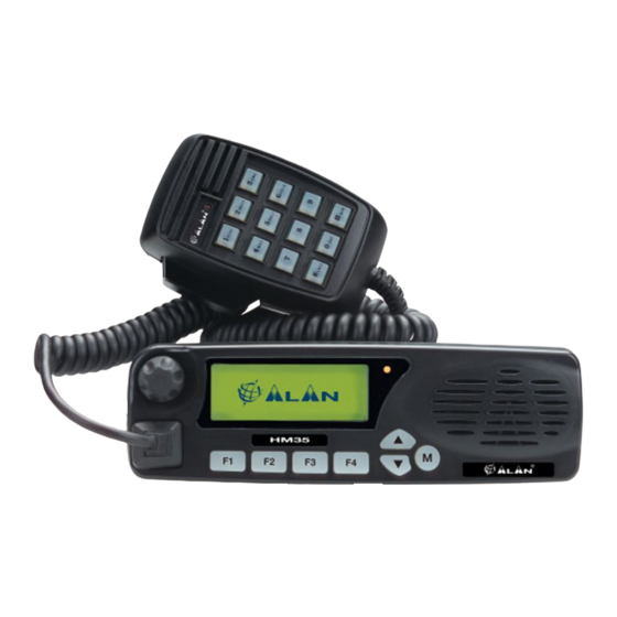
3 PARTI DELLA RADIO E FUNZIONI 3.1 Frontale Display - indica costantemente lo stato operativo dell’apparec- funzione di uscita dal menu (ESC). chio e vi guida nell’utilizzo delle funzioni tramite una serie di icone Tasti - tasti selezione canale/navigazione nel menu co- e messaggi. mandi Manopola Acceso/Spento-Volume - Usata per accendere/spe- Tasto – consente di entrare nel menu dei comandi e di confer- gnere la radio e per regolare il livello del volume di ascolto. -
Page 10: Lato Posteriore
3.2 Lato posteriore [9] Cavo di alimentazione - questo cavo rosso/nero va collegato consultate il Cap. 13. ad un’opportuna sorgente di alimentazione a 12,6 Vcc ± 10% (il [11] Presa antenna - questa presa di tipo SO 239 (UHF) serve per il rosso al positivo ed il nero al negativo), ad esempio alla batteria collegamento ad un’antenna adatta. E’ disponibile come opzio- di un veicolo. ne il connettore tipo BNC. Per ulteriori dettagli vi preghiamo di [10] Connettore Ingresso/Uscita – consente di collegare l’altopar- contattare il rivenditore di zona. lante esterno e di attivare dispositivi esterni. Per le connessioni Parti della radio e funzioni... -
Page 11: Verifica Delle Parti
4 VERIFICA DELLE PARTI 4.2 Microfono da palmo IMPORTANTE! Il microfono va ordinato a parte e può essere di due tipi: 4.1 Contenuto della confezione (a) Ricetrasmettitore (b) Cavo di alimentazione (c) Staffa da auto con viti e pomelli di fissaggio (d) Supporto per microfono con viti (e) Manuale d’uso (questo manuale!) A seconda della versione, alcune parti possono essere già fissate/collegate all’apparecchio. -
Page 12: Consigli Per L'installazione
5 CONSIGLI PER L’INSTALLAZIONE parazione ed il fissaggio del frontalino fate riferimento alle istruzioni fornite con il kit. ATTENZIONE! L’installazione dell’apparecchio va effettuata esclusivamente da personale specializzato e dotato di oppor- tuna strumentazione. Quanto sotto riportato costituisce un semplice complemento all’esperienza dell’installatore che si assume ogni responsabilità in merito. Un’errata installazione potrebbe danneggiare seriamente il ricetrasmettitore o creare danni a cose e persone. -
Page 13: Installazione Dell'antenna Veicolare
Il microfono da palmo non viene fornito con la radio, in quanto può 5.3.a Antenna essere di tipo standard (MK06/35) o con tastiera (MK06/35-K). Dopo aver verificato l’efficienza dell’antenna esterna, collegatela alla pre- Tuttavia l’installazione del supporto è la stessa. sa Antenna della radio (rif. par. 5.2) tramite un connettore adatto. 5.2 Installazione dell’antenna veicolare 5.3.b Alimentazione Collegate il cavo rosso/nero ad una sorgente di alimentazione a 12,6 Vcc... -
Page 14: Altoparlante Esterno (Opzionale)
procedura. In caso negativo, il comando sotto descritto non sarà acces- veicolo. sibile. Il ricetrasmettitore può essere programmato in modo che 1) Premete il pulsante per entrare nel menu comandi, quindi pre- l’altoparlante esterno sia escluso in modo da utilizzare solo quello mete ripetutamente il tasto fino ad evidenziare il menu interno. Per maggiori dettagli consultate il par 8.4. Lcd&Keypad (display e tastiera) 2) Premete ancora per accedere ai sottomenu disponibili 3) Premete ripetutamente il tasto... -
Page 15: Funzioni Di Base
6 FUNZIONI DI BASE 6.2 Regolazione del volume Per aumentare il volume, ruotate la manopola Acceso/Spento-Vo- IMPORTANTE! Una o più funzioni di quelle descritte da questo lume in senso orario. punto in poi possono essere state rese non disponibili dal ge- Per ridurre il volume, ruotatela in senso antiorario. -
Page 16: Regolazione Dello Squelch (Silenziamento Del Rumore Di Fondo)
6.5 Regolazione dello squelch (silenziamento del rumore 6.6 Monitor La funzione monitor serve principalmente a due scopi: di fondo) • Consente la ricezione di segnali estremamente deboli L’apparato dispone di un dispositivo per attenuare il fruscio di fondo • Disabilita temporaneamente il CTCSS/DCS e/o la chiamata selet- in assenza di segnali. Potete regolare la soglia di attivazione del di- tiva per consentirvi di ascoltare tutte le comunicazioni sul canale spositivo. -
Page 17: Timer Del Tempo Massimo Di Trasmissione (Tot)
renza), verificando che il LED di stato sia spento o lampeggiante se parlate per troppo tempo (tempo predeterminato in fase di pro- di arancione grammazione). In questo caso rilasciate il pulsante di trasmissione ed 3) Tenete premuto il tasto di trasmissione (PTT) del microfono da pal- aspettate alcuni secondi: le funzioni di trasmissione della radio saran- mo. Il LED di stato [8] a destra del display s’illumina di rosso per no ripristinate automaticamente. Per ulteriori informazioni rivolgetevi confermare che state trasmettendo al responsabile della rete o al vostro rivenditore. - Page 18 4) Premete per selezionare la potenza desiderata. 5) Uscite dal sottomenu premendo il tasto F4/ESC, quindi preme- telo nuovamente per uscire dal menu e tornare alla schermata di stand-by Funzioni di base...
-
Page 19: Utilizzo Dei Comandi/Opzioni
7 UTILIZZO DEI COMANDI/OPZIONI mostra il segno di spunta quando l’opzione è attiva. Inseri- te/togliete il simbolo premendo il tasto 7.1 Come navigare nel menu comandi • Se avete selezionato una chiamata selettiva, avviatene la tra- Fate riferimento al seguente diagramma. smissione premendo il tasto 1) Premendo una volta il tasto potete entrare nel menu comandi 5) Se necessario, confermate ulteriormente l’operazione con il tasto ed accedere ai cinque menu principali: (es. -
Page 20: Tabella Riassuntiva Del Menu Comandi
7.2 Tabella riassuntiva del menu comandi La seguente tabella riassume la funzionalità di ciascun sottomenu/impostazione disponibile nella radio. Più avanti ciascun sottomenu/impostazione viene spiegato in dettaglio nel paragrafo pertinente riportato nell’ultima colonna. TABELLA FUNZIONI DEL MENU COMANDI Menu principale Sottomenu Breve descrizione Tipo di comando o Valore disponibile Par. Radio Param Monitor Esclusione temporanea Squelch/CTCSS/ se monitor attivo (parametri radio) chiamata selettiva Squelch Regolazione del livello di squelch (dispositi- Indicatore a barra vo riduzione rumore di fondo) Power... - Page 21 Scan Scanning Avvio scansione (ricerca segnali sui canali 10.1.a Invio immediato premendo (funzioni programmati) scansione) Scan Esc Arresto temporaneo della scansione Arresto immediato 10.1.c Chan Del Esclusione temporanea di uno o più canali 10.1.b – Chan Del Esclusione immediata con dalla scansione Edit List Modifica della lista di scansione e del canale...
-
Page 22: Diagramma Del Menu
7.3 Diagramma del menu Radio Param Calls Scan Home chan Lcd&Keypad Switches Monitor Call 1 Scanning Contrast Squelch Call 2 Scan esc Light Aux. Out power User Call Chan Del Keypad Micr. Alarm Loc/Dist Emergency Edit List Pad Lock TlkAround Mic.Sens. -
Page 23: Significato Delle Icone Del Display
7.4 Significato delle icone del display Icona Significato Par. Icona Significato Par. Monitor attivo Scrambler attivato 10.6 Il segnale ricevuto contiene il corretto CTCSS/ PA attivato 10.7 Il segnale ricevuto contiene una chiamata Uscita ausiliaria attiva 10.8 selettiva valida Allarme esterno attivo 10.9 Scansione dei canali attiva 10.1.a La scansione è stata arrestata Alta potenza di trasmissione 10.1.c temporaneamente... -
Page 24: Tasti Funzione: Riepilogo Delle Abbreviazioni Visualizzate Sul Display
7.5 Tasti funzione riepilogo delle abbreviazioni visualizza- attiva la regolazione del livello di squelch te sul display regolazione contrasto regolazione luminosità Icona Significato attivazione/disattivazione uscita ausiliaria Invia chiamata pre impostata 1 chiama il canale principale Invia chiamata pre impostata 2 attiva/disattiva la modalità local/distance (vedi par. 10.4) Invia chiamata impostabile da microfono con tastiera regolazione sensibilità microfono attiva la funzione monitor selezione potenza alta/bassa attiva la funzione allarme tasto non programmato avvia la scansione elimina un canale dalla lista scansione arresta temporaneamente la scansione inserisce un canale nella lista scansione visualizza la lista dei canali in scansione... -
Page 25: Regolazione Sensibilità Microfono
8 PERSONALIZZAZIONE 8.2 Regolazione contrasto display A seconda del tipo di illuminazione e della temperatura ambientale potrebbe essere necessario variare il contrasto del display in modo da In questa sezione sono descritte le impostazioni che servono a rego- renderne la lettura più chiara. Per variare il contrasto: lare alcuni parametri dipendenti dall’ambiente o dall’utilizzo specifico 1) Premete il pulsante per entrare nel menu comandi, quindi usate della radio, ad esempio il contrasto del display, la retroilluminazione per evidenziare la voce di menu Lcd&Keypad (di- i tasti ecc. splay e tastiera) 2) Premete per entrare visualizzare i sottomenu disponibili 8.1 Regolazione sensibilità... -
Page 26: Esclusione Altoparlante Interno
(retroilluminazione). Il display visualizza: Per riattivare l’altoparlante interno eseguite nuovamente la • On - retroilluminazione sempre attiva procedura. Al punto 3 farete sparire il simbolo • Auto - retroilluminazione automatica. Si attiva non appena uti- Non scollegate l’altoparlante esterno quando quello interno è lizzate un comando qualsiasi e si disattiva dopo circa 20 se- disabilitato. -
Page 27: Uso Con Ctcss/Dcs E/O Chiamata Selettiva
9 USO CON CTCSS/DCS E/O CHIAMATA SELETTIVA 9.2.b Invio di una chiamata selettiva A seconda della programmazione, il vostro ricetrasmettitore può es- sere in grado di inviare fino a quattro chiamate selettive: 9.1 Ricezione • Call 1 (chiamata 1) – prima chiamata selettiva fissa In questa modalità operativa, la vostra radio è impostata in modo che, • Call 2 (chiamata 2) – seconda chiamata selettiva fissa l’audio venga abilitato solo quando ricevete la segnalazione CTCSS/ • User (utente) – chiamata selettiva variabile. Le cifre variabili si digi- DCS e/o la Chiamata selettiva appropriata. tano tramite il microfono con tastiera MK06/35-K (rif. par. 4.1.b) L’audio rimane perciò silenziato fino a quando vengono ricevuti il cor- • Emergency (emergenza) – è la chiamata selettiva di emergenza retto tono CTCSS, il corretto codice DCS e/o la chiamata selettiva (chiamata speciale inviata più volte con una procedura definita in... -
Page 28: Invio Di Una Chiamata Selettiva Variabile
Invio di una chiamata fissa selettiva da menu da menu”. fino ad evidenziare User Call, quindi 1) Assicuratevi che il canale sia libero, verificando che il LED di stato 3) Premete i tasti sia spento o lampeggiante di arancione. premete per effettuare la chiamata. 2) Premete il pulsante per entrare nel menu comandi, quindi usate per evidenziare la voce di menu Calls (chiamate). i tasti 9.2.d Invio di una chiamata selettiva di emergenza 3) Premete... -
Page 29: Funzioni Avanzate
10 FUNZIONI AVANZATE viene effettuata. Ovviamente, la lista dei canali in scansione deve comprendere almeno due canali. 10.1 Scansione dei canali Se premete il pulsante di trasmissione PTT durante la scansione dei canali, la radio si arresta su un canale predeterminato in fase Questa funzione è... -
Page 30: Variazione Della Lista Dei Canali
5) A seconda della operazione desiderata, premete il tasto funzione se, premete il pulsante per entrare nel menu comandi, quindi corrispondente come sotto riportato premete i tasti fino ad evidenziare sul display il menu F2 Aggiunta di nuovi canali alla lista Scan 1) Premete il tasto funzione F2 (chadd). Vedrete il primo dei canali 2) Premete ancora per accedere ai sottomenu disponibili non ancora inseriti nella lista di scansione. -
Page 31: Richiamo Rapido Del Canale Principale
rate definire come prioritario sabilitata. 5) Uscite dal sottomenu premendo il tasto F4/ESC, quindi preme- 5) Premete due volte il pulsante per memorizzare il nuovo ca- telo nuovamente per uscire dal menu e tornare alla schermata di nale prioritario ed uscire dalla lista di scansione stand-by. Il display visualizza l’icona 6) Se necessario, inserite nuovamente il precedente canale priori- Per riattivare la tastiera ripetete la procedura sopra descritta (al punto tario nella lista di scansione come sopra descritto 4 viene rimosso... -
Page 32: Talk Around
attenuatore inserito) non potete utilizzare il ripetitore quando ritorna in esercizio. Non appena le condizioni di ricezione ritornano alla normalità (es. vi siete spostati in una località priva di segnali troppo for- 10.6 Trasmissioni confidenziali ti), non dimenticate di disinserire l’attenuatore, diversamente (scheda scrambler opzionale) non sarete più... -
Page 33: Funzione Pa
10.7 Funzione PA 10.8 Uscita ausiliaria La presa posteriore Ingresso/Uscita della radio può comandare E’ possibile usare l’amplificatore audio dell’apparecchio per pilotare dispositivi esterni che si attivano/disattivano ogni volta che accendete/ un altoparlante esterno e amplificare la vostra voce. In questo spegnete l’apparecchio. Per abilitare questa funzione: modo disporrete di una sorta di “megafono mobile” da utilizzare per 1) Premete il pulsante per entrare nel menu comandi, quindi usate operazioni speciali. Per abilitare questa funzione: per evidenziare la voce di menu Switches (com- i tasti 1) Premete il pulsante per entrare nel menu comandi, quindi usate... - Page 34 per evidenziare la voce di menu Switches (com- i tasti mutazioni) 2) Premete per accedere ai sottomenu disponibili 3) Premete ripetutamente il tasto fino ad evidenziare il sotto- menu Alarm (uscita ausiliaria) 4) Premete per inserire il simbolo . Viene abilitata l’uscita ausi- liaria ed il display mostra in stand-by l’icona 5) Uscite dal sottomenu premendo il tasto F4/ESC, quindi preme- telo nuovamente per uscire dal menu e tornare alla schermata di stand-by...
-
Page 35: Pulizia E Manutenzione
11 PULIZIA E MANUTENZIONE 12 ACCESSORI OPZIONALI 11.1 Manutenzione della radio Gli accessori opzionali possono essere utilizzati per espandere le funzionalità del ricetrasmettitore e sono in continuo sviluppo. A prescindere dalle normali operazioni di pulizia e di controllo dell’efficienza delle connessioni, la radio non necessita di particolari Attualmente sono contemplati: • Microfono standard MK06/35 – microfono per uso generale con operazioni di manutenzione. -
Page 36: Connessioni
13 CONNESSIONI 17 Spare 2 Contatto supplementare per usi speciali 13.1 Connettore posteriore Ingresso/Uscita 18 Spare 1 Contatto supplementare per usi La seguente tabella riporta i collegamenti del connettore Ingresso/ speciali Uscita (DB25) posteriore: 19 Output 12V 100 mA max. 20 Backlight control input Nr. Nome segnale Note 21 INPUT/OUTPUT 2 AUX OUT... -
Page 37: Caratteristiche Tecniche
14 CARATTERISTICHE TECNICHE 14.1 Metodi di test • ETS 300-086 / ETS 300-113 (scheda “modem board” opzionale) • IEC 529 IP54 and MIL STD 810 C/D/E 14.2 Tabella caratteristiche Generali Caratteristica Unità Valore/Condizioni di misura Frequenza da 136 a 174 Banda operativa Numero canali programmabili Fino a 255 Spaziatura canali 12,5 / 20 / 25 Incrementi di frequenza 5 / 6,25 Alimentazione nominale 12,6 ± 10% Consumo... - Page 38 Trasmettitore Potenza di uscita (±1 dB) 4 / 25 Emissioni spurie µW da 9 KHz a 1 GHz < -36 dBm da 1 a 4 GHz < -30 dBm Sistema di modulazione FM (F3E) / PM (G3E) Deviazione massima ± 2,5 (a 12,5 KHz) / ±5 (a 25 KHz) Attenuazione potenza sul canale adiacente < -60 (a 12,5 KHz) / -70 (a 20-25 KHz) Ricevitore Configurazione Doppia conversione...
- Page 39 Un dispositivo di sezionamento adatto deve essere previsto nell’impianto elettrico. Tale dispositivo deve disconnettere entrambi i poli simultaneamente.
- Page 40 English...
- Page 42 IN THIS MANUAL… 5.3.a Antenna 5.3.b Power supply 5.3.c Connection/Disconnection of the microphone 10 GENERAL INFORMATION FOR THE HM35 SERIES 5.3.d External speaker (optional) ABOVE ALL… SAFETY! BASIC OPERATIONS 2.1 Conventions and Symbols Used in This Manual 6.1 Turning HM35 on/off 2.2 Warnings Volume adjustment 2.3 Security 6.3 Channel selection 2.3.a General precautions...
-
Page 43: In This Manual
CUSTOMIZATION 11 CLEANING AND MAINTENANCE 8.1 Adjustment of microphone sensitivity 11.1 Maintenance of the radio 8.2 Adjustment of display contrast 11.1.a Cleaning the radio 8.3 Backlight adjustment 11.1.b Connectors Exclusion of internal speaker USE WITH CTCSS/DCS AND/OR SELECTIVE CALLS 12 OPTIONAL ACCESSORIES 9.1 Reception 13 CONNECTIONS 9.2 Transmission 9.2.a CTCSS/DCS Transmission 13.1 Input/Output rear connector 9.2.b Sending a selective call 14 TECHNICAL SPECIFICATIONS... -
Page 44: General Information For The Hm35 Series
Notes such as this one indicate practical advice that we according to frequency band. recommend following for simplified use of the device, and for HM35 is a robust vehicular radio “SYSTEM” equipped with highly optimal performance. advanced functions that have been designed for ease of use and Warning symbols such as this one indicate a crucial descrip- flexibility for various needs, thanks to “Flash EEProm” technology. -
Page 45: Security
• Pay attention to environmental conditions. Your radio was de- 2.3 Security signed to be used in extreme environmental conditions, though Your portable ALAN HM35 transceiver is designed to give you excessive heat or cold should be avoided (outside the values of maximum security and reliability. As with all electrical devi- the specifications outlined in Chapt. 14). -
Page 46: Assistance
(EME) at radio frequency (RF), and as such must be installed and placed in operating conditions that are in conformity with the in- structions contained in this manual and with current regulations. Failure to follow these instructions can cause personal injury and/ or serious malfunction of the device. • It is very important to follow the requirements relative to the pre- vention of radio frequency exposure. Unauthorized changes or modifications to this device may invalidate conformity to regula- tions. All changes or modifications to the radio must be approved in writing by the manufacturer. • Ensure that your power supply corresponds to the values cited in this manual. In case of doubt, contact your local vendor. This product conforms to requirements of the Council Directives 2004/108/CE and 2006/95/CE regarding the acknowledgement of the laws of the Member States, and relating to electromagnetic compatibility. 2.4 Assistance We urge you to write the serial number of your transceiver in the space provided below. This number is found on the transceiver’s identifying label. This number will be useful in the event of repair/assistance and/ or loss and/or theft of the device. -
Page 47: Parts Of The Radio And Their Use
3 PARTS OF THE RADIO AND THEIR USE 3.1 Front panel Display - constantly displays the operating status of the device with fixed selective calls. and guides the use of various functions through a series of icons The F4/ESC button is also used for exiting a menu (ESC). and messages. (up)/ (down) buttons – for channel selection and naviga- On/Off-Volume knob – used for turning the radio on/off and for tion of the command menu. adjustment of reception volume. button – for accessing the command menu and confirming Microphone socket – this RJ type socket connects the standard the option shown on the display. hand-held (MK06/35) or keypad microphone (MK06/35-K) to the Internal speaker. radio. Status LED – is lit with different colours to indicate the radio’s [4] Programmable function keys F1, F2, F3 and F4/ESC enable the status (transmission, busy channel, etc.) user to recall commonly used functions or can be programmed Parts of the radio and their use... -
Page 48: Rear Panel
3.2 Rear panel [9] Power cable – this red/black cable connects to a 12,6 Vdc ± [11] Antenna socket - this SO 239 (UHF) socket is for connecting a 10% power source (red is positive and black is negative), for suitable antenna. Another option is to use a BNC-type connec- example to the vehicle battery. tor. For further details, please contact your local vendor. [10] Input/output connector – for connection to the external speaker and for activation of external devices. For connections, refer to Par. -
Page 49: Checking The Parts
4 CHECKING THE PARTS 4.2. Hand-held microphone IMPORTANT! The microphone is ordered separately, and can be one of the following two types: 4.1. Package contents (a) Transceiver (b) P ower cable (c) Vehicle bracket with screws and knobs for mounting (d) M ounting piece for microphone, with screws (e) User’s manual (this manual!) Depending on the model, some parts may already be attached/ connected to the device. If any parts are missing or damaged, contact your vendor as soon as possible. -
Page 50: Advice For Installation
5 ADVICE FOR INSTALLATION For separation and mounting of the front panel, refer to the instruc- tions found in the kit. WARNING! Installation of this device must be performed by qualified persons who are equipped with the proper tools. The information provided below are designed solely as a comple- ment to the experience held by the technician, who should as- sume full responsibility for the installation. -
Page 51: Installation Of The Vehicular Antenna
cause accidental activation of the push to talk (PTT) button to the CTE International technical office. and therefore transmission. 5.3.a Antenna After verifying the efficiency of the external antenna, connect it to the Neither the standard (MK06/35) nor the keyboard (MK06/35-K) radio’s Antenna socket (refer to par. 5.2) using a suitable connector. microphones are supplied with the radio; however, installation of the mount is the same for both. -
Page 52: External Speaker (Optional)
not be accessible. is excluded and only the internal one is used. For further de- 1) Press the button to access the command menu, then press tails, refer to par. 8.4. buttons repeatedly until the Lcd&Keypad menu is the highlighted. 2) Press the again to view the available sub-menus. -
Page 53: Basic Operations
CTCSS/DCS tone/code. For further details, refer to dio network administrator. For information regarding the use of Chapt. 9. menu commands and function keys, refer to Chapt. 7. • Selective call - allows the user to send and receive calls from a user or group. 6.1 Turning HM35 on/off When you receive a valid selective call, the status LED will flash oran- ge and an audio signal will alert you to the incoming call. For further To turn on the radio, turn the On/Off-Volume knob clockwise until details, refer to Chapt. 9. you hear a click. -
Page 54: Monitor
ground noise when no signal is being picked up. You can regulate the 6.6.a Monitor from the menu threshold of device activation. 1) Press the button to access the command menu, then use the buttons to highlight Radio Param (radio parameters) from 1) Press the button to access the command menu, then use the buttons to highlight the Radio Param option. the menu. 2) Press the button once more to view the available sub-menus, 2) Press to view the sub-menus available and until the Monitor sub-menu is high lighted. then until the sub-menu Squelch (adjustment of squelch to insert beside Monitor. This indicates that the monitor levels) is highlighted. -
Page 55: Time Out Timer (Tot)
Begin speaking only after having pressed the PTT button and do This setting is not available by the end user. For further details, not release it until you have finished speaking, otherwise all or please contact your radio network administrator. part of your message will not be transmitted. -
Page 56: Use Of Commands/Options
7 USE OF COMMANDS/OPTIONS will appear on the display when the option is activated. Insert/ remove the symbol by pressing the button. • If you have selected a selective call, begin transmission by 7.1 How to navigate the command menu pressing the button. Refer to the following diagram. 5) If necessary, confirm the change once more with the button 1) Pressing the button once opens the command menu and di- (e.g. in the case of variable selective calls) splays the five main menus:... -
Page 57: Summary Table For The Command Menu
7.2 Summary table for the command menu The following table summarizes the functions of each sub-menu/setting available on your radio. Each sub-menu/setting will be explained in detail, and its location can be found by referring to the last column of this table. SUMMARY TABLE FOR COMMAND MENU Main Menu Sub-menu Brief Description Type of command or Value available Par. Radio Param Monitor Temporary exclusion Squelch/CTCSS/selec- if monitor is activated tive calling Squelch Squelch regulation (suppression of back- Bar indicator ground noise in standby) Power... - Page 58 Scan Scanning 10.1.a Start scanning (searches for signals on pro- Press to start immediately grammed channels) Scan Esc 10.1.c Temporary pause in scanning Immediate pause Chan Del 10.1.b Temporary exclusion of one or more channels – Chan Del Immediate exclusion with from scanning Edit List 10.1.d Modification of scanning list and of priority Modified using the function keys channel Home Chan 10.2 Rapid recall of most commonly used channel...
-
Page 59: Menu Diagram
7.3 Menu diagram Radio Param Calls Scan Home chan Lcd&Keypad Switches Monitor Call 1 Scanning Contrast Squelch Call 2 Scan esc Light Aux. Out power User Call Chan Del Keypad Micr. Alarm Loc/Dist Emergency Edit List Pad Lock TlkAround Mic.Sens. Scrambler Int.Spkr Off Use of commands/options... -
Page 60: Meanings Of Display Icons
7.4 Meanings of display icons Icon Meaning Par. Icon Meaning Par. 10.6 Monitor is activated Scrambler activated 10.7 Signal received contains correct CTCSS/DSC PA activated 10.8 Signal received contains a valid selective call Auxiliary output is activated 10.1.a 10.9 Scanning of active channels External alarm is activated 10.1.c 6.7.c Scanning is temporarily paused High transmission power 10.2 6.7.c Home channel was called Low transmission power 10.3 10.4 Lock on keypad microphone MK06/35-K is ac- Receiver sensitivity attenuator deactivated (Di-... -
Page 61: Meaning Of Function Key Icons
7.5 Meaning of function key icons Activates the regulation of squelch level Adjusts contrast Icon Meaning Adjusts brightness Sends fixed selective call - Call 1 Activates auxiliary output Sends fixed selective call - Call 2 Sends a call to the priority channel Send variable user-defined selective call Activates/deactivates local/distance mode Monitor is activated Adjusts microphone sensitivity Selects Hi/Lo power Alarm is activated Starts scan Key not assigned Interrupts scan Deletes a channel from the scan list Shows the scan list Inserts a channel in the scan list Sends an emergency call Activates PA function (public address) Activates talk around function Activates the MK06/35-K mike... -
Page 62: Customization
8 CUSTOMIZATION 8.2 Adjustment of display contrast Depending on your ambiental light and temperature, you may wish to change the display contrast in order to better view the screen. To This section describes the settings that regulate various parameters, change the contrast: depending on environment and specific use of the radio; for example, 1) Press the button to access the command menu, then use the display contrast, backlighting, etc. buttons to highlight the Lcd&Keypad option. 2) Press to view the sub-menus available. 8.1 Adjustment of microphone sensitivity 3) Press the buttons until the Contrast (adjustment of di- Normally, the sensitivity of the microphone allows the user to speak at splay contrast) sub-menu is highlighted, then press to enter a distance of up to 10 centimetres from the microphone. However, if... -
Page 63: Exclusion Of Internal Speaker
• Auto – backlight is automatic - will activate as soon as you use any command, and will deactivate approximately 20 seconds after the last command is given. • Off – backlight deactivated 4) Press the button repeatedly until the desired setting is se- lected. 5) Exit the sub-menu by pressing the F4/ESC button, then press it a second time to exit the main menu and return to the standby screen. 8.4 Exclusion of internal speaker If your transceiver is connected to an (optional) external speaker, you may wish under some conditions to use only the external speaker, and exclude the internal one. To do this: 1) Press the button to access the command menu, then use the... -
Page 64: Use With Ctcss/Dcs And/Or Selective Calls
9 USE WITH CTCSS/DCS AND/OR SELECTIVE CALLS 9.2.b Sending a selective call Depending on the programming, your transceiver may be able to send 9.1 Reception up to four selective calls: In this operating mode, your radio is programmed so that the audio is • Call 1 – first selective call (fixed) activated only when receiving a correct CTCSS/DCS and/or selective • Call 2 – second selective call (fixed) call signal. • User – variable selective call; the variable digits can be keyed into The audio will thus remain silent until you receive a correct CTCSS the MK06/35-K keypad microphone (refer to. par. 4.1.b). tone, a correct DCS code, and/or a valid selective call. • Emergency – selective call for emergencies (special call sent re- • If a correct CTCSS/DCS signal is received, the status LED will peatedly, and defined during the programming phase). -
Page 65: Sending A Variable Selective Call
is off or flashing orange. 9.2.d Sending an emergency selective call 2) Press the button to access the command menu, then use the This is a special call that is sent repeatedly in cycles on a predefined buttons to highlight the Calls option. channel based on the radio’s programming. 3) Press to view the selective calls available: Use this emergency call only if you find yourself in a real con- • Call1 – fixed call 1 dition of necessity which requires assistance. Speak to your • Call2 – fixed call 2 radio network administrator about its use. -
Page 66: Advanced Functions
10 ADVANCED FUNCTIONS the list of scanning channels must include at least two channels. If you press the PTT transmission button during channel scanning, 10.1 Channel scanning the radio will pause on a predetermined channel, chosen during the programming phase (this will be the priority channel or another This function is particularly helpful when multiple channels have been predefined one), and will begin transmission. -
Page 67: Changing The Channel Scanning List
2) Press the buttons until the channel you desire appears on from scanning) sub-menu is highlighted and press . Scanning the screen. will stop on the channel currently selected, and the standby icon 3) Press the button to memorize the channel in the scanning list. will appear on the display. To restart scanning, repeat the procedure outlined above. 4) Exit the sub-menu by pressing the F4/ESC button, then press it a second time to exit the main menu and return to the standby screen. If this command is used frequently, we suggest you program F3 Deleting channels from the list it into one of the function keys. Contact your radio network 1) Press the buttons repeatedly until that channel you wish administrator for further details. -
Page 68: Rapid Recall Of Home Channel
a second time to exit the main menu and return to the standby microphone PTT, and some function keys will still remain active screen. (depending on the device’s programming). 10.2 Rapid recall of home channel 10.4 Signal reception attenuator If you are in an area where radio signals are too strong (e.g., near a This function allows you to quickly recall the channel most frequently used (home channel). -
Page 69: Talk Around
10.5 Talk Around To activate the scrambler: 1) Ensure your receiving party has activated their scrambler. If you are operating with a repeater and it breaks down, you can use 2) Press the button to access the commend menu, then use the the Talk Around function to communicate with nearby stations by buttons to highlight the Radio Param option. bypassing the repeater. To activate this function: 1) Select a semi-duplex channel (otherwise the Talk Around function 3) Press to view the available sub-menus. 4) Press the buttons repeatedly until the Scrambler sub- cannot be activated) menu is highlighted. 2) Press the button to access the command menu, then use the buttons to highlight the Radio Param option. 5) Press to insert the symbol. The scrambler function is acti-... -
Page 70: Auxiliary Output
5) Exit the sub-menu by pressing the F4/ESC button, then press it 4) Press to insert the symbol. The audio amplifier will be acti- a second time to exit the main menu and return to the standby vated, and the icon will appear on the display. screen. 5) Exit the sub-menu by pressing the F4/ESC button, then press it To reactivate normal radio functions, follow the procedure outlined a second time to exit the main menu and return to the standby above. -
Page 71: Cleaning And Maintenance
11 CLEANING AND MAINTENANCE Aside from the normal cleaning and connection efficiency check, your radio does not require any particular maintenance. As with all electrical devices, your radio requires periodic la- boratory testing, otherwise its performance cannot be gua- ranteed. For further details, contact your radio network admi- nistrator or CTE International technical office. 11.1.a Cleaning the radio Carefully polish the radio using a soft, clean cloth that does not have loose fibers. If the radio is very dirty, slightly dampen the cloth in a solution of 90% water and 10% neutral soap. -
Page 72: Optional Accessories
12 OPTIONAL ACCESSORIES Optional accessories can be used to expand the range of functions available with your radio. We are constantly developing new options for you, and are pleased to list below the accessories we currently offer: • MK06/35 standard microphone – microphone for general use, with PTT transmission button. • MK06/35-K keypad microphone – along with the standard mi- crophone functions, it allows the user to make variable selective calls (if activated during the programming phase). -
Page 73: Connections
13 CONNECTIONS EXT SPEAKER + Spare 2 Additional contact for special use 13.1 Input/Output rear connector Spare 1 Additional contact for special use The following table outlines the connections from the rear Input/Output (DB25) connector: Output 12V 100 mA max. Backlight control input INPUT/OUTPUT 2 Signal name Notes INPUT/OUTPUT 1 AUX OUT External alarm input Not connected Emergency switch - input EXT SPEAKER Ignition sense input... -
Page 74: Technical Specifications
14 TECHNICAL SPECIFICATIONS 14.1 Test methods • ETS 300-086 / ETS 300-113 (optional “modem board”) • IEC 529 IP54 and MIL STD 810 C/D/E 14.2 Specifications table General Characteristic Units Value/Measurements conditions Frequency from 136 to 174 Operating Band Number of Programmable Channels up to 255 Channel Spacing 12.5 / 20 / 25 Frequency Steps 5 / 6.25 Rated Power Supply 12,6 ± 10% Current drain Stand-by 0.4 (or less) 0.6 @ the maximum AF power... - Page 75 Transmitter Output Power (±1 dB) 4 / 25 Spurious Emissions µW from 9 KHz to 1 GHz < -36 dBm from 1 to 4 GHz < -30 dBm Modulation System FM (F3E) / PM (G3E) Maximum Deviation ± 2.5 (@ 12.5 KHz) / ±5 (@ 25 KHz) Adjacent Channel Power Attenuation < -60 (@ 12.5 KHz) / -70 (@ 20-25 KHz) Receiver Configuration Double Conversion Superetherodyne...
- Page 77 A readily accessible disconnect device shall be incorporated in the installation wiring. The disconnect device shall disconnect both poles simultaneously.
- Page 78 Deutsch...
- Page 80 In diesem Handbuch… 5.3.a Antenne 5.3.b Spannungsversorgung ALLGEMEINE INFORMATIONEN ZUR HM35 SERIE 5.3.c Anschluss/Trennung des Mikrofons 5.3.d Externer Lautsprecher (optional) ALLEM VORAN… SICHERHEIT! Bedeutungen und Symbole in diesem Handbuch GRUNDFUNKTIONEN Anmerkungen HM35 Ein-/ausschalten Sicherheit Lautstärkeeinstellung 2.3.a Allgemeine Sicherheitshinweise Kanalwahl 2.3.b Einsatzbedingungen/Gebrauch Empfang 2.3.c Installation...
- Page 81 10.8 Rückseitiger SUB-D-Anschluss ANPASSEN 10.9 Externer Alarm Einstellen der Mikrofonempfindlichkeit Displaykontrast einstellen 11 PFLEGE UND WARTUNG Hintergrundbeleuchtung einstellen 11.1 Wartung des Funkgerätes Abschalten des internen Lautsprechers 11.1.a Reinigung des Funkgerätes 11.1.b Anschlüsse CTCSS/DCS- UND/ODER SELEKTIVRUFVERFAHREN Empfang 12 OPTIONALES ZUBEHÖR Senden 9.2.a Senden mit CTCSS/DCS-Kennung 13 ANSCHLÜSSE 9.2.b Aussenden eines normalen Selektivrufs...
-
Page 82: In Diesem Handbuch
Ihrem Funkgerät zu vermeiden und um potentielle Gefahren werden können. für Sie oder andere auszuschließen. Die technischen Daten der HM35 Serie entsprechen den europäischen • Bezeichnungen von Tasten oder Schlüsselbegriffen sind fett Standards ETS 300-086 und ETS 300-113; darüber hinaus hervorgehoben. -
Page 83: Sicherheit
Tuch ab. 2.3 Sicherheit • Verwenden Sie ausschließlich Originalzubehör; anderes Zubehör Die ALAN HM 35 Serie wurde sorgfältig entwickelt, um Ihnen könnte Schäden an Ihrem Funkgerät hervorrufen. jahrelangen, sicheren und zuverlässigen Funkbetrieb zu • Schalten Sie das Funkgerät aus, bevor Sie es reinigen. Beachten ermöglichen. -
Page 84: Installation
explosionsgefährdeten Umgebung. elektromagnetischer Verträglichkeit und Niederspannung. • Halten Sie das Funkgerät mit seiner Antenne während des Sendens möglichst körperfern und berühren Sie die Antenne nicht. Das Funkgerät funktioniert am besten, wenn das Mikrofon ca. 5-10 cm vom Mund entfernt ist und senkrecht gehalten wird. 2.4 Seriennummer Notieren Sie die Seriennummer Ihres Funkgerätes auf dem unten dafür 2.3.c Installation... -
Page 85: Gehäuseteile Und Ihre Funktionen
3 GEHÄUSETEILE UND IHRE FUNKTIONEN 3.1 Frontseite Selektivrufen belegt werden. D F4/ESC Taste dient zum Verlassen des Menüs. Display – zeigt konstant den Betriebsstatus an und führt durch (aufwärts)/ (abwärts) Tasten – zur Kanalwahl und zum die verschieden Funktionen anhand einer Reihe von Symbolen Navigieren durch das Befehlsmenü. -
Page 86: Rückseite
3.2 Rückseite Spannungsversorgung – dieses rot/schwarze Kabel wird an eine [11] Antennen Anschlussbuchse – An diese SO 239 (UHF) wird eine 12,6 Vdc ± 10% VDC Spannungsquelle angeschlossen (rot ist passende Antenne angeschlossen. Optional kann auch ein BNC PLUS und Schwarz ist MINUS), wie z.B. an die Fahrzeugbatterie. Stecker über einen entsprechenden Adapter angeschlossen [10] Rückseitiger 25 pol Sub-D-Anschluss –... -
Page 87: Überprüfung Des Lieferumfangs
4 ÜBERPRÜFUNG DES LIEFERUMFANGS 4.2 Mikrofon Wichtig! Das Mikrofon wird separat bestellt, es stehen folgende zwei 4.1 Lieferumfang Versionen zur Auswahl: (a) Funkgerät (b) Anschlusskabel (c) Fahrzeughalterung mit Schrauben und Drehknöpfen für die Montage (d) Mikrofonhalterung mit Schrauben (e) Bedienungsanleitung (dieses Handbuch!) Je nach Modell können einige Zubehörteile bereits am Gerät montiert sein. -
Page 88: Hinweise Zur Montage
5 HINWEISE ZUR MONTAGE Lieferumfang befindlichen Schrauben. 5.1.b Abnehmbares Frontelement ACHTUNG! Die Installation dieser Vorrichtung muss von Um Behinderungen des Fahrers/Beifahrers zu vermeiden, kann die qualifiziertem Fachpersonal korrektem Werkzeug abnehmbare Frontblende mit dem optional erhältlichen Installationssatz durchgeführt werden. Die nachfolgenden Informationen dienen auf dem Armaturenbrett angebracht werden. -
Page 89: Anbringung Der Mobilantenne
Abstimmung des SWR sollte durch den Einrichter Ihrer Funkanlage Positionieren Sie die Mikrofonhalterung so, dass das mit einem passenden Instrument erfolgen, sobald die Antenne in Mikrofonkabel nicht gestrafft wird und das Mikrofon offenem Gelände angebracht wurde. fest in der Halterung aufliegt und das Kabel auch bei herausgenommenem Mikrofon nicht unter Zug steht. -
Page 90: Anschluss/Trennung Des Mikrofons
Drücken Sie die Taste ein zweites Mal um das Hauptmenü zu 5.3.c Anschluss/Trennung des Mikrofons verlassen und zur Standby-Ansicht zu gelangen. Wie bereits zuvor erwähnt, stehen zwei verschieden Mikrofontypen zur Auswahl (nicht im Lieferumfang): Diese Prozedur sollte vorgenommen werden, bevor Sie •... -
Page 91: Grundfunktionen
Funkgespräch, das auf dem gewählten Funkkanal ausgesendet Kapitel 7. wird, mit. • CTCSS/DCS - soweit programmiert, erlaubt diese Betriebsart, 6.1 HM35 Ein-/ausschalten dass nur Teilnehmer eines Funknetzes mit der gleichen CTCSS/ Um das Gerät einzuschalten, drehen Sie den OFF/VOLUME-Regler über DCS Toncodierung auf einen Kanal zu hören sind. -
Page 92: Squelcheinstellung (Rauschunterdrückung)
LED orange und es ertönt ein Audiosignal, das den eingehenden Ruf 4) Halten Sie die Taste gedrückt, bis ein kontinuierliches ankündigt. Weitere Informationen entnehmen Sie bitte Kapitel 9. Rauschen zu hören ist. Die Betriebsarten CTCSS/DCS und Selektivruf können 5) Wenn Sie kein Signal empfangen (nur Rauschen), drücken Sie miteinander kombiniert werden. -
Page 93: Monitorfunktion Über Menü Einstellen
den Sendebetrieb. 6.6.a Monitorfunktion über Menü einstellen 4) Sprechen Sie in normaler Lautstärke mit einem Abstand von 5 – 10 1) Rufen Sie durch Drücken der Taste das Hauptmenü auf. cm in das Mikrofon. Tasten, bis das Menü Radio Drücken Sie dann die 5) Wenn Sie die Übertragung beenden wollen, lassen sie die PTT-Taste Param (Funkgeräte Parameter) erscheint. -
Page 94: Sendesperre Auf Belegten Kanälen (Bclo - Busy Channel Lock Out)
4) Drücken Sie um die gewünschte Sendeleistung einzustellen. 6.7.b Sendesperre auf belegten Kanälen (BCLO - Busy Channel 5) Verlassen Sie das Untermenü, indem Sie die F4/ESC Taste Lock Out) drücken. Durch nochmaliges Drücken der Taste verlassen Sie das Das Funkgerät könnte mit einer PTT-Sperre programmiert sein, die Hauptmenü... -
Page 95: Gebrauch Von Befehlen/Optionen
7 GEBRAUCH VON BEFEHLEN/OPTIONEN eingefügt bzw. entfernt werden. • Wenn Sie einen Selektivrufton gewählt haben, können Sie die Übertragung durch Drücken der Taste aktivieren. 7.1 Wie man das Befehlsmenü steuert 5) Soweit notwendig, bestätigen Sie die Änderungen durch Drücken Beachten Sie das nachfolgende Diagramm. Taste (z.B. -
Page 96: Tabellarische Zusammenfassung Des Befehlsmenüs
7.2 Tabellarische Zusammenfassung des Befehlsmenüs Die nachfolgende Tabelle gibt eine Zusammenfassung aller in den Untermenüs zur Verfügung stehenden Funktionen/Einstellungen. Jedes Untermenü und jede Einstellung wird im Detail erklärt und in der letzten Spalte wird noch einmal der entsprechende Abschnitt mit angegeben. ZUSAMMENFASSUNG DES BEFEHLSMENÜS Hauptmenü... - Page 97 Startet den Kanalsuchlauf (Suche nach Signalen Scanning 10.1.a Drücken Sie zum sofortigen Starten auf den programmierten Kanälen) Scan Esc Kurzzeitige Unterbrechung des Kanalsuchlaufs Sofortige Pause 10.1.c Scan Kurzzeitiges Überspringen/Löschen eines oder Kurzzeitiges Überspringen/Löschen mit – Chan Del 10.1.b mehrerer Kanäle im Kanalsuchlauf Chan Del Modifizieren der Suchlaufliste und des Prioritäts- Edit List...
-
Page 98: Menü Diagramm
7.3 Menü Diagramm Radio Param Calls Scan Home chan Lcd&Keypad Switches Monitor Call 1 Scanning Contrast Squelch Call 2 Scan esc Light Aux. Out power User Call Chan Del Keypad Micr. Alarm Loc/Dist Emergency Edit List Pad Lock TlkAround Mic.Sens. Scrambler Int.Spkr Off Gebrauch von befehlen/optionen... -
Page 99: Symbolerklärungen
7.4 Symbolerklärungen Symbol Beschreibung Bezug Symbol Beschreibung Bezug Scrambler ist aktiviert 10.6 Monitor ist aktiviert PA (Durchsageverstärker) ist aktiviert 10.7 Das empfangene Signal enthält die korrekte 9.1. CTCSS/DSC-Kennung Zusätzlicher Ausgang wird aktiviert 10.8 Das empfangene Signal enthält eine gültige Se- lektivruftonfolge Externer Alarm ist aktiviert 10.9... -
Page 100: Symbole Bei Betätigen Einer Funktionstaste
7.5 Symbole bei Betätigen einer Funktionstaste Aktiviert den Squelchregler Jeder Funktionstaste können Befehle/Funktionen zugewiesen werden. In der nachfolgenden Tabelle erhalten Sie eine Beschreibung der Stellt den Kontrast ein Symbole, die erscheinen, sobald eine Funktionstaste betätigt wird. Stellt die Hintergrundbeleuchtung ein Symbol Beschreibung Aktiviert den zusätzlichen Ausgang... -
Page 101: Anpassen
8 ANPASSEN drücken. Durch nochmaliges Drücken der Taste verlassen Sie das Hauptmenü und das Display schaltet in den Standby-Modus. Dieser Abschnitt beschreibt die Einstellung verschiedener 8.2 Displaykontrast einstellen Parameter, die das Funkgerät an Ihre Bedürfnisse anpasst und Sie können den Displaykontrast einstellen und somit das Display den alle grundlegenden Daten für den Betrieb beinhalten (z.B. -
Page 102: Abschalten Des Internen Lautsprechers
Int.Spkr Off (internen Lautsprecher abschalten) erscheint. 1) Rufen Sie durch Drücken der Taste das Befehlsmenü auf. 4) Drücken Sie die Taste um das Symbol neben der die Option Lcd&Keypad aus. Wählen Sie über die Tasten entsprechenden Option einzufügen. (Mit anderen Worten, der 2) Drücken Sie um das Untermenü... -
Page 103: Ctcss/Dcs- Und/Oder Selektivrufverfahren
9 CTCSS/DCS- UND/ODER 9.2 Senden SELEKTIVRUFVERFAHREN 9.2.a Senden mit CTCSS/DCS-Kennung Wurde Ihr Funkgerät bereits mit einer CTCSS- oder DCS-Kennung 9.1 Empfang programmiert, müssen Sie keine weiteren Einstellungen mehr Es könnte sein, dass Ihr Funkgerät so eingestellt ist, dass während vornehmen. Der CTCSS- oder DCS-Kennungston wird automatisch im des CTCSS/DCS- und/oder des Selektivruf- Verfahrens, der Sendemodus mit ausgestrahlt (Funkgerät zeigt diese Betriebsart nicht Lautsprecher Ihres Gerätes sich nur dann einschaltet, wenn der... -
Page 104: Einen Variablen Selektivruf Absetzen
Sie in Kapitel 13. 9.2.c Einen variablen Selektivruf absetzen Einen festgelegten Selektivruf über die Funktionstasten absetzen: Diese Funktion steht nur unter Verwendung des Tastaturmikrofons 1) Stellen Sie sicher, dass der Kanal nicht belegt ist (ansonsten (Modell MK06/35-K) zur Verfügung. verursachen Sie Störungen), d.h. die Status LED ist abgeschaltet Soweit auf einem Kanal ein variabler Selektivruf programmiert oder blinkt orange. -
Page 105: Weitere Funktionen
10 WEITERE FUNKTIONEN Die Aussendung des Notfall Selektivrufs kann auch über den rückseitigen Sub-D-Anschluss erfolgen. Absetzen über Mikrofon 10.1 Kanalsuchlauf Halten Sie die 3EMG Taste am Tastaturmikrofon gedrückt bis der Diese Funktion ist besonders nützlich, wenn mehrere Kanäle Notfall Selektivruf abgesetzt wurde und lassen Sie dann erst die Taste programmiert wurden. -
Page 106: Kurzzeitiges Überspringen Von Kanälen Im Kanalsuchlauf
außer Funktion. 10.1.c Kurzzeitige Stoppen des Kanalsuchlaufs 1) Sobald der Kanalsuchlauf kurzzeitig auf einem Kanal ihres Wenn die Kanalsuchliste leer ist, ertönt ein Fehlerquittungston, Interesses stoppt, drücken Sie die Taste um das Befehlsmenü der signalisiert, dass der Kanalsuchlauf nicht gestartet werden Tasten bis das Scan Menü... -
Page 107: Direktzugriff Auf Den Hauskanal
Kanalsuchlaufliste eingefügt werden kann erscheint im Display. F1 Prioritätskanal ändern Oberhalb der vier Funktionstasten kann auch folgendes im Display 1) Entfernen Sie zunächst den vordefinierten Prioritätskanal aus der erscheinen: Suchlaufliste, in dem Sie oben genannte Anweisungen befolgen. 2) Wählen Sie nun den Kanal an, den Sie als Prioritätskanal in der padd chadd chdel... -
Page 108: Eingangsabschwächer
Wenn Sie das Tastaturmikrofon MK06/35-K verwenden, kann einsetzen: die Tastaturverrieglung der Mikrofontastatur aktiviert werden um 1) Rufen Sie durch Drücken der Taste das Befehlsmenü auf. die Option Radio Param versehentliches Betätigen von Tasten zu vermeiden. Wählen Sie über die Tasten 1) Rufen Sie durch Drücken der Taste das Befehlsmenü... -
Page 109: Rundruf
10.5 Rundruf 10.6 Senden mit Sprachverschleierung (optionaler Scrambler) Möglicherweise benutzen Sie einen Repeater, mit dessen Hilfe Ihr Betriebsfunkgerät kann optional mit einem internen Scrambler ausgestattet werden. Es handelt sich hierbei um einen Abhörschutz die einzelnen Funkgeräte über größere Entfernungen hinweg Ihres Funkverkehrs. -
Page 110: Durchsageverstärker (Pa Funktion)
10.7 Durchsageverstärker (PA Funktion) 10.8 Rückseitiger SUB-D-Anschluss Mit Hilfe der PA-Funktion kann das Funkgerät als Lautsprechersystem Der SUB-D-Anschluss auf der Rückseite des Funkgerätes kann arbeiten. Der Ton wird durch das Funkgerät zu einem externen (angeschlossene) externe Geräte überwachen, die jedes Mal aktiviert/ Lautsprecher geleitet, der an Ihrem Fahrzeug montiert ist. -
Page 111: Pflege Und Wartung
11 PFLEGE UND WARTUNG den eingehenden Ruf aufmerksam zu machen, wenn Sie sich nicht in Ihrem Fahrzeug befinden). Dazu muss ein entsprechend passender Anschluss an die Input/Output Buchse auf der Rückseite der 11.1 Wartung des Funkgerätes Funkeinheit erfolgen. Um diese Funktion zu aktivieren: Abgesehen von der normalen Reinigung und einer effizienten 1) Rufen Sie durch Drücken der Taste das Befehlsmenü... -
Page 112: Optionales Zubehör
12 OPTIONALES ZUBEHÖR Dieses optionale Zubehör kann zur Anpassung an individuelle Betriebsbedingungen verwendet werden. Wir entwickeln ständig neue Optionen für unsere Kunden und freuen uns Ihnen nachfolgend aufgeführtes Zubehör anbieten zu können: • Standard Mikrofon MK06/35 – Mikrofon für den allgemeinen Gebrauch, mit Sendetaste (PTT –... -
Page 113: Anschlüsse
13 ANSCHLÜSSE Zusätzlicher Ausgang für spez. 17 Spare 2 Gebrauch 13.1 Pin-Belegung des rückseitigen Sub-D-Steckers Zusätzlicher Ausgang für spez. 18 Spare 1 Die folgende Tabelle gibt eine Übersicht über die Pin-Belegung des Gebrauch rückseitigen Sub-D-Steckers: 19 Output 12V 100 mA max. 20 Backlight control input 21 INPUT/OUTPUT 2 22 INPUT/OUTPUT 1... -
Page 114: Technische Leistungsmerkmale
14 TECHNISCHE LEISTUNGSMERKMALE 14.1 Vorschriften • ETS 300-086 / ETS 300-113 (optional “Modem”) • IEC 529 IP54 und MIL STD 810 C/D/E 14.2 Technische Daten Allgemein Charakteristik Einheit Werte/Konditionen der Wertermittlung Frequenzbereich Von 136 bis 174 Schaltbandbreite Anzahl der programmierbaren Kanäle Bis zu 255 Frequenzraster 12.5 / 20 / 25... - Page 115 Sender Ausgangsleistung (±1 dB) ca. 4 bis 25 W (abhängig von der Version und Programmierung) Unerwünschte Aussendungen µW von 9 KHz bis 1 GHz < -36 dBm von 1 bis 4 GHz < -30 dBm Modulationssystem FM (F3E) / PM (G3E) Max.
- Page 116 Français...
- Page 118 Dans ce manuel… Connexions 5.3.a Antenne 5.3.b Alimentation RENSEIGNEMENTS GENERAL SERIE HM35 5.3.c Connexion/Déconnexion du microphone 5.3.d Haut-parleur extérieur (en option) AVANT TOUT … LA SECURITE Conventions et Symboles Contenus dans Ce Manuel FONCTIONS DE BASE Avertissements Mise en marche/Arrêt de la radio Sécurité...
- Page 119 UTILISATION DES COMMANDES/OPTIONS 10.3 Bloc clavier du microphone Comment naviguer dans le menu des commandes 10.4 Atténuateur des signaux de réception Tableau récapitulatif du menu des commandes 10.5 Talk Around Diagramme du menu 10.6 Transmissions confidentielles Signification des icônes de l’afficheur (fiche scrambler en option) 10.7 Fonction PA PERSONNALISATION...
-
Page 120: Renseignements General Serie Hm35
Ce Manuel pour l’opérateur décrit les fonctionnalités standard des 2.1 Conventions et Symboles Contenus dans Ce Manuel émetteurs véhiculaires de la série HM35 disponibles en versions dif- Ce symbole affiche une ‘note‘. Les notes sont des conseils férentes selon la bande de fréquence. -
Page 121: Sécurité
• Éteignez la radio avant de la nettoyer. Suivez strictement les in- 2.3 Sécurité structions indiquées dans le chapitre 11. Votre émetteur-récepteur portatif ALAN HM35 a été conçu • Respectez les conditions de l’environnement. La radio est conçue avec soin pour permettre des années de fonctionnement pour être utilisée dans les environnements difficiles,, cependant... -
Page 122: Installation
crophone est placé à 5-10 centimètres de la bouche selon les cas, membres concernant la compatibilité électromagnétique. et l’antenne est installée au centre du toit, en position verticale et 2.4 Assistance sans obstacles. Nous vous conseillons de transcrire dans cet espace le numéro de série de votre émetteur-récepteur. -
Page 123: Parties De La Radio Et Fonctions
3 PARTIES DE LA RADIO ET FONCTIONS 3.1 Frontal fait aussi la fonction de sortie du menu (ESC). Display – indique constamment l’état opérationnel de l’appareil Touches – touches sélection canal/navigation dans le et vous conduit dans l’utilisation des fonctions avec une série menu des commandes d’icônes et messages. -
Page 124: Côté En Arrière
3.2 Côté en arrière Câble d’alimentation - ce câble rouge/noir doit être connecté à [11] Prise Antenne – cette prise du type SO 239 (UHF) sert pour une source d’alimentation à 12,6 Vcc ± 10% (le rouge au positif la connexion à une antenne appropriée. Le connecteur de type et le noir au négatif), par exemple à... -
Page 125: Verification Des Parties
4 VERIFICATION DES PARTIES 4.1.b Microphone palmaire IMPORTANT! Le microphone doit être commandé séparément et il peut être de deux types: 4.1.a Contenu de l’emballage (a) Émetteur-récepteur (b) Câble d’alimentation (c) Etrier de voiture avec vis et pommeaux de fixation (d) Console pour le microphone avec vis (e) Manuel de l’utilisateur (ce livret!) Selon la version certaines parties peuvent déjà... -
Page 126: Conseils Pour L'installation
5 CONSEILS POUR L’INSTALLATION 5.1.b Façade séparable Avec l’usage du kit en option approprié (mod. XXX) il est possible d’installer seulement la façade dans le compartiment de la voiture ATTENTION! L’installation de l’appareil doit être effectuée réduisant les encombrements dans l’habitacle. exclusivement par les spécialistes qui ont les instruments né- Pour la séparation et le fixage de la façade faites référence aux rensei- cessaires. -
Page 127: Installation De L'antenne Véhiculaire
Fixez la console de façon à ce que le câble du microphone ne 5.3 Connexions soit pas tiré et que les oscillations éventuelles du microphone Une connexion erronée (ou une connexion avec un dispositif qui ne le fassent pas se heurter avec des parties de la voiture, n’a pas été... -
Page 128: Haut-Parleur Extérieur (En Option)
Microphone standard 5.3.d Haut-parleur extérieur (en option) Pour connecter le microphone, insérez le goujon RJ du microphone Si vous disposez de l’haut-parleur extérieur en option, connectez-le dans la prise [3] Microphone du panneau frontal de la radio. Pour au connecteur Entrée/Sortie [10] positionné en arrière de l’appareil et déconnecter le microphone, maintenez appuyé... -
Page 129: Fonctions De Base
6 FONCTIONS DE BASE La radio commencera un auto-test automatique et émettra un bip de confirmation de la mise en marche. Pour éteindre la radio tournez complètement dans le sens contraire IMPORTANT! Une ou plus fonctions décrites à partir de ce des aiguilles d’une montre le bouton Mise en marche/Arrêt-Volume point et plus en avant ne peuvent être rendues disponibles par jusqu’à... -
Page 130: Réglage Du Squelch
Quand vous recevez un appel sélectif valable, la LED d’état cligno- dès que le bruit disparaît. te en orange et une signalisation audio vous avise de l’appel en 6) Attendez quelques secondes pour vérifier que le silence est sta- ble. arrivée. -
Page 131: Monitor Avec Le Microphone
4) Quittez le sous-menu appuyant sur la touche F4/ESC, appuyez donc recevoir simultanément, pour cette raison quand vous parlez les encore pour sortir du menu et retourner à l’écran de stand-by (attente) autres usagers ne peuvent pas faire la même chose. Effectuez donc vos messages avec un temps d’attente raisonnable pour ne pas trop occuper le canal. -
Page 132: Sélection De La Puissance De Transmission
6.7.c Sélection de la puissance de transmission Votre émetteur-récepteur peut transmettre avec deux niveaux de puissance de transmission prédéfinis pendant la programmation, canal par canal. L’afficheur montre constamment la puissance sél- ectionnée avec les icônes suivantes: • - haute puissance •... -
Page 133: Utilisation Des Commandes/Options
7 UTILISATION DES COMMANDES/OPTIONS Insérez/enlevez le symbole appuyant sur la touche • Si vous avez sélectionné un appel sélectif, mettez en marche la 7.1 Comment naviguer dans le menu des commandes transmission appuyant sur la touche Faites référence au diagramme suivant. 5) Si nécessaire, confirmez encore l’opération avec la touche 1) Pressant une fois sur la touche v vous pouvez entrer dans le menu (exemple dans le cas de sélective variable) - Page 134 7.2 Tableau récapitulatif du menu des commandes Le tableau suivant résume la fonctionnalité de chaque sous-menu/enregistrement disponible dans la radio. Chaque sous-menu/enregistrement est expliqué en détail dans le paragraphe pertinent mentionné dans la dernière colonne. TABLEAU DES FONCTIONS DU MENU DES COMMANDES Sous-menu Menu principal Brève description...
- Page 135 Scan Scanning Commencement balayage (recherche de si- 10.1.a Envoi immédiat appuyant sur (fonctions de ba- gnaux sur les canaux programmés) layage) Scan Esc Arrêt temporaire du balayage Arrêt immédiat 10.1.c Chan Del Exclusion temporaire d’un ou plus canaux du 10.1.b Exclusion immédiate avec –...
-
Page 136: Diagramme Du Menu
7.3 Diagramme du menu Radio Param Calls Scan Home chan Lcd&Keypad Switches Monitor Call 1 Scanning Contrast Squelch Call 2 Scan esc Light Aux. Out power User Call Chan Del Keypad Micr. Alarm Loc/Dist Emergency Edit List Pad Lock TlkAround Mic.Sens. -
Page 137: Signification Des Icônes De L'afficheur
7.4 Signification des icônes de l’afficheur Icône Signification par. Icône Signification par. Scrambler activé 10.6 Monitor active PA activé 10.7 Le signal reçu contient le CTCSS/DSC correct Error! Sortie auxiliaire active 10.8 Le signal reçu contient un appel sélectif valide Alerte extérieure active 10.9 Balayage actif des canaux... -
Page 138: Signification Des Icônes De Touches Fonctions
7.5 Signification des icônes de touches fonctions Active le réglage du niveau du squelch Chaque touche fonction est assignable. Le tableau au-dessous résu- me la signification des icônes visualisée quando vous appuyez une Règle le contraste touche fonction. Règle l’éclat icône Signification Active la sortie auxiliaire... -
Page 139: Personnalisation
8 PERSONNALISATION donc encore pour sortir du menu et retourner sur l’écran d’attente 8.2 Réglage contraste de l’afficheur Dans cette section sont décrites les enregistrements qui sont néces- saires à régler certains paramètres qui dépendent de l’ambiance ou Selon le type d’éclairage et de la température de l’ambiance il pourrait par l’usage spécifique de la radio, par exemple le contraste de l’affi- être nécessaire de changer le contraste de l’afficheur pour pouvoir lire cheur, le retro éclairage, etc. -
Page 140: Exclusion Du Haut-Parleur Intérieur
voix du menu Lcd&Keypad (afficheur et clavier) térieur), 2) Appuyez sur pour entrer et visualiser les sous-menus disponi- 4) Appuyez sur pour insérer le symbole dans le carré corre- spondant. Cela signifie que le haut-parleur intérieur est déshabili- bles 3) Appuyez sur les touches jusqu’à... -
Page 141: Utilisation Avec Ctcss/Dcs Et/Ou Appel Selectif
9 UTILISATION AVEC CTCSS/DCS ET/OU 9.2.b Envoi d’un appel sélectif Selon la programmation, votre émetteur-récepteur peut envoyer ju- APPEL SELECTIF squ’à quatre appels sélectifs: 9.1 Réception • Call 1 (appel 1) – premier appel sélectif fixe Dans cette modalité opérationnelle, votre radio a été programmé de •... -
Page 142: Envoi D'un Appel Sélectif Variable
il n’est donc pas nécessaire d’appuyer sur la touche PTT du donc sur la touche *CALL du microphone. microphone palmaire Emission du menu Envoi d’un appel sélectif fixe du menu 1) Editez les chiffres variables par le clavier du microphone 1) Assurez-vous que le canal est libre, en vérifiant que la LED d’état 2) Exécutez les points 2 et 3 du paragraphe “Envoi d’un appel sélectif fixe du menu”. -
Page 143: Fonctions Avancées
10 FONCTIONS AVANCEES 2 Si vous tentez d’activer le balayage avec la liste de balayage vide, un signal acoustique d’erreur est émis et le balayage ne s’effectue pas. Naturellement la liste des canaux en balayage doit 10.1 Balayage des canaux comprendre au moins deux canaux. -
Page 144: Arrêt Temporaire Du Balayage
voix du menu Scan ce que l’appareil soit éteint et remis en marche à nouveau, après quoi ils seront encore insérés dans la liste. 3) Appuyez sur pour entrer et visualiser les sous-menus disponi- bles 10.1.c Arrêt temporaire du balayage 4) Appuyez sur les touches jusqu’à... -
Page 145: Rappel Rapide Du Canal Principal
canal de la liste de balayage. 10.3 Bloc clavier du microphone 7) Quittez le sous-menu en appuyant sur la touche F4/ESC, appuyez Si vous utilisez le microphone avec clavier MK0635-K, vous pouvez donc encore pour sortir du menu et retourner à l’écran d’attente en bloquer les touches pour éviter d’effectuer des commandes acci- F1 Changement du canal prioritaire dentelles pendant l’usage. -
Page 146: Talk Around
porairement l’atténuateur des signaux intérieur comme suit: 1) Sélectionnez un canal semi-duplex (au contraire la fonction Talk 1) Appuyez sur le bouton pour entrer dans le menu des comman- Around ne serait pas activable) des, utilisez donc les touches pour mettre en évidence la 2) Appuyez sur le bouton pour entrer dans le menu des comman- voix du menu Radio Param (paramètres de la radio) -
Page 147: Fonction Pa
5) Quittez le sous-menu en appuyant sur la touche F4/ESC, appuyez des, utilisez donc les touches pour mettre en évidence la donc encore pour sortir du menu et retourner à l’écran d’attente voix du menu Radio Param (paramètres de la radio) A partir de ce moment là, toutes les fois que vous appuyez sur le bou- 3) Appuyez sur pour accéder aux sous-menus disponibles... -
Page 148: Alerte Extérieure
procédure décrite ci-dessus Une connexion fausse à la prise Entrée/Sortie peut endomma- ger l’émetteur-récepteur. 10.9 Alerte extérieure Il est possible de faire en sorte que chaque fois que vous recevrez un appel sélectif valide, les dispositifs extérieurs soient activés (exemple une alerte acoustique extérieure pour vous aviser lorsque vous êtes en dehors du véhicule) grâce à... -
Page 149: Nettoyage Et Entretien
11 NETTOYAGE ET ENTRETIEN 12 ACCESSOIRES EN OPTION Les accessoires en option peuvent être utilisés pour améliorer les performances de l’émetteur-récepteur et elles sont toujours en dével- 11.1 Entretien de la radio oppement. A présent sont disponibles: Sans tenir compte des opérations normales de nettoyage et de con- •... -
Page 150: Connexions
13 CONNEXIONS Spare 2 Contact supplémentaire pour usages spéciaux Spare 1 Contact supplémentaire pour 13.1 Connecteur en arrière Entrée/Sortie usages spéciaux Le tableau qui suit reporte les connexions du connecteur Entrée/Sor- Output 12V 100 mA max. tie (DB25) en arrière: Backlight control input Nom du signal Notes... -
Page 151: Caracteristiques Tecniques
14 CARACTERISTIQUES TECNIQUES 14.1 Méthode de test • ETS 300-086 / ETS 300-113 (fiche “modem board” en option) • IEC 529 IP54 et MIL STD 810 C/D/E 14.2 Tableau caractéristiques Généraux Caractéristique Unité Valeur/Conditions de mesure Fréquence de 136 à 174 Bande opérationnelle Numéro canaux programmables Jusqu’à... - Page 152 Emetteur Puissance en sortie (±1 dB) 4 / 25 Emission de spuries De 9 KHz à 1 GHz < -36 dBm de 1 à 4 GHz < -30 dBm Système de modulation FM (F3E) / PM (G3E) Déviation maximale ± 2,5 (à 12,5 KHz) / ±5 (à 25 KHz) Atténuation puissance sur le canal adjacent <...
- Page 153 Il est conseillé de mettre un interrupteur dans le câblage d’alimentatiion du poste. L’interrupteur doit couper les deux pôles simultanément.
- Page 154 Português...
- Page 156 Neste manual… Conexões 5.3.a Antena 5.3.b Corrente INFORMAÇÕES GERAIS SOBRE A SÉRIE HM35 5.3.c Conexão/desconexão do microfone 5.3.d Altifalante externo (opcional) SEGURANÇA EM PRIMEIRO LUGAR Convenções e símbolos contidos neste manual OPERAÇÕES BASICAS Adverências Ligar/Desligar a rádio Segurança Regulagem do volume 2.3.a Precauções gerais...
- Page 157 PERSONALIZAÇÃO 10.9 Alarme externo Regulagem da sensibilidade do microfone Regulagem do contraste do display 11 LIMPEZA E MANUTENÇÃO 11.1 Manutenção da rádio Controlo da iluminação traseira Exclusão do altifalante interno 11.1.a Limpeza da rádio 11.1.b Conectores USO COM CTCSS/DCS E/OU CHAMADA SELECTIVA Recepção 12 ACCESSÓRIOS OPCIONAIS Transmissão...
-
Page 158: Neste Manual
HM35 è um robusto rádio veicular “SYSTEM” dotado de funções aparelho e obter o melhor desempenho. avançadas, concebido para ser fácil de usar e flexível para adequar- Este símbolo indica uma ‘precaução’. -
Page 159: Segurança
11. 2.3 Segurança • Respeite as condições ambientais. O radiotelefone está concebi- O seu radiotelefone portátil ALAN HM35 foi cuidadosamente do para funcionar em ambientes extremos; deve-se porém evitar concebido para proporcionar anos de funcionamento seguro a sua exposição a temperaturas quentes ou frias demais (fora dos... -
Page 160: Instalação
2.3.c Instalação 2.4 Assistência • A instalação e remoção da rádio devem ser executadas por técn- Aconselhamos o utilizador a transcrever neste espaço o número de icos especializados. As informações contidas neste manual são série do seu radiotelefone. Tal número se encontra na etiqueta de somente um complemento à... -
Page 161: Componentes Da Rádio E Funções
3 COMPONENTES DA RÁDIO E FUNÇÕES 3.1 Frente Display - indica constantemente o estado operativo do aparelho bém a função de saída do menu (ESC). e guia o uso das funções através de uma série de símbolos e Teclas (cima) / (baixo) –... -
Page 162: Lado Posterior
3.2 Lado posterior [11] Conector da Antena – este conector tipo SO 239 (UHF) ser- Cabo elétrico - este fio vermelho/preto deve ser ligado a uma fon- ve para conectar-se com uma antena adequada. È disponível, te de corrente adequada, de 12,6 Vcc ± 10% (vermelho no positivo como opção, o conector tipo BNC. -
Page 163: Verificação Dos Componentes
4 VERIFICAÇÃO DOS COMPONENTES 4.1.b Microfone de mão IMPORTANTE! O microfone deve ser pedido à parte e pode ser de 4.1 Conteúdo da embalagem dois tipos: (a) Radiotelefone (b) Cabo elétrico (c) Suporte com parafusos e pinos para fixagem (d) Suporte para microfone com parafusos (e) Manual do utilizador (este manual!) De acordo com a versão, alguns dos componentes podem se encontrar já... -
Page 164: Conselhos Para A Instalação
5 CONSELHOS PARA A INSTALAÇÃO 5.1.b Frente separável Utilizando o kit opcional (mod. XXX) è possível instalar somente a frente da rádio no nicho do automóvel, reduzindo assim o espaço ATENÇÃO! A instalação do aparelho deve ser executada ocupado no seu interior. exclusivamente por técnicos especializados e dotados de Para separar e fixar a frente da rádio refira-se às instruções forneci- instrumentos adequados. -
Page 165: Instalação Da Antena Veicular
È preciso igualmente evitar que obectos primam a tecla de 5.3 Conexões transmissão (PTT) do microfone e iniciem acidentalmente a Uma conexão inadequada (ou feita com um dispositivo não transmissão. aprovado) pode causar graves danos ao aparelho e a coisas O microfone de mão não è... -
Page 166: Altifalante Externo (Opcional)
[3] Microfone do painel dianteiro da rádio. Para desconectar o micro- relho, referindo-se ao Cap. 13 e às instruções fornecidas com o pró- fone, prima o dispositivo para desbloquear do pino RJ e extraia-o da prio altifalante. O altifalante externo deve ser de 8 Ohm e capaz de tomada com cuidado. -
Page 167: Operações Basicas
6 OPERAÇÕES BÁSICAS 6.2 Regulagem do volume Para aumentar o volume, gire o botão Liga/Desliga-Volume no sen- IMPORTANTE! Algumas das operações descritas abaixo podem tido horário. ter sido alteradas ou eliminadas pelo gestor da sua rede local Para reduzir o volume, gire-o no sentido anti-horário. em base à... -
Page 168: Regulagem Do Squelch (Silenciador Do Ruído De Fundo)
6.5 Regulagem do squelch (diminuição do ruído de fundo) 6.6 Monitor O aparelho possui um dispositivo para atenuar o chiado de fundo na A função monitor tem dois objectivos principais: • Permite receber sinais extremamente fracos ausência de sinais. Pode-se regular o nível de activação do disposi- tivo. -
Page 169: Timer Do Tempo Máximo De Transmissão (Tot)
verificando que o LED está apagado ou piscando na cor laranja alguns segundos: as funções de transmissão da rádio voltarão ao 3) mantenha premida a tecla de transmissão (PTT) do microfone de normal automaticamente. Para maiores informações consulte o re- mão. - Page 170 7 USO DOS COMANDOS/OPÇÕES mostra o sinal quando a opção está activa. Insira/remova o símbolo premindo a tecla • Se foi escolhida uma chamada selectiva, inicie a transmissão 7.1 Como navegar no menu de comandos premindo a tecla Refira-se ao seguinte diagrama. 5) Se necessário, confirme ulteriormente a operação com a tecla 1) Premindo uma vez a tecla pode-se entrar no menu de coman-...
-
Page 171: Tabela Resumo Do Menu
7.2 Tabela-resumo do menu de comandos A tabela abaixo resume o funcionamento de cada sub-menu/definição disponível na rádio. Mais adiante cada sub-menu/definição è explicado em detalhes no parágrafo pertinente indicado na última coluna. TABELA DE FUNÇÕES DO MENU DE COMANDOS Menu principal Sub-menu Breve descrição... - Page 172 Scanning Scanning (funções Início do scanning (procura de sinais nos ca- 10.1.a Envio imediato premindo de scanning) nais programados) Scanning Esc Interrupção temporária do scanning Interrupção imediata 10.1.c Chan Del Exclusão temporária de um ou mais canais do 10.1.b – Chan Del Desactivação imediata com scanning Edit List...
-
Page 173: Diagrama Do Menu
7.3 Diagrama do menu Radio Param Calls Scan Home chan Lcd&Keypad Switches Monitor Call 1 Scanning Contrast Squelch Call 2 Scan esc Light Aux. Out power User Call Chan Del Keypad Micr. Alarm Loc/Dist Emergency Edit List Pad Lock TlkAround Mic.Sens. - Page 174 7.4 Significado dos símbolos do display Símbolo Significado par. Símbolo Significado par. Monitor activado Scrambler activado 10.6 O sinal recebido contém o CTCSS/DSC cor- PA activado 10.7 recto O sinal recebido contém uma chamada selectiva Saída auxiliar activada 10.8 válida Scanning activado 10.1.a Alarme externo activado...
-
Page 175: Significado Das Teclas De Função
7.5 Significado das teclas de função. Activa a regulagem do nível de squelch É possível atribuir uma operação para cada tecla de função. A tabela Regula o contraste abaixo resume o significado dos símbolos mostrados quando se pri- me uma tecla de função. Regula o brilho Activa a saída auxiliar Símbolo Significado... -
Page 176: Personalização
8 PERSONALIZAÇÃO necessário modificar o contraste do display a fim de tornar mais fácil a leitura. Para modificar o contraste: 1) Prima a tecla para entrar no menu de comandos, em seguida Nesta seção estão descritas as definições que ajudam a regular al- para encontrar o ítem Lcd&Keypad (display use as teclas guns parâmetros dipendentes do ambiente ou do uso específico da... -
Page 177: Exclusão Do Altifalante Interno
utiliza qualquer comando e se desactiva cerca de 20 segundos depois do último comando utilizado • Off - iluminação traseira desactivada 4) Prima repetidamente a tecla até encontrar a definição deseja- 5) Saia do sub-menu premindo a tecla F4/ESC, em seguida prima-a novamente para sair do menu e voltar à... -
Page 178: Uso Com Ctcss/Dcs E/Ou Chamada Selectiva
9 USO COM CTCSS/DCS E/OU CHAMADA SELECTIVA 9.2.b Envio de uma chamada selectiva De acordo com a programação, o seu radiotelefone pode enviar até quatro chamadas selectivas: 9.1 Recepção • Call 1 (chamada 1) – primeira chamada selectiva fixa Nesta modalidade, a rádio opera em modo de activar a rádio somente •... -
Page 179: Envio De Uma Chamada Selectiva Variável
Envio a partir do menu automaticamente em transmissão (LED aceso na cor vermelha) portanto não é necessário premir a tecla de transmissão PTT do 1) Digite as cifras variáveis através do teclado do microfone 2) Execute os passos 2 e 3 do par. “Envio de uma chamada fixa microfone de mão Envio de uma chamada fixa selectiva do menu selectiva do menu”. -
Page 180: Operações Avançadas
10 OPERAÇÕES AVANÇADAS o scanning deve conter pelo menos dois canais. Premindo a tecla de transmissão PTT durante o scanning dos 10.1 Scanning dos canais canais, a rádio pára em um canal pré-determinado na fase de programação (o canal prioritário ou um outro pré-definido) e Esta função è... - Page 181 5) De acordo com a operação desejada, prima a tecla de função cor- guida prima as teclas até encontrar no display o menu respondente como descrito abaixo Scanning F2 Adição de novos canais à lista 2) Prima ainda para ter eccesso aos sub-menus disponíveis 1) Prima a tecla de função F2 (chadd).
-
Page 182: Chamada Rápida Do Canal Principal
6) Se necessário, insira novamente o precedente canal prioritário na novamente para sair do menu e voltar à tela de stand-by. O display lista de scanning como descrito acima. mostra o símbolo 7) Saia do sub-menu premindo a tecla F4/ESC, em seguida prima-a Para reactivar o teclado repita o procedimento descrito acima (no ponto 4 remove-se novamente para sair do menu e voltar à... -
Page 183: Talk Around
se deslocou para um lugar privo de sinais muito fortes), não 10.6 Transmissões confidenciais (placa scrambler opcional) esqueça de desinserir o atenuador, ou não poderá ouvir sinais O seu radiotelefone pode ter sido equipado com a placa interna fracos. Scrambler opcional. Trata-se de um dispositivo que torna as suas Para desinserir o atenuador, repita o procedimento e no ponto 4 se- comunicações incompreensíveis por parte dos radiotelefones e ra- leccione D... -
Page 184: Saída Auxiliar
cie de “megafone móvel” a utilizar em operações especiais. Para ac- para encontrar o ítem Switches (comu- use as teclas tivar esta função: tações) 1) Prima a tecla para entrar no menu de comandos, em seguida 2) Prima para ter acesso aos sub-menus disponíveis para encontrar o ítem Switches (comu- use as teclas 3) Prima repetidamente a tecla... - Page 185 e o display mostra em stand-by o símbolo 5) Saia do sub-menu premindo a tecla F4/ESC, em seguida prima-a novamente para sair do menu e voltar à tela de stand-by Uma conexão inadequada à tomada Entrada/Saída pode cau- sar danos ao radiotelefone. Operações avançadas...
-
Page 186: Limpeza E Manutenção
11 LIMPEZA E MANUTENÇÃO 12 ACCESSÓRIOS OPCIONAIS 11.1 Manutenção da rádio Os accessórios opcionais podem ser utilizados para expandir as ope- À parte as operações normais de limpeza e controlo de eficiência rações do radiotelefone e são continuamente desenvolvidos. Actual- das conexões, a rádio não necessita de operações de manutenção mente estão disponíveis: especiais. -
Page 187: Conexões
13 CONEXÕES 17 Spare 2 Contacto suplementar para usos especiais 18 Spare 1 Contacto suplementar para usos 13.1 Conector posterior de Entrada/Saída especiais A tabela abaixo mostra as conexões do conector Entrada/Saída 19 Output 12V 100 mA max. (DB25) posterior: 20 Backlight control input Nr. -
Page 188: Características Técnicas
14 CARACTERISTICAS TECNICAS 14.1 Métodos de teste • ETS 300-086 / ETS 300-113 (placa “modem board” opcional) • IEC 529 IP54 and MIL STD 810 C/D/E 14.2 Tabela das especificações Gerais Especificação Unidade Valor/Condições de medida Frequência de 136 a 174 Banda operativa Número de canais programáveis Até... -
Page 189: Especificações Mecânicas
Transmissor Potência de saída (±1 dB) 4 / 25 Emissões espúrias µW De 9 KHz a 1 GHz < -36 dBm De 1 a 4 GHz < -30 dBm Sistema de modulação FM (F3E) / PM (G3E) Desvio máximo ± 2,5 (a 12,5 KHz) / ±5 (a 25 KHz) Atenuação da potência no canal adjacente <... - Page 190 A CTE INTERNATIONAL declara que este aparelho cumpre com o disposto na Directiva 1999/5/CE do Parlamento Europeu e do Conselho de 9 de Março de 1999, transposta para a legislação nacional pelo Decreto-Lei n.º 192/2000, de 18 de Agosto. Um dispositivo de desactivação prontamente acessível será incorporado na cabla- gem de instalação.
- Page 191 fine vita. L’adeguata raccolta differenziata per l’avvio successivo Eigenschaften getrennt un dell’apparecchiatura dismessa al riciclaggio, al trattamento e allo liefern, wiederverwertet. smaltimento ambientalmente compatibile contribuisce ad evitare possibili effetti negativi sull’ambiente e sulla salute e favorisce il reimpiego e/o riciclo dei materiali di cui è composta l’apparecchiatura. Lo smaltimento abusivo del prodotto da parte del detentore comporta l’applicazione delle sanzioni amministrative di cui al dlgs.
- Page 192 • Per informazioni sulla garanzia visitate il sito www.midlandradio.eu • Pour des informations sur la garantie, s’il vous plaît visitez le site • For information about the warranty please visit www.midlandradio.eu www.midlandradio.eu • Für allen Informationen über die Garantie der Artikel, besuchen sie bitte •...
- Page 193 Alan Alan e s s i o n a l e s s i o n a l o m m u n i c o m m u n i c t i o n t i o n...