Table des Matières
Publicité
Les langues disponibles
Les langues disponibles
Liens rapides
Publicité
Chapitres
Table des Matières

Manuels Connexes pour probst HVZ-ECO


Sommaire des Matières pour probst HVZ-ECO
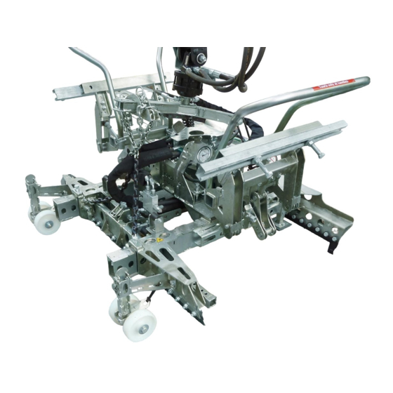
- Page 1 Betriebsanleitung Operating Instructions Instructions d'emploi Hydraulische Verlegezange für den universellen Baggereinsatz Hydraulic Installation Clamps for universal use with excavators Pince hydraulique pour pavés HVZ-ECO DE / GB / FR 5140.0034...
- Page 2 Bitte beachten Sie, dass das Produkt ohne vorliegende Betriebsanleitung in Landessprache nicht eingesetzt / in Betrieb gesetzt werden darf. Sollten Sie mit der Lieferung des Produkts keine Betriebsanleitung in Ihrer Landessprache erhalten haben, kontaktieren Sie uns bitte. In Länder der EU / EFTA senden wir Ihnen diese kostenlos nach.
- Page 4 Betriebsanleitung Original Betriebsanleitung Hydraulische Verlegezange für den universellen Baggereinsatz HVZ-ECO 5140.0034...
-
Page 5: Table Des Matières
Inhalt 2 / 40 Inhalt EG-Konformität ..............................4 Sicherheit ................................5 Definition Fachpersonal / Sachkundiger ......................5 Begriffsdefinitionen ............................5 Sicherheitskennzeichnung ..........................6 Persönliche Sicherheitsmaßnahmen ......................7 Schutzausrüstung ............................7 Unfallschutz ..............................7 Funktions- und Sichtprüfung .......................... 7 2.7.1 Allgemeines ..............................7 2.7.2 Hydraulik .............................. - Page 6 EG-Konformität 3 / 40 Hydraulik ............................... 37 Störungssuche .............................. 38 Reparaturen ..............................39 Prüfungspflicht ............................. 39 Hinweis zum Typenschild ..........................40 Hinweis zur Vermietung/Verleihung von PROBST-Geräten ................ 40 5140.0034...
-
Page 7: Eg-Konformität
Sicherheit von Maschinen - Sicherheitsabstände gegen das Erreichen von Gefährdungsbereichen mit den oberen u. unteren Gliedmaßen (ISO 13857:2008). Dokumentationsbevollmächtigter: Name: J. Holderied Anschrift: Probst GmbH; Gottlieb-Daimler-Str. 6; 71729 Erdmannhausen, Germany Unterschrift, Angaben zum Unterzeichner: Erdmannhausen, 20.12.2017................(M. Probst, Geschäftsführer) 5140.0034... -
Page 8: Sicherheit
Sicherheit 5 / 40 2 Sicherheit Definition Fachpersonal / Sachkundiger Installations, -Wartungs, - und Reparaturarbeiten an diesem Gerät darf nur von Fachpersonal oder Sachkundigen durchgeführt werden! ● Fachpersonal oder Sachkundige müssen für die folgenden Bereichen, soweit für Mechanik es für dieses Gerät zutrifft, die notwendigen beruflichen Kenntnisse besitzen: ●... -
Page 9: Sicherheitskennzeichnung
Sicherheit 6 / 40 Sicherheitskennzeichnung VERBOTSZEICHEN Symbol Bedeutung Bestell-Nr.: Größe: 2904.0210 30 mm Niemals unter schwebende Last treten. Lebensgefahr! 2904.0209 50 mm 2904.0204 80 mm Achtung Quetschgefahr! Nur an Handgriffen anfassen. 2904.0367 205x30 mm WARNZEICHEN Symbol Bedeutung Bestell-Nr.: Größe: 2904.0221 30 mm Quetschgefahr der Hände. -
Page 10: Persönliche Sicherheitsmaßnahmen
Sicherheit 7 / 40 Persönliche Sicherheitsmaßnahmen ● Jeder Bediener muss die Bedienungsanleitung für das Gerät mit den Sicherheitsvorschriften gelesen und verstanden haben. ● Das Gerät und alle übergeordneten Geräte in/an die das Gerät eingebaut ist, dürfen nur von dafür beauftragten und qualifizierten Personen betrieben werden. ●... -
Page 11: Hydraulik
Sicherheit 8 / 40 2.7.2 Hydraulik ● Alle Hydraulikleitungen und Anschlüsse auf Dichtigkeit prüfen. Defekte Teile in drucklosem Zustand von Fachpersonal austauschen lassen. ● Vor dem Öffnen von Hydraulikanschlüssen ist das Umfeld gründlich zu reinigen. Bei Arbeiten an der Hydraulikanlage ist auf Sauberkeit zu achten. ●... -
Page 12: Ermittlung Der Greiftechnischen Qualität
Sicherheit 9 / 40 2.11 Ermittlung der greiftechnischen Qualität Zum sicheren und reibungslosen Betrieb der Anlage/des Gerätes ist es unbedingt erforderlich, dass die Qualität der Steinlagen anhand der folgenden Vorgehensweise durchgeführt wird.: Die Anzahl der zu greifenden Steine wird übereinander Hauptspannungs- gestapelt, wobei die Steine auf der richtung... -
Page 13: Allgemeines
3 Allgemeines Bestimmungsgemäßer Einsatz Die hydraulische Verlegezange HVZ-ECO ist universell geeignet zur Verlegung aller marktüblichen Verbundstein- Verlege-Einheiten in Verbindung mit einem beliebigen Trägergerät (Minibagger, Hydraulikbagger) . Seitens des Trägergerätes (Bagger), sind zwei voneinander getrennte hydraulische Steuerkreise zur Betätigung der HVZ-ECO erforderlich. -
Page 14: Verbundsteinformen
Allgemeines 11 / 40 Verbundsteinformen 1.) Nachstehend abgebildete Verbundsteinformen 1 – 20 sind u. a. für maschinelle Verlegung geeignet. Es können auch andere Steinformen verlegt werden. Voraussetzung ist, dass die Steine in maschinenverlegegerechter Formation paketiert sind. 2.) Die Verbundsteinformen 16-20 sind mit Positionierungsadapter PA (4140.0003) zur maschinellen Verlegung geeignet. - Page 15 Allgemeines 12 / 40 ACHTUNG: Das Arbeiten mit diesem Gerät darf nur in bodennahem Bereich erfolgen. Es dürfen nur Steinelemente mit parallelen und ebenen Greifflächen gegriffen werden! Ansonsten besteht Abrutschgefahr! NICHT ERLAUBTE TÄTIGKEITEN: Eigenmächtige Umbauten am Gerät oder der Einsatz von eventuell selbstgebauten Zusatzvorrichtungen gefährden Leib und Leben und sind deshalb grundsätzlich verboten!! Die Tragfähigkeit und Nennweiten/Greifbereiche des Gerätes dürfen nicht überschritten werden.
-
Page 16: Übersicht Und Aufbau
Technische Daten Hauptspannweite Für Steinhöhe Nebenspannweite = Tragfähigkeit Eigengewicht [mm] [mm] Backenlänge L [mm] [kg] [kg] HVZ-ECO 50-160 ca. 226 960 - 1.440 580 - 1.260 900 – 1.400 600 - 1.200 = Öffnungsweite der Verlegezange Greifbereich (für Steinlagenabmessung) 5140.0034... -
Page 17: Installation
Installation 14 / 40 4 Installation Mechanischer Anbau Die mechanische Verbindung der HVZ-ECO mit dem Trägergerät (Bagger) erfolgt über die eine Baggeraufhängung (UBA, bzw. Lehnhofadapter). Baggeraufhängung Lehnhofadapter Es muss eine gesicherte Verbindung (Steckbolzen mit Sicherungsring) zwischen Drehkopf und Baggeraufhängung hergestellt werden. -
Page 18: Hydraulischer Anbau
Installation 15 / 40 Hydraulischer Anbau Zum Anschluss der HVZ-ECO an das Trägergerät werden zwei voneinander getrennte Hydrauliksteuerkreise benötigt. Der Anschluss der Hydraulikschläuche erfolgt am hydraulischen Drehkopf. Durch Lösen der beiden Arretierungsschrauben kann die Öffnungsweite zwischen der Steckbolzenaufnahme, bei Bedarf verändert werden (). Hierzu beide Steckbolzenaufnahmen herausnehmen, um 180° verdrehen (siehe Pfeile), wieder einführen und mit Arretierungsschraube wieder sichern. - Page 19 Installation 16 / 40 Beim Anschluss der Hydraulikleitungen ist darauf zu achten, dass die Drehrichtung des Trommel, mit der der Drehrichtungsangabe (siehe ) auf dem Gehäuse über einstimmt. Ist dies nicht der Fall, müssen die Anschlüsse überprüft werden. Trommel 5140.0034...
-
Page 20: Einstellung „Bypass-Ventil
Installation 17 / 40 Einstellung „Bypass-Ventil“ Die Nachrüstung eines „Bypass-Ventiles“ (siehe ) am hydraulischen Drehkopf ist erforderlich, um bei Trägergeräten (Baggern) mit Hydrauliköl-Volumenströmen > 40 l/min , einen Teil des Ölstromes gleich wieder in den Rücklauf des Trägergerätes zurück zu leiten. Die optimale Einstellung muss während des laufenden Betriebes der Verlegezange ermittelt werden. -
Page 21: Einstellungen
Einstellungen 18 / 40 5 Einstellungen Allgemein Alle Einstellarbeiten dürfen nur bei stillgelegtem Gerät vorgenommen werden! Vorsicht bei allen Einstellarbeiten besteht Verletzungsgefahr der Hände! Greiftiefeneinstellung Planumseite Greiftiefeneinstellung (Planumseite) ist so einzustellen, Bei extrem großen Steinlagen empfiehlt es sich die dass die Stahllamellen sich im unteren ⅓ der Steinlage Greiftiefeneinstellung etwas niedriger einzustellen, so (siehe Bild 2) befinden. - Page 22 Einstellungen 19 / 40 Federriegel um 180 verdrehen und in Kerbe einrasten. Abstand ca. auf 100 mm -150 mm Mitte Greiftiefeneinstellung entsprechend verschieben u. Greiftiefeneinstellung von der Außenkante der Steinlage Federriegel wieder um 180 verdrehen und einrasten. einstellen (siehe Einstellaufkleber am Gerät). Bild 5 100-150 mm Bild 6...
- Page 23 Einstellungen 20 / 40 Maschinenseite Greiftiefeneinstellung (Maschinenseite) ist so Bei extrem großen Steinlagen empfiehlt es sich die einzustellen, dass die Stahllamellen sich auf der ½ der Greiftiefeneinstellung etwas niedriger einzustellen, so Steinlage (siehe Bild 8) befinden. dass die Stahllamellen im untersten Bereich der Steinlage greifen.
-
Page 24: Einstellung Absetzrollen
Einstellungen 21 / 40 Einstellung Absetzrollen Zum Einstellen der Absetzrollen, beide Höhe der beider Absetzrollen genau gleich einstellen. Federsteckbolzen an den Absetzrollen entfernen. Abstand zwischen Lamellen zur Steinlangenunterkante ungefähr 50 mm (siehe Darstellung A) Bild 11 Bild 12 Beide Absetzrollen wieder mit Federsteckbolzen sichern. -
Page 25: Einstellung Hauptspannung
Einstellungen 22 / 40 Einstellung Hauptspannung Maschinenseite Einstellung „C“ der Hauptspannung laut Hauptspannung auf Position ziehen (). Einstellaufkleber am Gerät (Maschinenseite) Federriegel wieder um 180 verdrehen und einrasten. entsprechend der Steinlagenlänge. Beide Federriegel () um 180 verdrehen und in Kerbe einrasten lassen. - Page 26 Einstellungen 23 / 40 Planumseite Einstellung „A“ und „D“ Hauptspannung laut Klappsplint am Steckbolzen () entfernen und anschließend Steckbolzen entnehmen (siehe Bild Einstellaufkleber (Bild 18) am Gerät (Planumseite) entsprechend der Steinlagenlänge einstellen. 16+17). Planumseite Bild 16 Bild 17 Einstellaufkleber Bild 18 5140.0034...
- Page 27 (siehe Bild 14). Bild 19 Planumseite Das Gerät (HVZ-ECO) ist optimal eingestellt, wenn beim Greifvorgang bei geöffneter Zange, die Stahl-Lamellen (Maschinenseite) direkt an der Steinlage anliegen u. die Stahl-Lamellen (Planumseite) etwa einen Abstand zur Steinlage von 100 -150 mm haben (Bild 20).
-
Page 28: Veränderung Der Backenbreite
Einstellungen 25 / 40 Abdrückschiene Ab einer Steinlagenbreite über 1000 mm sollte die einstellbare Abdrückschiene (max. 1200 mm) ausgefahren werden. Federstecker herausziehen u. gleichzeitig etwas verdrehen. Dann Federstecker wieder los lassen. Abdrückschiene entsprechend verschieben, Federstecker etwas herausziehen u. gleichzeitig etwas verdrehen bis er wieder in Bohrung einrastet. -
Page 29: Einstellung Der Seitenspannung
Einstellungen 26 / 40 Einstellung der Seitenspannung Die Einstellung der Seitenspannung erfolgt durch Zum Einstellen der Einstellschraube muss zuvor die Verstellung der Einstellschraube (auf beiden Seiten an Drehsicherung nach oben geklappt werden. der Seitenspannung) (siehe ) Bild 24 Bild 25 Seitenspannung auf Steinlagenbreite mit Steckschlüssel nach Skalenaufkleber auf beiden Seiten des Gerätes = Vergrößerung der Seitenspannung... -
Page 30: Gewichtsausgleich Einstellen
Bild 28 Bild 29 Gewichtsausgleich einstellen Nach erfolgter Einstellung der Haupt- u. Seitenspannung am Gerät (HVZ-ECO) ist darauf zu achten, dass es waagrecht zur Arbeitsfläche ausgerichtet ist, gegebenenfalls leicht geneigt zur Maschinenseite (Absetzrollen). Klappstecker (C) oben an der Kettenaufhängung (A) entfernen und beide Einstellketten (B) jeweils auf die gleiche Länge einstellen (siehe Bild 30). - Page 31 Einstellungen 28 / 40 Verletzungsgefahr der Hände! 5140.0034...
-
Page 32: Bedienung
Drehkopfbetätigung vertraut. Prägen Sie sich insbesondere ein, welche Hebelfunktion ein Öffnen der Klammer (meist Betätigung des hydraulischen Steuerhebels vom Bediener weg) bewirkt, damit Sie nicht aus Versehen diese Funktion bei angehobener HVZ-ECO mit gegriffener Steinlage betätigen und so die Steinlage aus der Klammer herausfallen lassen. -
Page 33: Programm 2 (Ohne Nebenspannung)
Bedienung 30 / 40 6.1.2 Programm 2 (ohne Nebenspannung) Zum Abgreifen und Verlegen von Steinlagen unter ausschließlicher Verwendung der Hauptspannung. Dieses Programm wird zum Beispiel dann verwendet, wenn bei der Verlegung die Position der Verlegezange zur Steinlage bei jedem zweiten Verlegezyklus um 180 Grad verdreht werden muss. Um Programm 2 zu nutzen, muss der Abstellhahn (unterhalb der Zangenaufhängung) von waagrechter Stellung (Durchflussrichtung) in senkrechte Stellung (Sperrstellung) gestellt werden (siehe Abbildungen darunter). -
Page 34: Hinweise Zur Normgerechten Verlegung Von Betonpflastersteinen
Bedienung 31 / 40 Hinweise zur normgerechten Verlegung von Betonpflastersteinen ● Es wird davon ausgegangen, dass die zur Verlegung kommenden Betonstein- Verlegeinheiten eine normgerechte, gleichförmiges Verlegemuster erlauben. ● Es wird davon ausgegangen, dass die zur Verlegung kommenden Betonpflastersteine mit sogenannten Abstandshilfen mit mindestens 2,5 mm Dicke versehen sind. -
Page 35: Ablauf Des Verlege-Zyklus
Trägergerätes und Anbaugerätes im Sichtfeld haben und sicherstellen, dass sich weder Personen noch Gegenstände im Gefahrenbereich befinden. ● Anheben der HVZ-ECO mittels des Trägergerätes, bis die Zange frei hängt. ● Reset-Vorgang der HVZ-ECO durchführen: Hydraulischen Steuerhebel des Trägergerätes (Bagger) auf „Position 1“ (siehe Bild 3) betätigen und solange in dieser Position halten, bis die ADV-Federn komplett zusehen sind (siehe ... - Page 36 ● Die Klammer absenken, bis die Auflageteller der Klammer die Steinoberflächen berühren. Danach nicht weiter absenken! Die Traverse darf keinesfalls den HVZ-ECO Aufsatz berühren und somit Druck von oben auf die Klammer ausgeübt werden (durch den Ausleger des Trägergerätes). ●...
-
Page 37: Allgemeine Hinweise Zur Normgerechten Verlegung
Bedienung 34 / 40 ● In frei hängendem Zustand der Klammer den Steuerhebel wiederholt auf „Pos. 1“ betätigen und dort so lange halten, bis die Hauptspannung ganz geöffnet ist und der Abdrückzylinder ausgefahren wurde. TIPP: Diese Klammerbetätigung kann zur Zeiteinsparung auch während des Zurückschwenkens der Klammer zur Erneuten Aufnahme der nächsten Steinlage erfolgen. -
Page 38: Allgemeine Hinweise Zur Verlegung
Bedienung 35 / 40 Allgemeine Hinweise zur Verlegung: ● Der hohe Mechanisierungsgrad der maschinellen Verlegung lässt sich nur wirtschaftlich optimieren, wenn die Randbedingungen ebenfalls optimiert werden. Da eine Verbundsteinverlegung zu einem großen Teil aus Transport und nur zu einem relativ kleinen Teil aus dem eigentlichen Verlegevorgang besteht, ist klar, dass der Transport auf der Baustelle optimiert werden muss. - Page 39 Bedienung 36 / 40 ● Bänder immer 2-seitig, möglichst weit unten am Paket abschneiden, um unbeabsichtigtes Einklemmen der Bänder beim Abgreifen mit der Verlegezange zu verhindern. Wenn dies geschieht, wird oft der Fugenverband auf der Palette verschoben, und es muss manuell korrigiert werden. ●...
-
Page 40: Wartung Und Pflege
Wartung und Pflege 37 / 40 7 Wartung und Pflege Wartung Um eine einwandfreie Funktion, Betriebssicherheit und Lebensdauer des Gerätes zu gewährleisten, sind die in der Tabelle aufgeführten Wartungsarbeiten nach Ablauf der angegebenen Fristen durchzuführen. Es dürfen nur Original-Ersatzteile verwendet werden; ansonsten erlischt die Gewährleistung. Alle Arbeiten dürfen nur in drucklosem, stromlosen und bei stillgelegtem Zustand des Gerätes erfolgen! Bei allen Arbeiten muss sichergestellt sein, dass sich das Gerät nicht unabsichtlich schließen kann. -
Page 41: Störungssuche
Wartung und Pflege 38 / 40 Störungssuche STÖRUNG URSACHE BEHEBUNG ● ● Steinlage bricht nach unten aus Hauptspannung ist falsch Einstellung nach Einstellaufkleber eingestellt (200 mm Hub) überprüfen ● ● Steinlage ist extrem groß Greiftiefe etwas tiefer einstellen, dass Stahllamellen im unteren Bereich der Steinlage greifen. -
Page 42: Reparaturen
Wartung und Pflege 39 / 40 Reparaturen Reparaturen am Gerät dürfen nur von Personen durchgeführt werden, die die dafür notwendigen Kenntnisse und Fähigkeiten besitzen. Vor der Wiederinbetriebnahme muss eine außerordentliche Prüfung durch einen Sachverständigen durchgeführt werden. Prüfungspflicht Der Unternehmer hat dafür zu sorgen, dass das Gerät mindestens jährlich durch einen Sachkundigen geprüft und festgestellte Mängel sofort beseitigt werden (... -
Page 43: Hinweis Zum Typenschild
Kettenzug, Gabelstapler, Bagger...) mit zu berücksichtigen. Beispiel: Hinweis zur Vermietung/Verleihung von PROBST-Geräten Bei jeder Verleihung/Vermietung von PROBST-Geräten muss unbedingt die dazu gehörige Original Betriebsanleitung mitgeliefert werden (bei Abweichung der Sprache des jeweiligen Benutzerlandes, ist zusätzlich die jeweilige Übersetzung der Original Betriebsanleitung mit zuliefern)! - Page 44 Anleitung zur Einstellung der Hydraulischen Verlegezange HVZ-ECO Zange & Zubehör Version A Version B Steinlage nicht verschoben. Steinlage nicht verschoben. Soll mit Zange verschoben werden Soll mit Zange so verlegt werden. 1200 mm + halber Stein = 1300 mm *...
- Page 45 Einstellung der Hauptspannung (für Version A + B) Vorderseite Vorderseite *Siehe Bilder Version A Einstellung der Seitenspannung 800* Seite 1 = 400 mm (für Version A + B) Version B Version A 1200 mm 1300 mm Vorderseite Vorderseite Siehe Bilder Version A Seite 1 + 100 = 500 mm...
- Page 46 Montage der Halfeneisen Montage der Positionsadapter (für Version A + B) (nur für Version A) 2 x (beidseitig) versetzt kürzen, oder passende Länge bestellen Linke Linke Seite Seite ✓ Rechte Rechte Seite Seite...
- Page 47 Einstellung der Greifh öhe Höhenverstellung (für Version A + B) (für Version A + B) Rückseite Rückseite mittig Abdrückvorrichtung (A + B) Rückseite Rückseite mittig Absetzrollen (A + B) Vorderseite Vorderseite Vorderseite Vorderseite 2 – 4 mm im unteren Drittel...
- Page 48 2. Die Verbundsteinformen 16 – 20 sind mit Positionierungsadapter PA zur maschinellen Verlegung geeignet. 3. Die Verbundsteinformen 21 – 25 sind mit Sonderadapter zur maschinellen Verlegung geeignet. Probst GmbH • Gottlieb-Daimler-Str. 6 • 71729 Erdmannhausen • Tel. +49 7144 3309-0 • Fax +49 7144 3309-50 • info@probst-handling.de • www.probst-handling.de...
- Page 49 (durch eine autorisierte Fachwerkstatt)! Nach jeder erfolgten Durchführung eines Wartungsintervalls muss unverzüglich dieser Wartungsnachweis (mit Unterschrift u. Stempel) an uns übermittelt werden 1). 1) per E-Mail an: service@probst-handling.com / per Fax oder Post Betreiber: _ _ _ _ _ _ _ _ _ _ _ _ _ _ _ _ _ Gerätetyp:...
- Page 53 Operating Instructions Translation of original operating instructions Hydraulic Installation Clamps for universal use with excavators HVZ-ECO 51400034...
- Page 54 Inhalt 2 / 41 1 Contents Contents ................................. 2 EC-Declaration of Conformity ..........................4 Safety ..................................5 Definition skilled worker / specialist ......................5 Explanation of basic concepts ........................5 Safety symbols ..............................5 Safety Marking ..............................6 Personal safety requirements ........................7 Protective equipment.............................
- Page 55 Maintenance and care ............................38 Maintenance ..............................38 MECHNICAL ..............................38 HYDRAULIC ..............................38 Troubleshooting ............................39 Repairs ................................40 Safety procedures ............................40 Hints to the type plate ..........................40 Hints to the renting/leasing of PROBST devices ..................41 51400034...
-
Page 56: Ec-Declaration Of Conformity
Safety of machinery ― Safety distances to prevent hazard zones being reached by upper and lower limbs (ISO 13857:2008) Authorized person for EC-dokumentation: Name: J. Holderied Address: Probst GmbH; Gottlieb-Daimler-Str. 6; 71729 Erdmannhausen, Germany Signature, informations to the subscriber: Erdmannhausen, 20.12.2017................(M. Probst, Managing director) -
Page 57: Safety
Safety 5 / 41 3 Safety Definition skilled worker / specialist Only skilled workers or specialists is it allowed to carry out the installation,- maintenance, - and repair work on these device! ● Skilled workers or specialists must have for the following points (if it applies for for mechanic ●... -
Page 58: Safety Marking
Safety 6 / 41 Safety Marking PROHIBITION SIGN Symbole Meaning Order-No Size: 2904.0210 30 mm It is not allowed to be under hanging loads. Danger to life! 2904.0209 50 mm 2904.0204 80 mm Caution! Danger of squeezing! Touch only at handles. 2904.0367 205x30 mm WARNING SIGN... -
Page 59: Personal Safety Requirements
Safety 7 / 41 Personal safety requirements ● Each operator must have read and understood the operating instructions. ● Only qualified, authorized personal is allowed to operate the device and all devices which are connected (lifting equipment). ● The manual guiding is only allowed for devices with handles. Protective equipment ●... -
Page 60: Hydraulic
Safety 8 / 41 3.3.2 Hydraulic ● Check all hydraulic hoses and connection for tightness. Only experts are allowed to replace faulty parts (depressurized) ● Ensure a clean working environment before opening the hydraulic connection. ● The hydraulic hoses must be free of breaks and abrasion. Take care that there are no outstanding edges, where the hoses could hook in. -
Page 61: Check On The Gripping Quality Of Certain Layers Of Paving Stones
Safety 9 / 41 3.5.2 Check on the gripping quality of certain layers of paving stones For the secure function of the automatic cuber/the device the gripping quality of certain layers of paving stones has to be checked as follows: Take the number of blocks you want to grip, the blocks in main gripper direction have to face the ground. -
Page 62: General
This Hydraulic Installation Clamp HVZ-ECO was developed to meet the need of builders for a device to mechanically install a wide range of pavers which are delivered to the site in ready-to-install formation. The HVZ-ECO may be used in connection with any carrier (mini-excavator, hydraulic excavator, wheel loader) . -
Page 63: Stone Formations
General 11 / 41 Stone formations 1.) The stone formations 1 – 20 shown below are suitable among others for mechanical installation. Other stone formations can also be laid by machines as long as the stones are packed in the correct formation ready for the machine to lay them. - Page 64 General 12 / 41 ATTENTION: The use of this device is only permitted in proximity to the ground. Only stone elements with parallel and plane surface are allowed to be picked-up and handled. Because the gripping good could fall down. NOT ALLOWED AKTIVITIES: Unauthorized alterations of the device and the use of any self-made additional equipment could cause danger and are therefore forbidden!!
-
Page 65: Survey And Construction
Side clamping Technical data Main gripping width Gripping depth Side gripping width Carrying capacity/working Dead weight Type load limit (WLL) HVZ-ECO 50-160 mm 400 kg ca. 210 kg 580 - 1.260 mm 960 - 1,400 mm (2“-6¾“) (880 lbs) (approx. 460 lbs) (22¾... -
Page 66: Installation
Installation 14 / 41 5 Installation Mechanical connection The mechanical connection of the HVZ –ECO at the support frame (excavator) takes place with the universal- excavator-suspension (UBA or Lehnhofadapter). Excavator-suspension - Lehnhofadapter Make a secure connection (bolt with locking ring) between the rotating head and the excavator-suspension. -
Page 67: Hydraulical Connection
Installation 15 / 41 Hydraulical connection Two separate hydraulic circuit are required to connect the HVZ-ECO to the support frame The connection of the hydraulic hoses takes place on the hydraulic rotator. The opening width between the bolt sockets can be adjusted ( ) by loosening of the locking screws. - Page 68 Installation 16 / 41 When connecting the hydraulic lines, look after the rotating direction of the drum, that it is identical to the rotating direction at the casting (see ). If this is not the case, the connections must be changed. Drum 51400034...
-
Page 69: Adjustment „Bypass-Valve
Installation 17 / 41 Adjustment „Bypass-Valve“ The retrofitting of a so-called „bypass valve“ on the hydraulic rotator is necessary to pass one part of oil to the return flow of the support device, when the volume flow rate is above 40 l/min. The optimal adjustment has to be made during actual operation of the installation clamp. - Page 70 Adjustments 18 / 41 6 Adjustments General For all operations you have to make sure, that the device will not close unintended. Danger of injury!!! Caution with all adjustments exists danger of injury the hands! Adjustments of the feather-steel-lamellas ● The feather-steel-lamellas should not stitch out sideways over the contur of the laying cluster, because they could hit the already laid blocks when laying a new cluster into...
-
Page 71: Adjustments
Adjustments 19 / 41 General For all adjustments the device must be completely shut down! Caution with all adjustments exists danger of injury the hands! 6.3.1 Adjusting the gripping depth Facing bedding sand (planum) Adjust the gripping depth (laying side) so, that the steel- With extremely large stone layers it recommends to ⅓... - Page 72 Adjustments 20 / 41 Pull the spring bolt upwards, rotate around 180° and Adjust the gripping depth distance approx. on 100mm - lock in position (in nick). 150 mm from the middle of the gripping depth to the outside edge of the stone layer (see stickers at the Adjust gripping depth and rotate the spring bolt again device).
- Page 73 Adjustments 21 / 41 Machine Side Adjust the gripping depth (machine side) so, that the With extremely large stone layers it recommends to adjust the gripping depth a little lower, so that the steel- ½ steel-lamellas are gripping in the of the stone layer lamellas grip in the lowest range of the stone layer.
-
Page 74: Height Adjustment Of The Rollers
Adjustments 22 / 41 Height adjustment of the rollers Remove the spring cotter pins to adjust the height of Adjust the height of both rollers identically. the rollers. Distance between the steel lamellas to the lower edge of the stone layer ~ 50 mm (see picture A ) Fig. -
Page 75: Adjustment Main Clamping
Adjustments 23 / 41 Adjustment main clamping Machine Side Adjust adjusting „C“ at the main gripping corresponding Pull main gripping in the corresponding position (). to the length of the stone layer see sticker at the Rotate the spring bolt again around 180° and lock in device (machine side). - Page 76 Adjustments 24 / 41 Facing bedding sand (Planum) Adjust the adjusting „A“ und „D“ at the main gripping Remove safety clip at the bolt (see Fig. 16+17). corresponding to the length of the stone layer see adjustment sticker at the device (laying side). Planumseite Fig.
- Page 77 Fig. 19 Planumseite The device (HVZ-ECO) is optimally adjusted, if during the gripping procedure with opened device the steel lamellas (machine side) contact directly on the stone layer and when the steel lamellas (laying side) have distance to the stone layer of 100 -150 mm. (Fig. 20).
-
Page 78: Extension Of The Gripper Width
Adjustments 26 / 41 ushing-off bar With a stone layer breadth over 1000 mm the adjustable pushing-off bar (max. 1200 mm) should be extended. Pull out the spring plug and rotate it a little at the same time. Then let spring plug go. Then move the spring plug corresponding to the stone layer breadth. -
Page 79: Adjustment Of The Side Gripping
Adjustments 27 / 41 Adjustment of the side gripping Adjust side clamping (see on the left and on the right at Move the rotary protection upwards before adjusting the side gripping side of the device ) with the the adjusting screw. adjusting screws. - Page 80 Adjustments 28 / 41 Adjusting the side clamping corresponding to the stone layer breadth with a socket key Fig 27. = Enlargement of the side clamping The adjusting must have the same value at the left and right side (orientation on adjusting scale Fig 26). = Reduction of the side clamping Then move the rotary protection downwards to secure the side clamping (see Fig.
-
Page 81: Adjustment Weight Balance
29 / 41 Adjustment weight balance When the adjusting of the main- and side clamping is finished, mind, that the device (HVZ-ECO) hangs horizontal to the working area. If required a little tilled to the machine side (rollers). Remove the linchpin (C) at the chain suspension (A), then adjust both adjusting chains (B) to the same length (see Fig. - Page 82 ● With the careful handling, the HVZ-ECO-Easy can also be used to gets empty pallets out of the way - to pile up (for the lately) rational transportation. However, it must be strictly ensured, that the pallets are not gripped with the full clamping pressure of the main clamping.
-
Page 83: Operation
Activate the control lever as possible at idling speed of the support frame. ● Move the operating lever almost at idling speed, because the great hydraulic flows of big excavators can cause malfunctions or even damages of the HVZ-ECO. 7.1.1 Programms In this program version the following programs are stored: ●... - Page 84 Program 2: „without side clamping“, for the gripping and laying of stone pavers only with the main clamping. This program will be used, when rotating the position at 180° at every second laying cycle of the HVZ-ECO to the stone layer.
-
Page 85: Indications For Concrete Paver Installation, Complying With The Standards
Operation 33 / 41 Indications for concrete paver installation, complying with the standards ● It is assumed that the concrete paving stone installation units (layers of pavers), which are to be laid, comply with the requirements allowing a uniform laying pattern, complying with the standards. ●... -
Page 86: Operating Procedure Of Laying Cycle
He must ensure, that in the danger zone are either persons nor objects ● Lifting up the HVZ-ECO using the support frame till the clamp is hanging free. ● RESET procedure of the HVZ-ECO accomplish: ●... - Page 87 ● Position the HVZ-ECO over the stone layer, which shall be gripped. ● Turn the HVZ-ECO in such a way by means of the hydraulic rotator that it can be lowered over the stone layer which can be gripped. ●...
-
Page 88: General Hints For Laying According To Standards
Operation 36 / 41 The laying cycle is finally finished, when the springs of the ADV (see in fig.1 ) are complete visible. Fig. 1 General hints for laying according to standards After the laying process is done it is necessary to move the new laid paving stones a little bit in direction of the facing bedding sand (the best way for the operating personal is to use his feet). -
Page 89: General Laying-Hints
Operation 37 / 41 General laying-hints: ● To optimize the high degree of mechanization in the mechanical paver laying it is necessary t optimize the boundary conditions. Because the laying process consists in majority of transportation and the process of paving is the smaller part it is evident to optimize the transportation on the building ground. -
Page 90: Maintenance And Care
Maintenance and care 38 / 41 8 Maintenance and care Maintenance To ensure the correct function, safety and service life of the device the following points must be executed in the maintenance interval. Used only original spare parts, otherwise the warranty expires. All operations may only be made in unpressurised, electro less and closed state of the device! For all operations you have to make sure, that the device will not close unintended. -
Page 91: Troubleshooting
Maintenance and care 39 / 41 Troubleshooting ERROR CAUSE REPAIR ● ● Stone layer breaks out (downward) Main clamping is wrong Check the adjustments according adjusted (stroke 200 mm) to the adjustment sticker ● ● Stone layer is too large Adjust the gripping depth a little lower, so that the steel lamellas grip in the lower range of the... -
Page 92: Repairs
Maintenance and care 40 / 41 Repairs ● Only persons with the appropriate knowledge and ability are allowed to repair the device. ● Before the device is used again, it has to be checked by an expert. Safety procedures It is the contractors responsibility to ensure that the device is checked by an expert in periods of max. -
Page 93: Hints To The Renting/Leasing Of Probst Devices
Example: Hints to the renting/leasing of PROBST devices With every renting/leasing of PROBST devices the original operating instructions must be included unconditionally (in deviation of the users country's language, the respective translations of the original operating instructions must be delivered additionally)! - Page 94 Instructions for setting the Hydraulic Installation Clamp HVZ-ECO Clamp & Accessories Version A Version B Layer of stones not shifted. Layer of stones not shifted. Have to be shifted with the clamp Should be installed with the clamp. 1,200 mm + half paver = 1,300 mm *...
- Page 95 Adjusting the main gripping width (for Version A + B) Front Front *See pictures Version A Adjusting the side grippers 800* page 1 = 400 mm (for Version A + B) Version B Version A 1200 mm 1300 mm Front See pictures Version A page 1...
- Page 96 Assembly of the C-Profi les Assembly of the positioning (for Version A + B) adapters (only for Version A) 2 x (on both sides) vice versa Cut or order suitable length Left Left side side ✓ Right Right side side...
- Page 97 Adjusting the gripping height Height adjustment (for Version A + B) (for Version A + B) Back Back middle Pushing Off Device ADV (A + B) Back middle Supporting wheels (A + B) Front Front Front 2 – 4 mm in the lower in the lower third...
- Page 98 2. The stone formations 16 – 20 are suitable for mechanical installation by the special adapter. 3. The stone formations 21 – 25 are suitable for mechanical installation by special adapter. Probst GmbH • Gottlieb-Daimler-Str. 6 • 71729 Erdmannhausen • Phone +49 7144 3309-0 • Fax +49 7144 3309-50 • info@probst-handling.de • www.probst-handling.com...
- Page 99 After each completed performance of a maintenance interval the included form must be fill out, stamped, signed and send back to us immediately 1) via e-mail to service@probst-handling.com / via fax or post Operator: _ _ _ _ _ _ _ _ _ _ _ _ _ _ _ _ _...
- Page 101 Instructions d'emploi Traduction des instructions d'emploi originales Pince hydraulique pour pavés HVZ-ECO HVZ-ECO 5140.0034...
- Page 102 Description: 2 / 41 Sommaire CE-Déclaration de Conformité ..........................4 Sécurité ................................... 5 Définition personnel spécialisé / expert ......................5 Définitions ............................... 5 Instructions de sécurité ..........................5 Mesures de sécurité personnelle ........................7 Equipment de protection ..........................7 Protection contre les accidents ........................7 Essai de fonctionnement et inspection visuelle ....................
- Page 103 Maintenance ..............................38 7.1.1 Mechanique ..............................38 7.1.2 Hydraulique .............................. 39 Élimination des dérangements ........................39 Réparations ..............................40 Devoir de contrôle ............................40 Informations concernant la plaque signalétique ..................41 Remarque concernant la location/le prêt des engins PROBST ..............41 5140.0034...
-
Page 104: Ce-Déclaration De Conformité
Sécurité des machines ― Distances de sécurité empêchant les membres supérieurs et inférieurs d'atteindre les zones dangereuses. Personne autorise pour EC-documentation: Nom: J. Holderied Adresse: Probst GmbH; Gottlieb-Daimler-Straße 6; 71729 Erdmannhausen, Germany Signature, informations ou signataire: Erdmannhausen, 18.03.2019................(Martin. Probst, Gérant) -
Page 105: Sécurité
Sécurité 5 / 41 Sécurité Définition personnel spécialisé / expert Les travaux d’installation, de maintenance et de réparation sur cet appareil doivent être effectués uniquement par du personnel spécialisé ou des experts. • Dans la mesure où cela concerne cet appareil, le personnel spécialisé ou les en mécanique experts doivent posséder les connaissances professionnelles requises dans les •... - Page 106 Sécurité 6 / 41 Signalisation de sécurité PANNEAUX D’INTERDICTION Symbole Signification Réf. Taille 2904.0210 30 mm Ne jamais se placer sous une charge suspendue. Danger de mort ! 2904.0209 50 mm 2904.0204 80 mm Attention: Risque d’écrasement des mains.! Le guidage manuel de l’appareil n’est autorisé que si celui-ci est 2904.0367 205x30 mm tenu par les poignées.
-
Page 107: Mesures De Sécurité Personnelle
Sécurité 7 / 41 Robinet d’arrêt pour le serrage secondaire (si seule la tension 2904.0643 95x50 mm principale est utilisée). Toutes les pinces de transport doivent être déverrouillées avant 2904.0630 92x35 mm la mise en service de l'appareil (optionelles) Mesures de sécurité personnelle •... -
Page 108: Essai De Fonctionnement Et Inspection Visuelle
Sécurité 8 / 41 Essai de fonctionnement et inspection visuelle 2.7.1 Généralités • Le fonctionnement et l'état de l'appareil doivent être vérifiés avant chaque utilisation. • N’effectuez l‘entretien, le graissage et la remise en état de l’engin que lorsque celui-ci est à l’arrêt ! •... -
Page 109: Sécurité Pendant La Pos
Sécurité 9 / 41 2.8.2 Sécurité pendant la pos • Tirer l'appareil en position uniquement par ses poignées ! • L'opérateur doit pouvoir observer l'appareil sans entrave pendant la totalité du transport jusqu'à la dépose. • Ne jamais saisir les couches de pavés de manière excentrée, risque de basculement et de blessures ! •... -
Page 110: Détermination De La Qualité Technique De Préhensionx
Sécurité 10 / 41 2.8.3 Détermination de la qualité technique de préhensionx Pour assurer un fonctionnement en toute sécurité et sans perturbation de l’unité, il est absolument nécessaire que la qualité des couches de pavés soit contrôlée selon la méthode suivante : Empiler le nombre de pavés à... -
Page 111: Généralités
Utilisation conforme • La pince hydraulique à pavés HVZ-ECO est un outil universel destiné à la pose de toutes les unités de pose de pavés usuelles du marché en association avec différents appareils porteurs tels par exemple tout type d’excavatrice (mini- pelle, pelle hydraulique). -
Page 112: Set D'accessoires
Généralités 12 / 41 3.1.1 Set d'accessoires: Clé à douille pour le réglage de la tension latérale (7063.0001) Clé Allen SW08 pour le déplacement du rail adaptateur de position (7063.0001) Tôles d'acier à ressort pour élargir la largeur de la mâchoire à la tension principale (34010100) Tôles d'acier à... - Page 113 Généralités 13 / 41 • L’appareil ne peut être utilisé que pour l’usage prévu dans la notice d’instructions, en respectant les règles de sécurité en vigueur, ainsi que les dispositions correspondantes de la déclaration de conformité. • Tout autre usage est considéré comme non conforme à l’usage prévu et est interdit ! •...
-
Page 114: Vue D´ensemble Et Structure
Caractéristiques techniques Type Ecartement Hauteur de Ecartement secondaire Charge admissible Poids propre principal pavé** HVZ-ECO 50-160 mm 400 kg ca. 227 kg 580 - 1.260 mm 960 - 1.440 mm 600 - 1.200 mm 900 – 1.400 mm = Largeur d'ouverture de la pince de pose = Plage de préhension (pour les dimensions de la couche de brique... -
Page 115: Installation
La mort, des blessures graves et des dommages matériels peuvent en être la conséquence. L’assemblage mécanique entre la HVZ-ECO et l’appareil porteur (excavatrice) est réalisé au moyen d’un dispositif de fixation sur excavatrice (UBA, ou adaptateur de type Lehnhof). - Page 116 Installation 16 / 41 Dispositif de fixation UBA Il faut réaliser un assemblage sécurisé (vis de blocage avec écrou et contre-écrou supplémentaire) entre la tête pivotante et le dispositif de fixation sur l’excavatrice. Dispositif de fixation sur excavatrice (UBA) Vis de blocage avec écrou (+contre-écrou) ...
-
Page 117: Fourreaux (En Option)
Installation 17 / 41 4.1.1 Fourreaux (en option) • Afin d’assurer une liaison entre le chariot élévateur et le fourreau, il faut introduire les fourches du chariot dans les fourreaux et les bloquer, soit par l’intermédiaire de vis de blocage positionnées dans un perçage à... -
Page 118: Montage Hydraulique En Annexe À Une Unité De Base
18 / 41 Montage hydraulique en annexe à une unité de base Deux circuits hydrauliques séparés sont nécessaires pour raccorder la HVZ-ECO à l’appareil porteur. Les tuyaux hydrauliques sont raccordés au niveau de la tête pivotante hydraulique. La largeur d’ouverture entre le porte-cheville peut être modifiée si nécessaire en desserrant les deux vis de blocage (). - Page 119 Installation 19 / 41 Lors du branchement des conduites hydrauliques, il faut veiller à ce que le sens de rotation du tambour corresponde au sens de rotation affiché sur le boîtier (voir ) Dans le cas contraire, il faut vérifier les branchements. Tambour Réglage „by-pass de vanne Le montage a posteriori d'une "soupape de dérivation"...
-
Page 120: Réglage
Réglage 20 / 41 Réglage Généralités Tous les travaux de réglage doivent obligatoirement être réalisés sur un appareil à l’arrêt ! Soyez prudent lorsque vous effectuez des réglages. Risque de blessures aux mains. Porter des gants de protection. → Réglage de la profondeur de préhension 5.2.1 Côté... - Page 121 Réglage 21 / 41 Ill. 3 Ill. 4 Faire pivoter le verrou á ressort de 180 et bloquer dans Régler un intervalle de 100mm à 150 mm env. entre le l’encoche. centre du dispositif de réglage de la profondeur de Décaler le dispositif de réglage de la profondeur de préhension et le bord extérieur de la couche de pavés préhension et tourner à...
-
Page 122: Côté Machine
Réglage 22 / 41 5.2.2 Côté machine Lorsque les surfaces de pavés sont très grandes, la profondeur La profondeur de préhension (côté machine) doit être de préhension devrait être légèrement décalée vers le bas afin réglée de façon à ce que les lamelles en acier se situent que les lamelles soient en contact dans la partie inférieure de la à... -
Page 123: Réglage Des Galets De Pose
Réglage 23 / 41 Réglage des galets de pose Pour régler les galets de pose retirez les deux axes des La hauteur des deux galets doit être exactement rouleaux d'abaissement. identique. Intervalle de 50 mm environ entre les lamelles et le bord inférieur de la couche de pavés (voir schéma A) Ill. -
Page 124: Réglage Du Serrage Principal
Réglage 24 / 41 Réglage du serrage principal 5.4.1 Côté machine Réglage „C“ du serrage principal conformément à Régler la position du serrage principal (). l’autocollant de réglage sur l’appareil (côté machine) en Tourner à nouveau le verrou à ressort de 180, bloquer. fonction de la longueur de la couche de pavés. -
Page 125: Côté Terrain
Réglage 25 / 41 5.4.2 Côté terrain Réglage „A“ et „D“ du serrage principal conformément Retirez la goupille fendue de la goupille de la douille (), puis enlevez la goupille (voir Figs. 16+17). à l’autocollant de réglage sur la machine (côté terrain) en fonction de la longueur de la couche de pavés (voir Ill. - Page 126 Ill. 19 Côté terrain Le réglage de l’appareil (HVZ-ECO) est optimal si, pendant l’opération de préhension, lorsque la pince est ouverte, les lamelles en acier (côté machine) sont directement appliquées contre la couche de pavés et si les lamelles en acier (côté...
-
Page 127: Barre De Maintien
Réglage 27 / 41 Barre de maintien Lorsque la largeur de la couche de pavés est supérieure à 1000 mm, il est conseillé d’utiliser la barre de maintien réglable (max. 1200 mm). Tirer et tourner simultanément la goupille à ressort. Relâcher ensuite la goupille à... -
Page 128: Agrandissement Des Mâchoires De Serrage
Réglage 28 / 41 5.6.1 Agrandissement des mâchoires de serrage Pour une préhension optimale des couches de pierre, il est possible de modifier la largeur de la mâchoire en conséquence. Motif : parce que les plaques extérieures en acier à ressorts (fig. - Page 129 Réglage 29 / 41 Réglez la tension latérale sur la largeur de la couche de pierres à la même valeur des deux côtés de la machine à = augmenter le ecartement secondaire l'aide d'une clé à douille selon l'autocollant de l'échelle graduée (voir Fig.
-
Page 130: Réglage De La Compensation De Poids
Réglage 30 / 41 Réglage de la compensation de poids Une fois que le réglage du serrage principal et secondaire est terminé sur l’appareil (HVZ-GENIUS), il faut faire attention à ce que l’appareil soit horizontal par rapport à la surface de travail, si nécessaire il peut être légèrement incliné... -
Page 131: Maniement
Mémorisez notamment la fonction du levier qui provoque l'ouverture de la tension principale, afin de ne pas l'actionner par inadvertance lorsque la HVZ-ECO est soulevée et faire chuter la couche de pavés des griffes. - Page 132 Maniement 32 / 41 Programme 2 : „Sans serrage secondaire“, pour saisir et poser des couches de pavés en utilisant exclusivement le serrage principal. Ce programme est utilisé par exemple lorsque la position de la pince par rapport à la couche de pavés doit être modifiée de 180 degrés à...
-
Page 133: Remarques Sur La Pose De Pavés En Béton Conformément Aux Normes
Maniement 33 / 41 Remarques sur la pose de pavés en béton conformément aux normes • On suppose que les unités de pose de pavés en béton à poser permettent un modèle de pose de forme égale, conforme aux normes. •... -
Page 134: Déroulement Du Cycle De Pose
Le conducteur du véhicule porteur doit voir à tout moment l'ensemble de la zone de travail de l'appareil porteur et de l'appareil de pose et garantir qu'aucune personne ou objet se trouve dans la zone dangereuse. • - Soulevez le HVZ-ECO à l'aide du support jusqu'à ce que l'appareil soit suspendu librement. • Reset-Vorgang der HVZ-ECO durchführen: •... - Page 135 Maniement 35 / 41 • Pivoter la pince pour la positionner au dessus de la couche de pavés à saisir ● A l’aide de la tête pivotante hydraulique, tourner la pince afin de pouvoir la faire descendre au dessus de la couche de pavés à...
-
Page 136: Remarques Générales Sur La Pose Conforme Aux Normes
Maniement 36 / 41 CONSEIL : Pour gagner du temps, cette manoeuvre peut également être exécutée pendant le retour de la pince pour saisir la couche de pavés suivante. Le cycle de pose est maintenant terminé, la pince est prête pour soulever la couche de pavés suivante. Le cycle de pose est complètement terminé... - Page 137 Maniement 37 / 41 • La solution optimale consiste en une livraison "juste à temps", afin de faire positionner les paquets de pavés par la grue de déchargement toujours aussi près que possible de l'arête de pose qui avance. • Prévoir dans tous les cas une distance des paquets de tous les côtés suffisamment grande pour que le préhenseur à...
-
Page 138: Maintenance Et Entretien
Maintenance et entretien 38 / 41 Maintenance et entretien Maintenance Pour que l´appareil fonctionne parfaitement, pour assurer sa sécurité de fonctionnement et une longue durée de vie, il est impératif d’effectuer les opérations de maintenance spécifiées dans le tableau ci-dessous aux intervalles prescrits. -
Page 139: Hydraulique
Maintenance et entretien 39 / 41 7.1.2 Hydraulique Délai d’entretien Opérations à effectuer Première inspection après • Contrôler et resserrer, le cas échéant, tous les raccords hydrauliques (opération à 25 heures de service : effectuer par un expert). Toutes les 50 heures de travail •... -
Page 140: Réparations
• Observer les prescriptions correspondantes des associations professionnelles déclaration de conformité. • Le contrôle expert peut également être effectué par le fabricant Probst GmbH. Contactez-nous à : service@probst-handling.com • Lorsqu’un contrôle a été effectué et que les déficiences ont été réparées sur l´appareil, nous conseillons d’apposer la plaquette „CONTRÔLE DE SÉCURITÉ“... -
Page 141: Informations Concernant La Plaque Signalétique
Exemple: Remarque concernant la location/le prêt des engins PROBST Lors de chaque location/prêt d’un engin PROBST, les instructions d’emploi originales correspondantes doivent impérativement être jointes (si la langue n’est pas celle de l’utilisateur, une traduction des instructions d’emploi originales dans la langue adéquate doit être fournie) ! - Page 142 Anleitung zur Einstellung der Hydraulischen Verlegezange HVZ-ECO Zange & Zubehör Version A Version B Steinlage nicht verschoben. Steinlage nicht verschoben. Soll mit Zange verschoben werden Soll mit Zange so verlegt werden. 1200 mm + halber Stein = 1300 mm *...
- Page 143 Einstellung der Hauptspannung (für Version A + B) Vorderseite Vorderseite *Siehe Bilder Version A Einstellung der Seitenspannung 800* Seite 1 = 400 mm (für Version A + B) Version B Version A 1200 mm 1300 mm Vorderseite Vorderseite Siehe Bilder Version A Seite 1 + 100 = 500 mm...
- Page 144 Montage der Halfeneisen Montage der Positionsadapter (für Version A + B) (nur für Version A) 2 x (beidseitig) versetzt kürzen, oder passende Länge bestellen Linke Linke Seite Seite ✓ Rechte Rechte Seite Seite...
- Page 145 Einstellung der Greifh öhe Höhenverstellung (für Version A + B) (für Version A + B) Rückseite Rückseite mittig Abdrückvorrichtung (A + B) Rückseite Rückseite mittig Absetzrollen (A + B) Vorderseite Vorderseite Vorderseite Vorderseite 2 – 4 mm im unteren Drittel...
- Page 146 2. Die Verbundsteinformen 16 – 20 sind mit Positionierungsadapter PA zur maschinellen Verlegung geeignet. 3. Die Verbundsteinformen 21 – 25 sind mit Sonderadapter zur maschinellen Verlegung geeignet. Probst GmbH • Gottlieb-Daimler-Str. 6 • 71729 Erdmannhausen • Tel. +49 7144 3309-0 • Fax +49 7144 3309-50 • info@probst-handling.de • www.probst-handling.de...
- Page 147 (par un atelier spécialisé et autorisé) ! Après la réalisation de travaux de maintenance périodiques, il faudra nous transmettre sans délai la présente attestation de maintenance (signée et revêtue de votre cachet) 1) par email à: service@probst-handling.com / par fax ou par courier. Opéateur: _ _ _ _ _ _ _ _ _ _ _ _ _ _ _ _ _ Modèle:...
- Page 149 (side gripping) (main gripping) Tragfähigkeit / Working Load Limit WLL: kg / Eigengewicht / Dead Weight: kg / Product Name: Hydraulic Installation Clamp HVZ-ECO © all rights reserved conform to ISO 16016 Datum Name Benennung Hydr. Verlegezange HVZ-ECO Erst. 4.2.2016 I.Krasnikov...
- Page 150 41401060 34010046 Blatt 5+6 21070042 © all rights reserved conform to ISO 16016 20100017 41400247 20540033 Datum Name Benennung Hydr. Verlegezange HVZ-ECO Erst. 26.1.2016 R.Hoffmann 20400004 Gepr. mit Federaufhängung an Planumseite 22.1.2019 R.Hoffmann 33504836 und Kette an Masch-Seite, ADV-Zylinder senkrecht...
- Page 151 31600008 20100015 21720001 34010097 33505213 21720001 20000025 © all rights reserved conform to ISO 16016 Datum Name Benennung Hydr. Verlegezange HVZ-ECO Erst. 41400937 26.1.2016 R.Hoffmann Gepr. mit Federaufhängung an Planumseite 22.1.2019 R.Hoffmann Blatt 3 und Kette an Masch-Seite, ADV-Zylinder senkrecht...
- Page 152 20100015 20540024 31000022 21070138 20000059 41400938 21700081 © all rights reserved conform to ISO 16016 Datum Name Benennung Hydr. Verlegezange HVZ-ECO Erst. 26.1.2016 R.Hoffmann Gepr. mit Federaufhängung an Planumseite 22.1.2019 R.Hoffmann und Kette an Masch-Seite, ADV-Zylinder senkrecht Artikelnummer/Zeichnungsnummer Blatt E51400034 Zust.
- Page 153 36400340 20100023 20100017 21720001 34010097 21720001 20000025 © all rights reserved conform to ISO 16016 Datum Name Benennung Hydr. Verlegezange HVZ-ECO Erst. 26.1.2016 R.Hoffmann Gepr. mit Federaufhängung an Planumseite 22.1.2019 R.Hoffmann und Kette an Masch-Seite, ADV-Zylinder senkrecht Artikelnummer/Zeichnungsnummer Blatt E51400034 Zust.
- Page 154 20000267 20040021 41401044 Blatt 6 21400042 20100006 20100015 30330060 20000009 © all rights reserved conform to ISO 16016 Datum Name Benennung Hydr. Verlegezange HVZ-ECO Erst. 20000009 20100015 30330059 33504957 20550012 26.1.2016 R.Hoffmann Gepr. mit Federaufhängung an Planumseite 22.1.2019 R.Hoffmann und Kette an Masch-Seite, ADV-Zylinder senkrecht...
- Page 155 20140005 20400005 41400811 mit 20140005 abgebohrt © all rights reserved conform to ISO 16016 Datum Name Benennung Hydr. Verlegezange HVZ-ECO Erst. 26.1.2016 R.Hoffmann Gepr. mit Federaufhängung an Planumseite 22.1.2019 R.Hoffmann und Kette an Masch-Seite, ADV-Zylinder senkrecht Artikelnummer/Zeichnungsnummer Blatt E51400034 Zust.
- Page 156 20440006 21710011 33100260 21800001 20440006 20000275 41400961 © all rights reserved conform to ISO 16016 Datum Name Benennung Hydr. Verlegezange HVZ-ECO Erst. 26.1.2016 R.Hoffmann Gepr. mit Federaufhängung an Planumseite 22.1.2019 R.Hoffmann und Kette an Masch-Seite, ADV-Zylinder senkrecht Artikelnummer/Zeichnungsnummer Blatt E51400034 Zust.
- Page 157 20000004 20100014 21600024 20400004 41400960 20400004 26800006 © all rights reserved conform to ISO 16016 Datum Name Benennung Hydr. Verlegezange HVZ-ECO Erst. 26.1.2016 R.Hoffmann Gepr. mit Federaufhängung an Planumseite 22.1.2019 R.Hoffmann und Kette an Masch-Seite, ADV-Zylinder senkrecht Artikelnummer/Zeichnungsnummer Blatt E51400034 Zust.
- Page 158 20100014 20400001 33700111 20400004 41400966 41400519 41400968 © all rights reserved conform to ISO 16016 Datum Name Benennung Hydr. Verlegezange HVZ-ECO Erst. 26.1.2016 R.Hoffmann Gepr. mit Federaufhängung an Planumseite 22.1.2019 R.Hoffmann und Kette an Masch-Seite, ADV-Zylinder senkrecht Artikelnummer/Zeichnungsnummer Blatt E51400034 Zust.
- Page 159 20100014 20400001 33700111 20400004 41400967 41400519 41400968 © all rights reserved conform to ISO 16016 Datum Name Benennung Hydr. Verlegezange HVZ-ECO Erst. 26.1.2016 R.Hoffmann Gepr. mit Federaufhängung an Planumseite 22.1.2019 R.Hoffmann und Kette an Masch-Seite, ADV-Zylinder senkrecht Artikelnummer/Zeichnungsnummer Blatt E51400034 Zust.
- Page 160 20100023 30320110 20000008 20540021 30320151 20100015 41400821 © all rights reserved conform to ISO 16016 Datum Name Benennung Hydr. Verlegezange HVZ-ECO Erst. 26.1.2016 R.Hoffmann Gepr. mit Federaufhängung an Planumseite 22.1.2019 R.Hoffmann und Kette an Masch-Seite, ADV-Zylinder senkrecht 20540040 Artikelnummer/Zeichnungsnummer Blatt E51400034 Zust.
- Page 161 22140437 22140418 22160117 22140423 22120007 22120003 22140418 © all rights reserved conform to ISO 16016 Datum Name Benennung Hydr. Verlegezange HVZ-ECO Erst. 26.1.2016 R.Hoffmann Gepr. mit Federaufhängung an Planumseite 22.1.2019 R.Hoffmann und Kette an Masch-Seite, ADV-Zylinder senkrecht 22140465 22050010 22120007...
- Page 162 20100015 20400002 36400342 33504400 20400002 20000009 © all rights reserved conform to ISO 16016 Datum Name Benennung Hydr. Verlegezange HVZ-ECO Erst. 26.1.2016 R.Hoffmann Gepr. mit Federaufhängung an Planumseite 22.1.2019 R.Hoffmann und Kette an Masch-Seite, ADV-Zylinder senkrecht Artikelnummer/Zeichnungsnummer Blatt E51400034 Zust.
- Page 163 Pos. Stk. Artikel Nr. V. Beschreibung Länge Breite Gewicht Material Drehkopf Baltrotor Typ GR 10 Legierter 22500026 11,80 kg Axiallast 1 to - 360 ° Stahl gerad.Einschraubverschraubg.m.Withw.- 22160117 0,0 kg Stahl Rohrgewinde, zyl., GE10LREDOMD gerader Aufsteckstutzen mit Dichtkegel 22140437 0,10 kg und O-Ring Einstellb.T-Verschraubung m.Dichtkegel 22140423...
- Page 164 22160103-alt 22140455 22230011 22160167 Pos. Stk. Artikel Nr. Beschreibung Länge Breite Gewicht Material 22230011 Steuerblock HVZ 2,97 kg gerad.Einschraubverschraubg.m.Withw.- 22160167 0,02 kg Rohrgewinde, zyl., GE06LREDOMD gerad.Einschraubverschraubg.m.Withw.- 22140455 0,03 kg Rohrgewinde, zyl., GE08LREDOMD 22160103- gerad.Einschraubverschraubg.m.Withw.- 0,05 kg Rohrgewinde, zyl., GE10LR3/8EDOMD gerader Aufsteckstutzen 22140431 0,05 kg mit Dichtkegel und O-Ring...
- Page 165 Nr 7 - DBV (150 bar / 24 mm) Prüfgestell 80 bar Nr 9A Schließventil (120 bar / 10 mm) Nr 5 - Bi-DBV Systemdruck (180 - 200 bar / 23 mm) Nr 9B Schließventil (120 bar /10 mm) Vowärts (6A) Nr 10 Senkbremsventil...
- Page 166 A51400034 HVZ-ECO 29040210 29040621 29040056 29040665 Fgst.-Nr. 29040814 chassis number 29040643 29040367 29040596 29040221 29040220 29040367 P 03.09.2019_V4 1 / 1 Einige der Abbildungen sind möglicherweise optionales Zubehör des Gerätes/Some of pictures may be optional equipment of the device.
- Page 167 Baggerarmbreite / excavator arm width "B" Ø30 Ø35 Ø40 Ø50 Ø60 Ø70 Hülsensatz / sleeves set Stk./ Artikel Nr./ Pos. Beschreibung/description Länge/length Gewicht/weight Material part No. Bolzen / bolts Ø35 - Ø70 "A" Distanzbuchse Ø35x4,5x20 lang 33100075 20.0 0,1 kg S235JRG2 mit beids.
- Page 168 Detail 1 Detail Baggerarmbreite / excavator arm width "B" Ø30 Detail 2 Ø35 Ø40 Ø50 Ø60 Ø70 Bolzen / bolts Ø35 - Ø70 "A" © all rights reserved conform to ISO 16016 Distanzhülsen / spacers Datum Name Benennung Adaptersatz für UBA 1200 Erst.
- Page 169 MANUALE D’USO E MANUTENZIONE OPERATION AND MAINTENANCE MANUAL MANUAL DE USO Y MANTENIMIENTO MANUAL D’UTILISTION ET D’ENTRETIEN BETRIEBS-UND WARTUNGSHANDBUCH 22500038 FR 55 22500039 FR 15 FD 30 IT / GB / ES/ / FR / DE...
- Page 170 ROTATORI IDRAULICI INDICE GARANZIA............................3 AVVERTENZE GENERALI .......................3 2.1 Identificazione costruttore .........................3 2.2 Marcatura ............................3 2.3 Dichiarazione di conformità ........................4 2.4 Avvertenze di pericolo e divieto ed istruzione ..................5 2.5 Introduzione ............................5 2.6 Norme di sicurezza ..........................5 2.7 Doveri del datore di lavoro ........................6 2.8 Doveri degli operatori sulla macchina ....................6 2.9 Decadenza della responsabilità ......................6 STRUTTURA ED USO DEL MANUALE ....................6 DESCRIZIONE GENERALE ......................7 DATI TECNICI ............................7 INSTALLAZIONE ..........................12...
-
Page 171: Garanzia
ROTATORI IDRAULICI 1. GARANZIA 2. AVVERTENZE GENERALI La garanzia può ritenersi valida nel rispetto delle 2.1 Identificazione costruttore norme contrattuali ed amministrative da parte dell’acquirente, e nell’installazione e successivo utilizzo della macchina in ottemperanza alle istruzioni contenute nel presente manuale. La casa costruttrice garantisce che il prodotto è stato collaudato prima della consegna, ed è garantito per 12 mesi dalla data di consegna, ed è limitata ai soli difetti di costruzione e lavorazione. Ferrari International S.p.A. - Via E.Tirelli, 26/a - 42122 – Reggio Emilia Italy Sono inoltre escluse dalla garanzia: Tel: +39 0522 2387 - Fax +39 0522 238799 - www.ferrariinternational.com - La manodopera - Tutte le parti che per il loro impiego specifico sono soggette ad usura 2.2 Marcatura - Le spese di trasporto, di sopralluogo e di manodopera qualora i difetti riscontrati non L’attrezzatura è realizzata in conformità delle Direttive siano imputabili alla casa costruttrice. Comunitarie pertinenti ed applicabili nel momento della La casa costruttrice si impegna a riparare o sua immissione sul mercato. sostituire gratuitamente quelle parti che risultassero difettose all’origine. A questo riguardo Trattandosi di attrezzatura rientrante nella verrà considerato giudizio inappellabile dichiarazione di macchina secondo art. 2, lettera esclusivamente quello espresso dai nostri tecnici... -
Page 172: Dichiarazione Di Conformità
ROTATORI IDRAULICI 2.3 Dichiarazione di conformità Viene allegata al manuale la prevista dichiarazione di conformità simile a quella sotto riportata e debitamente compilata con i dati specifici del cliente Dichiarazione di conformità (All. Il - P.1 Sez.A) / Declaration of conformità (All. Il - P.1 Sez.A) Del / dated / du XXXXX XX/XX/2019 Erklarung von der Ubereinstimmung (All. Il - P.1 Sez.A) / Declaration de conformitè (All. Il - P.1 Sez.A) vom / del / de Declaraçion do conformidad (All. -
Page 173: Avvertenze Di Pericolo E Divieto Ed Istruzione
ROTATORI IDRAULICI 2.4 Avvertenze di pericolo e divieto ed istruzione 2.6 Norme di sicurezza Prima dell’utilizzo verificare sull’attrezzatura la presenza delle targhette adesive secondo lo schema È assolutamente vietato transitare seguente. nel raggio di azione della macchina e dell’attrezzatura SIMBOLO SIGNIFICATO POSIZIONE Vietato pulire, Pericolo carichi sospesi lubrificare, registrare e Sulla macchina riparare durante il moto Pericolo schiacciamento Pericolo di Sulla macchina schiacciamento Pericolo impigliamento È vietato per l’utilizzatore asportare le targhette adesive. È assolutamente vietato utilizzare l’attrezzatura prima di avere impedito l’accesso all’area di lavoro a persone 2.5 Introduzione e animali; per raggiungere tale scopo è necessario recintare l’area di lavoro e adottare qualsiasi La ditta FERRARI INTERNATIONAL S.p.A. Vi ringrazia... -
Page 174: Doveri Del Datore Di Lavoro
ROTATORI IDRAULICI 3. STRUTTURA ED USO DEL La macchina deve essere dotata di dispositivo di segnalazione visiva e acustica per avvertire le persone MANUALE dell’operatività propria e dell’attrezzatura. Leggere attentamente il presente manuale L’attrezzatura può essere utilizzata esclusivamente prima di procedere alla messa in servizio da personale idoneo all’impiego della macchina, che dell’attrezzatura, ossia dell’impianto. dovrà essere istruito per conoscerne le capacità di sollevamento ed i limiti d’uso; dovrà inoltre conoscere Questo manuale ha lo scopo di fornire all’utilizzatore ed osservare scrupolosamente le norme di sicurezza tutte le informazioni necessarie affinché, oltre ad sul sollevamento di carichi. un adeguato utilizzo dell’attrezzatura, sia in grado di gestire la stessa nel modo più autonomo e sicuro 2.7 Doveri del datore di lavoro possibile. Il datore di lavoro è responsabile della divulgazione del Esso comprende informazioni inerenti l’aspetto presente documento a tutto il personale che interagirà tecnico, il funzionamento, il fermo macchina, la con la macchina. manutenzione, i ricambi e la sicurezza. 2.8 Doveri degli operatori sulla macchina Prima di effettuare qualsiasi operazione sull’attrezzatura gli operatori ed i tecnici qualificati Oltre al dovere di attenersi scrupolosamente alle... -
Page 175: Descrizione Generale
ROTATORI IDRAULICI 4. DESCRIZIONE GENERALE utilizzo di attrezzature quali benne, polipi, forche etc… Il rotatore è dotato di tubi idraulici che vengono collegati seguendo le istruzioni date dai simboli posti Il rotatore idraulico FERRARI INTERNATIONAL S.p.A. sulla testata e sull’albero è studiato per essere montato sulla parte terminale del braccio di una gru e permettere la connessione ed 5. DATI TECNICI VERSIONI AD ALBERO FR 15 FR 35 FR 50 FR 55 Modelli Carico statico Carico dinamico Peso Pressione Rotazione Coppia Portata l/min FR 15 1200 360°... - Page 176 ROTATORI IDRAULICI VERSIONI AD ALBERO FR 85 SX FR 85 SX/2 FR 128 SX FR 128 SX/2 Modelli Carico statico Carico dinamico Peso Pressione Rotazione Coppia Portata l/min FR 85 SX 7000 3500 360° cont. 1900 FR 85 SX/2 7000 3500 360°...
- Page 177 ROTATORI IDRAULICI VERSIONI FLANGIATE FR 35 F FR 50 F FR 55 F Modelli Carico statico Carico dinamico Peso Pressione Rotazione Coppia Portata l/min FR 35 F 3500 1750 360° cont. FR 50 F 5000 2500 360° cont. 1100 FR 55 F 5500 2700 360°...
- Page 178 ROTATORI IDRAULICI VERSIONI FLANGIATE FR 85 SXF FR 85 SXF/2 FR 128 SX-F FR 128 SX-F/2 Modelli Carico statico Carico dinamico Peso Pressione Rotazione Coppia Portata l/min FR 85 SXF 7000 3500 360° cont. 1900 FR 85 SXF/2 7000 3500 360°...
- Page 179 ROTATORI IDRAULICI VERSIONI 6 VIE FR 50 F S6X FR 128 F S6X Modelli Carico statico Carico dinamico Peso Pressione Rotazione Coppia Portata l/min FR 50 F S6X 5000 2500 360° cont. 1100 FR 128 F S6X 12000 6000 360° cont. 2900 In conformità...
-
Page 180: Installazione
ROTATORI IDRAULICI 6. INSTALLAZIONE Tale modifica deve essere eseguita esclusivamente da personale autorizzato dalla casa costruttrice della macchina. 6.1 Movimentazione Utilizzare interfacce fornite da FERRARI Per il sollevamento ed il trasporto usare i INTERNATIONAL S.p.A. o dalla casa costruttrice della mezzi adeguati al peso da movimentare. macchina. Se l’interfaccia è fornita dal costruttore della macchina seguire le indicazioni da lui prescritte. Le attrezzature, per essere trasportate in maniera sicura, vanno saldamente fissate su di un pallet. 6.2.1 Montaggio del rotatore Il sollevamento si esegue unitamente al pallet con Per il fissaggio alla parte terminale del braccio della carrello elevatore, oppure tramite imbracatura come in gru, il rotatore è provvisto nella parte superiore di una figura predisponendo delle fasce di portata idonea. forcella d’attacco, all’interno della quale viene passato un perno di fissaggio bloccato da un’apposita coppiglia Vedi peso dei componenti indicato nel di sicurezza. capitolo 5 Caratteristiche tecniche. Il rotatore dovrà sempre pendere liberamente in senso Movimentare il carico sollevandolo molto lentamente verticale rispetto all’albero. in modo da non creare movimenti improvvisi che Limitare la possibilità di oscillazione del rotatore e possano indurre situazioni di pericolo. proteggere accuratamente le tubazioni del sistema idraulico in modo da evitare che possano venire Il personale addetto alla movimentazione danneggiate. -
Page 181: Pulizia
ROTATORI IDRAULICI 6.3 Pulizia 7.2 Uso non previsto La pulizia della macchina può essere Tutto quanto non espressamente indicato nel capitolo eseguita da personale senza specifiche 7.1 è da considerarsi USO IMPROPRIO. competenze tecniche, che sia però stato preventivamente informato sulla Il costruttore si esime da qualsiasi necessità di compiere tale operazione responsabilità per danni a cose, persone o esclusivamente a macchina ferma per non alla macchina stessa per incidenti causati incorrere in situazioni di pericolo. da un uso non previsto della macchina. 6.4 Demolizione e smaltimento 7.3 In caso di manutenzione sono previsti i seguenti DPI: Prima di procedere alla demolizione delle macchine è obbligatorio eliminare Per quanto necessario o richiesto dalle relative norme e smaltire secondo le leggi vigenti e le interne, usare allestimenti di protezione personalizzati. disposizioni locali, tutti i particolari che possono arrecare danno all’ambiente. -
Page 182: Qualificazione Del Personale
ROTATORI IDRAULICI superi il limite stabilito per il rotatore. 7.4 Qualificazione del personale - Assicurarsi che il sistema idraulico abbia raggiunto la temperatura d’esercizio. Il personale addetto ad operare sulla macchina, - Sollevare il carico dalla base o dal terreno d’appoggio prima di iniziare il lavoro, deve aver studiato il capitolo prima di procedere al suo spostamento o rotazione. “Sicurezza”. Questo vale soprattutto per il personale - È vietato lasciare il carico sospeso incustodito. incaricato solo sporadicamente. - Assicurarsi che le tubazioni non vengano a contatto Controllare, almeno ogni tanto, che il personale, con ostacoli di alcun genere. durante il lavoro si attenga alle norme di sicurezza e - L’eventuale rottura delle tubazioni o la rottura di un di prevenzione antinfortunistica indicate sulle istruzioni nipple potrebbe causare una rotazione incontrollata e d’uso e manutenzione. la caduta del carico. Stabilire la responsabilità dell’operatore della macchina e autorizzarlo a rifiutare disposizioni da parte di terzi che sono contrarie alle norme di sicurezza. Il personale in fase di addestramento o di formazione 9. MANUTENZIONE professionale potrà prestare il proprio operato alla macchina o all’impianto soltanto se costantemente La manutenzione deve essere un’attività preventiva e sorvegliato da persona esperta. programmata, vista come esigenza fondamentale ai fini della sicurezza, avente come presupposto che le 8. -
Page 183: Revisioni
ROTATORI IDRAULICI 10. RICAMBI 9.2 Revisioni Eseguibili da personale specializzato con Per l’individuazione di un pezzo di ricambio bisogna attrezzatura idonea. seguire la seguente procedura: - Individuare sul disegno relativo al gruppo specifico il Possibilità di pressioni residue nel circuito: prima pezzo ed il numero di posizione che lo richiama di qualsiasi intervento scaricare la pressione della - Consultare la tabella e, in corrispondenza della macchina e sconnettere l’attrezzatura. posizione, ricavare le informazioni necessarie alla richiesta del particolare: L’estrazione dei perni può provocare movimenti non • Codice prevedibili nella carpenteria: immobilizzare le parti • Descrizione del pezzo prima di qualsiasi intervento. • Quantità montate sulla macchina (Q.tà) - Compilare l’apposito modulo per la richiesta e la ditta Utilizzare solo ricambi originali. FERRARI INTERNATIONAL S.p.A. provvederà a fornire le parti di ricambio. Per gli ordini di parti di ricambio specificare: Si raccomanda di annotare sul presente manuale le - MODELLO periodiche manutenzioni e/o interventi straordinari - N. SERIE effettuati per agevolare, in caso di necessità, una - ANNO DI COSTRUZIONE ricerca più rapida degli inconvenienti e quindi una... - Page 184 ROTATORI IDRAULICI...
- Page 185 HYDRAULIC ROTATORS CONTENTS WARRANTY ..........................18 General instructions ......................18 2.1 Manufacturer identification ....................18 2.2 Markings ..........................18 2.3 Conformity declaration ......................19 2.4 Warnings, prohibitions and instructions ................20 2.5 Introduction ......................... 20 2.6 Safety rules .......................... 21 2.7 Duties of the employer ......................21 2.8 Duties of the machine operators ..................21 2.9 Decline of responsibility ......................21 STRUCTURE AND USE OF THE MANUAL .................21 GENERAL DESCRIPTION ....................22 TECHNICAL CHARACTERISTICS ..................22...
-
Page 186: Warranty
HYDRAULIC ROTATORS 1. WARRANTY 2.GENERAL INSTRUCTIONS 2.1 Manufacturer identification The warranty may be considered valid in compliancewith the contractual and administrative provisions on the part of the purchaser, and in the installation and subsequent use of the machine in compliance with the instructions contained in this manual. The manufacturer guarantees that the product was tested prior to delivery, and it is guaranteed for 12 Ferrari International S.p.A. - Via E.Tirelli, 26/a - 42122 – Reggio Emilia Italy months from the date of delivery, limited solely to Tel: +39 0522 2387 - Fax +39 0522 238799 - www.ferrariinternational.com manufacturing and assembly defects. The warranty does not cover: • Labour 2.2 Markings • All parts that by their specific use are subject to wear and tear The equipment has been constructed in compliance • The costs of shipping, inspection, and labour with the relevant EU Directives applicable at when the defects found are not attributable to the the moment of its release on the market since manufacturer. the equipment is compliant to the declaration in accordance with art. 2, letter a) second point, a specific The manufacturer undertakes to repair or replace free self-certification of conformity CE Enc. II A is issued. of charge any parts that show to be defective at the outset. In this regard the judgement expressed by our The plate applied must be similar to the one shown... -
Page 187: Conformity Declaration
HYDRAULIC ROTATORS 2.3 Conformity declaration Enclosed with the manual is the required conformity declaration similar to the one shown below and duly completed with the customer’s specific data. Dichiarazione di conformità (All. Il - P.1 Sez.A) / Declaration of conformità (All. Il - P.1 Sez.A) Del / dated / du XXXXX XX/XX/2019 Erklarung von der Ubereinstimmung (All. Il - P.1 Sez.A) / Declaration de conformitè (All. Il - P.1 Sez.A) vom / del / de Declaraçion do conformidad (All. -
Page 188: Warnings, Prohibitions And Instructions
HYDRAULIC ROTATORS 2.4 Warnings, prohibitions and instructions 2.6 Norme di sicurezza Before using the equipment, verify the presence of the adhesive labels according to the diagram below. It is strictly prohibited to pass within the range of action of the machine and the equipment. SYMBOL MEANING POSITION Prohibited to Danger of suspended loads clean, lubricate, On the adjust or repair machine with machine running Danger of crushing Danger of On the crushing machine Danger of entanglement It is prohibited for the user to remove the adhesive labels. It is strictly prohibited to use the equipment before having blocked access to the work area by persons and animals; for this purpose it is necessary to enclose the work area 2.5 Introduction and to adopt any appropriate measures to make all the work operations safe. -
Page 189: Safety Rules
HYDRAULIC ROTATORS suitable to use the machine, who must be given proper the information necessary for proper usage of the instruction on the lifting capacities and limits of use, equipment as well as to manage it in the safest and and who must also know and scrupulously follow the most autonomous way possible. safety rules regarding lifting loads The manual in cludes information regarding the 2.7 Duties of the employer technical aspects, operation, machine stoppage, maintenance, spare parts and safety. The employer is responsible for providing this manual to all the personnel who will interact with the machine. Before carrying out any operation on the equipment, operators and qualified technicians must carefully read 2.8 Duties of the machine operators the instructions contained in this manual. In addition to the duty to scrupulously follow all the In case of any doubts as to the correct interpretation of instructions contained in this manual, the operators the instructions, please contact our office to obtain the must notify their supervisors of any deficiency or necessary clarification. potentially dangerous situation that may arise. This manual is an integral part of the In the event of a malfunction of the equipment and must be properly preserved equipment, verify the procedures by the purchaser. described in the various chapters. -
Page 190: General Description
HYDRAULIC ROTATORS 4. GENERAL DESCRIPTION The rotator is equipped with hydraulic hoses that are connected following the instructions shown by the symbols situated on the head and on the shaft. The FERRARI INTERNATIONAL S.p.A. hydraulic rotator is designed to be installed on the end of the crane boom 5. TECHNICAL and allows the connection and use of equipment such as buckets, polyp grabs, forks, and so on. CHARACTERISTICS SHAFT VERSION FR 15 FR 35 FR 50 FR 55 Models Static load Dinamic load Weight Pressure Rotation Torque Oil flow l/min FR 15 1200 360°... - Page 191 HYDRAULIC ROTATORS SHAFT VERSION FR 85 SX FR 85 SX/2 FR 128 SX FR 128 SX/2 Models Static load Dinamic load Weight Pressure Rotation Torque Oil flow l/min FR 85 SX 7000 3500 360° cont. 1900 FR 85 SX/2 7000 3500 360°...
- Page 192 HYDRAULIC ROTATORS FLANGED VERSION FR 35 F FR 50 F FR 55 F Models Static load Dinamic load Weight Pressure Rotation Torque Oil flow l/min FR 35 F 3500 1750 360° cont. FR 50 F 5000 2500 360° cont. 1100 FR 55 F 5500 2700...
- Page 193 HYDRAULIC ROTATORS FLANGED VERSION FR 85 SXF FR 85 SXF/2 FR 128 SX-F FR 128 SX-F/2 Models Static load Dinamic load Weight Pressure Rotation Torque Oil flow l/min FR 85 SXF 7000 3500 360° cont. 1900 FR 85 SXF/2 7000 3500 360°...
- Page 194 HYDRAULIC ROTATORS 6 WAY VERSION FR 50 F S6X FR 128 F S6X Models Static load Dinamic load Weight Pressure Rotation Torque Oil flow l/min FR 50 F S6X 5000 2500 360° cont. 1100 FR 128 F S6X 12000 6000 360°...
-
Page 195: Installation
HYDRAULIC ROTATORS 6. INSTALLATION 6.2 Assembly The hydraulic system of the machine must be 6.1 Handling equipped to power the equipment. For lifting and transporting, use means If the machine in the original version is not equipped adequate to the weight to be moved. for this purpose, it is necessary to modify the hydraulic system to adapt it to the present requirements. To ensure safe transport, the equipment must be securely fastened onto a pallet. This modification must only be carried out by authorised personnel from the machine Lifting is carried out together with the pallet using manufacturer. a lift truck or by harnessing as shown in the figure, providing belts with a suitable capacity. 6.2.1 Rotator fitting For fitting on the crane boom, the upper part of See the weight of the components indicated the rotator is equipped with a coupling fork, with a in Chapter 5 - Technical Characteristics. fastening pin passed inside it that is secured with a safety split pin. Move the load by lifting it very slowly in order not to create sudden movements that could give rise to The rotator must always hang free vertically with dangerous situations. respect to the shaft. Make sure to limit the possibility of rotator oscillation The personnel assigned to moving and and protect it from the hydraulic system hoses to handling must wear: protective gloves, hard prevent it from being damaged. -
Page 196: Cleaning
HYDRAULIC ROTATORS 6.3 Cleaning 7.2 Improper use The equipment can be cleaned by Any type of use not expressly indicated in Chapter 7.1 personnel who do not have specific is to be considered IMPROPER USE. technical skills, but they must be informed beforehand of the need to perform this The manufacturer may not be held operation only when the machine is responsible for any damage to things, stopped in order not to cause dangerous persons, or to the machine resulting from situations. accidents caused by an improper use of the equipment. 6.4 Demolition and disposal 7.3 PPE Before proceeding to the demolition of the equipment, it is mandatory to eliminate As necessary or required by the internal regulations, and dispose of all the parts that may be personal protective equipment must be used. harmful to the environment, according to the local laws and regulations. Personal protective equipment (PPE) comprises clothing and accessories to be worn by the workers to Elements in plastic: protect them from the specific risks of the activity must be removed and disposed of separately. being carried out. Lubricants: The employer must provide the PPE, choosing it in must be collected and taken to the dedicated collection... -
Page 197: Personnel Qualification
HYDRAULIC ROTATORS 7.4 Personnel qualification - Lift the load from the base or from the ground before proceeding to transfer or rotate it. The personnel assigned to operate the machine, - It is prohibited to leave the suspended load before starting the work, must have studied the chapter unattended. “Safety Rules”. This is especially important for - Make sure that the hoses do not come into contact personnel using the machine only sporadically. with obstacles of any type. Check periodically that the personnel, while working, - Breakage of the hoses or a nipple can cause are following the safety and accident prevention rules uncontrolled rotation and the load could be dropped. indicated in the instruction manual. Establish the responsibilities of the operator of the machine and authorise him to refuse to follow any 9. MAINTENANCE directions given by other persons that are contrary to the safety rules. Any trainee or student personnel may work with the Maintenance must be a scheduled preventive activity, machine or the system only under the constant viewed as a fundamental requirement for the purpose supervision of experienced personnel. of safety, with the assumption that the machines and the equipment are subject to wear and tear that is a potential cause of breakdowns. 8. OPERATION Therefore, the safety of the machines also depends Before using the equipment, read all the information in on good preventive maintenance that enables the... -
Page 198: Service
HYDRAULIC ROTATORS 10. SPARE PARTS The extraction of the pins may cause unpredictable movements in the structural work: immobilise the parts To identify a spart part, follow the procedure described before performing any operation. below: - Locate the part and its position number on the Use only original spare parts. specific drawing of the assembly. - Consult the table and, in correspondence with the For spare parts orders, please specify: position, find the information necessary for ordering - MODEL the part: - SERIAL NO. • Code - YEAR OF MANUFACTURE • Description of the part • Quantities fitted on the machine (Qty) To be performed every 500 working hours: - Complete the order form and FERRARI - verify that the play between pin and bush is less than INTERNATIONAL S.p.A. will supply the spare parts. 0.6 mm; if greater, replace the worn parts; - check the seal of the cylinder gaskets and replace if We recommend that you record in the manual the necessary;... - Page 199 ROTORES HIDRÁULICOS CONTENIDO GARANTÍA ..........................32 Advertencias generales .......................32 Identificación del fabricante ....................32 2.1 2.2 Marcado ..........................32 2.3 Declaración de conformidad ....................33 2.4 Avisos de peligro, prohibiciones e instrucciones ..............34 2.5 Introducción ...........................34 2.6 Normas de seguridad ......................34 Deberes del empleador ......................35 2.7 Deberes de los operarios de la máquina ................35 2.8 Exención de responsabilidad ....................35 2.9 ESTRUCTURA Y USO DEL MANUAL ..................35 DESCRIPCIÓN GENERAL ....................36 DATOS TÉCNICOS .......................37 INSTALACIÓN ........................42...
-
Page 200: Garantía
ROTORES HIDRÁULICOS 1. GARANTÍA 2. ADVERTENCIAS GENERALES La garantía puede considerarse válida siempre que el comprador respete las normas contractuales 2.1 Identificación del fabricante y administrativas, y que la instalación y sucesiva utilización de la máquina se realice siguiendo las instrucciones recogidas en este manual. La casa fabricante garantiza que el producto ha sido probado antes de la entrega, y tiene una garantía de 12 meses a partir de la fecha de entrega; la garantía se limita únicamente a los defectos de construcción y Ferrari International S.p.A. - Via E.Tirelli, 26/a - 42122 – Reggio Emilia Italy de realización. Tel: +39 0522 2387 - Fax +39 0522 238799 - www.ferrariinternational.com No se incluyen en la garantía: - La mano de obra 2.2 Marca - T odas las piezas que por su uso específico estén sujetas a desgaste La herramienta se ha construido de conformidad con - L os gastos de transporte, de visita presencial y de las Directivas Comunitarias pertinentes y aplicables en mano de obra cuando los defectos encontrados no el momento de su comercialización. -
Page 201: Declaración De Conformidad
ROTORES HIDRÁULICOS 2.3 Declaración de conformidad Con el manual se adjunta la declaración de conformidad prevista, parecida a la que se ilustra seguidamente, que se completará con los datos específicos del cliente. Dichiarazione di conformità (All. Il - P.1 Sez.A) / Declaration of conformità (All. Il - P.1 Sez.A) XXXXX Del / dated / du XX/XX/2019 Erklarung von der Ubereinstimmung (All. Il - P.1 Sez.A) / Declaration de conformitè (All. Il - P.1 Sez.A) vom / del / de Declaraçion do conformidad (All. -
Page 202: Introducción
ROTORES HIDRÁULICOS 2.4 Advertencias de peligro, prohibiciones e 2.6 Normas de seguridad instrucciones Antes de usar la herramienta, comprobar la presencia Se prohíbe en términos absolutos de las etiquetas adhesivas, que responderán al transitar por el radio de acción de esquema siguiente. la máquina y de la herramienta. SÍMBOLO SIGNIFICADO POSICIÓN Peligro por cargas suspendidas Prohibido limpiar, lubricar, En la máquina regular y reparar durante el movimiento Peligro de aplastamiento Peligro de En la máquina aplastamiento. Peligro de pillamiento Se prohíbe al usuario retirar las etiquetas adhesivas. Se prohíbe terminantemente utilizar la herramienta antes de haber impedido el acceso a personas y animales a la zona de trabajo; para conseguir dicho 2.5 Introducción objetivo es necesario vallar la zona de trabajo y adoptar cualquier procedimiento que se considere La firma FERRARI INTERNATIONAL S.p.A. les agradece... -
Page 203: Deberes Del Empleador
ROTORES HIDRÁULICOS La seguridad de la herramienta está vinculada a la vigor en los lugares de trabajo; eficiencia de los sistemas de seguridad de la máquina - u so contrario al dictado por las normas sobre la que se monta. nacionales aplicables a la máquina; - e ventos excepcionales; La máquina debe disponer de un dispositivo de - u so no recogido en los términos previstos. señales visuales y acústicas para advertir a las personas de la operatividad propia de la herramienta. 3. ESTRUCTURA Y USO DEL MANUAL La herramienta únicamente puede ser utilizada por personal idóneo para el uso de la máquina, que deberá ser instruido para conocer la capacidad de Leer atentamente este manual antes elevación y los límites de uso; deberá también conocer de pasar a la puesta en servicio de la y cumplir escrupulosamente las normas de seguridad herramienta, es decir, del equipo. sobre la elevación de cargas. Este manual tiene la finalidad de proporcionar al 2.7 Deberes del empleador usuario toda la información necesaria para que, además de un adecuado uso de la herramienta, tenga El empleador es responsable de hacer llegar este... -
Page 204: Descripción General
ROTORES HIDRÁULICOS 4. DESCRIPCIÓN GENERAL pictogramas de atención con significado evidente y en número reducido, a fin de hacer más simple e inmediata la consulta del mismo. El rotor hidráulico FERRARI INTERNATIONAL S.p.A. ha sido diseñado para ser montado sobre la parte Las operaciones que representan una terminal del brazo de una grúa y permitir la conexión y situación de peligro potencial para los utilización de equipos como cucharas, pulpos, operarios están marcadas mediante el horquillas, etc. símbolo que se muestra al lado. El rotor está dotado de tubos hidráulicos que se Dichas operaciones pueden causar daños físicos conectan siguiendo las instrucciones indicadas con los graves. símbolos situados en el cabezal y en el eje. Las informaciones que precisan una atención especial están marcadas con el símbolo que se muestra al lado. Las operaciones que precisan una lectura atenta de las indicaciones que se dan en el manual de uso y mantenimiento están marcadas con el símbolo que se muestra al lado. -
Page 205: Datos Técnicos
ROTORES HIDRÁULICOS 5. DATOS TÉCNICOS VERSIÓN DEL EJE FR 15 FR 35 FR 50 FR 55 Carico statico Carico dinamico Rotazione Coppia Modelos Peso Presión Capacidad Static load Dinamic load Rotation Torque l/min FR 15 1200 360° cont. FR 35 3500 1750 360°... - Page 206 ROTORES HIDRÁULICOS VERSIÓN DEL EJE FR 85 SX FR 85 SX/2 FR 128 SX FR 128 SX/2 Carico statico Carico dinamico Rotazione Coppia Modelos Peso Presión Capacidad Static load Dinamic load Rotation Torque l/min FR 85 SX 7000 3500 360° cont. 1900 FR 85 SX/2 7000...
- Page 207 ROTORES HIDRÁULICOS VERSIÒN BRIDA FR 35 F FR 50 F FR 55 F Carico statico Carico dinamico Rotazione Coppia Modelos Peso Presión Capacidad Static load Dinamic load Rotation Torque l/min FR 35 F 3500 1750 360° cont. FR 50 F 5000 2500 360°...
- Page 208 ROTORES HIDRÁULICOS VERSIÒN BRIDA FR 85 SXF FR 85 SXF/2 FR 128 SX-F FR 128 SX-F/2 Carico statico Carico dinamico Rotazione Coppia Modelos Peso Presión Capacidad Static load Dinamic load Rotation Torque l/min FR 85 SXF 7000 3500 360° cont. 1900 FR 85 SXF/2 7000...
- Page 209 ROTORES HIDRÁULICOS VERSIONES DE 6 VìAS FR 50 F S6X FR 128 F S6X Carico statico Carico dinamico Rotazione Coppia Modelos Peso Presión Capacidad Static load Dinamic load Rotation Torque l/min FR 50 F S6X 5000 2500 360° cont. 1100 FR 128 F S6X 12000 6000...
-
Page 210: Instalación
ROTORES HIDRÁULICOS 6. INSTALACIÓN Evitar situarse bajo cargas suspendidas. 6.1 Desplazamiento 6.2 Montaje Para el levantamiento y el transporte, utilizar medios adecuados al peso que se El sistema hidráulico de la máquina debe estar debe mover. preparado para la alimentación del equipo. Si la máquina en su versión original no está disponible Las herramientas, para ser transportadas de forma con dicha preparación, es necesaria la modificación segura, deben ser fijadas firmemente a un palet o del sistema hidráulico para adaptarlo a las nuevas bien, considerando su inestabilidad, se deben fijar al necesidades. medio de transporte mediante un eslingado adecuado con cabos y correas. Dicha modificación deberá ser efectuada exclusivamente por personal autorizado El levantamiento se lleva a cabo conjuntamente con de la casa fabricante de la máquina. el palet mediante una carretilla elevadora, o bien utilizando el enganche superior. 6.2.1 Montaje del rotor El almacenamiento se debe llevar a cabo con mucho Para la fijación a la parte terminal del brazo de la grúa, cuidado, ya que la forma de la herramienta la hace el rotor dispone en su parte superior de una horquilla especialmente inestable y sujeta a basculación si se de enganche, en el interior de la cual se pasa un perno apoya en posición vertical sin sujeción. que se bloquea con la correspondiente chaveta de seguridad. -
Page 211: Limpieza
ROTORES HIDRÁULICOS la cuchara deberán responder a las indicaciones Cuando el rotor está en funcionamiento, el aceite del presentes en los mandos de la grúa. sistema hidráulico debe haber alcanzado la temperatura La grúa y todos los accesorios asociados a ella de ejercicio (–20 °C / +50 °C) y la viscosidad de ejercicio. deberán ser conformes a la directiva CE relativa a la maquinaria. 7.2 Uso indebido 6.3 Limpieza Todos los usos no expresamente indicados en el capítulo 7.1 deben considerarse USO INDEBIDO. La limpieza de la máquina puede ser realizada por personal sin competencias El fabricante se exime de cualquier técnicas específicas, que previamente responsabilidad por daños a cosas, habrá sido informado de la necesidad de personas o a la máquina misma en caso de realizar dicha operación exclusivamente accidentes originados por un uso indebido con la máquina parada, para no crear de la máquina. situaciones de peligro. 7.3 D.P.I. 6.4 Demolición y desguace Según se necesite, o según lo requieran las normas Antes de proceder al desguace de las internas que se apliquen, deben usarse elementos de máquinas es obligatorio eliminar y reciclar protección personalizados. según las leyes vigentes y las disposiciones locales todos los elementos que puedan Los dispositivos de protección individual (DPI) -
Page 212: Cualificación Del Personal
ROTORES HIDRÁULICOS Si por motivos de mantenimiento hubiera El incumplimiento de las indicaciones siguientes puede que realizar intervenciones en altura, es causar situaciones de peligro y graves daños al equipo necesario seguir todas las prescripciones y hacer que éste sea inseguro. indicadas por la legislación vigente. - No sobrecargue el rotor. Asegúrese de que la carga máxima elevable por el brazo de la grúa no supera 7.4 Cualificación del personal los límites establecidos para el rotor. - Asegúrese de que el sistema hidráulico ha El personal autorizado para trabajar en la máquina, alcanzado la temperatura de ejercicio. antes de empezar el trabajo, debe haber estudiado el - Levante la carga de la base o del terreno de apoyo capítulo «Seguridad». Esto se aplica especialmente al antes de proceder a su desplazamiento o rotación. personal que utilice la máquina solo esporádicamente. - Está prohibido dejar la carga suspendida sin vigilancia. Comprobar, al menos de vez en cuando, que el personal - Asegúrese de que las tuberías no entran en contacto cumpla, durante el trabajo, con las normas de seguridad con obstáculos de ninguna clase. y de prevención de riesgos indicadas en las instrucciones - La ruptura de las tuberías o del manguito podría causar de uso y mantenimiento. una rotación incontrolada y la caída de la carga. Establecer la responsabilidad del operador de la máquina y autorizarlo a rechazar disposiciones de terceras partes que sean contrarias a las normas de seguridad. -
Page 213: Revisiones
ROTORES HIDRÁULICOS El aceite hidráulico debe ser conforme a las normas 9.4 Ficha de intervenciones DIN 51524. 9.4.1 Revisiones y reparaciones 9.2 Revisiones Todos los trabajos de revisión y reparación tienen que A realizar por personal especializado con registrarse en la ficha de intervenciones. El técnico el equipo adecuado. experto responsable de dichos trabajos extenderá un acta firmada anotando, además del trabajo Posibilidad de presiones residuales en el circuito: efectuado, posibles modificaciones o deficiencias de la antes de cualquier intervención, descargar la presión herramienta. de la máquina y desconectar la herramienta. La extracción de los pernos puede provocar 10. RECAMBIOS movimientos inesperados de la estructura: inmovilice las partes antes de cualquier intervención. Para la identificación de una pieza de recambio hay que Utilizar solo recambios originales. seguir el procedimiento siguiente: - Identificar en el dibujo del grupo específico la pieza y el En los pedidos de partes de recambio, especificar: número de posición que le corresponde - Consultar la tabla y, de acuerdo con su posición, - MODELO obtener la información necesaria para el pedido: - N.º... - Page 214 ROTORES HIDRÁULICOS...
- Page 215 ROTATEURS HYDRAULIQUES SOMMAIRE GARANTIE ..........................48 AVERTISSEMENTS GÉNÉRAUX ..................48 Identification du fabricant .......................48 2.1 2.2 Marquage ..........................48 2.3 Déclaration de conformité ......................49 2.4 Avertissements de danger, interdictions et instructions ............50 2.5 Introduction ..........................50 2.6 Consignes de sécurité ......................50 Obligation de l’employeur ......................51 2.7 Obligation des opérateurs sur la machine ................51 2.8 Limitation de responsabilité ....................51 2.9 STRUCTURE ET UTILISATION DU MANUEL ..............51 DESCRIPTION GÉNÉRALE ....................52 DONNÉES TECHNIQUES .....................53 INSTALLATION ........................58...
-
Page 216: Garantie
ROTATEURS HYDRAULIQUES 1. GARANTIE 2. AVERTISSEMENTS GÉNÉRAUX La garantie s’applique si les dispositions contractuelles et administratives sont respectées de la part 2.1 Identification du fabricant de l’acheteur et au cours de l’installation et de l’utilisation de la machine, qui doivent être effectuées conformément aux instructions du présent manuel. Le fabricant atteste que ce produit a été testé avant la livraison et qu’il est garanti pendant 24 mois après la date de livraison, la garantie se limitant uniquement Ferrari International S.p.A. - Via E.Tirelli, 26/a - 42122 – Reggio Emilia Italy aux défauts de fabrication et d’assemblage. Tel: +39 0522 2387 - Fax +39 0522 238799 - www.ferrariinternational.com Sont en outre exclus de la garantie : - la main d’œuvre toutes les pièces qui, en raison 2.2 Marquage de leur utilisation spécifique, sont soumises à une usure. L’équipement est réalisé conformément aux Directives - Les frais de transport, d’inspection et de main Communautaires correspondantes et qui sont en d’œuvre, au cas où les défauts constatés ne sont vigueur au moment de son introduction sur le marché. pas imputables au fabricant. Étant donné qu’il s’agit d’un équipement s’inscrivant Le fabricant s’engage à réparer ou à remplacer dans la déclaration de machine conformément à gratuitement toutes les pièces qui apparaîtraient l’article 2, lettre défectueuses à l’origine. À cet égard, on considérera a) deuxième point, une auto-déclaration de conformité... -
Page 217: Déclaration De Conformité
ROTATEURS HYDRAULIQUES 2.3 Déclaration de conformité La déclaration de conformité requise, semblable à celle qui figure ci-après et dûment remplie avec les données spécifiques du client, est jointe à ce manuel. Dichiarazione di conformità (All. Il - P.1 Sez.A) / Declaration of conformità (All. Il - P.1 Sez.A) XXXXX Del / dated / du XX/XX/2019 Erklarung von der Ubereinstimmung (All. Il - P.1 Sez.A) / Declaration de conformitè (All. Il - P.1 Sez.A) vom / del / de Declaraçion do conformidad (All. -
Page 218: Avertissements De Danger, Interdictions Et Instructions
ROTATEURS HYDRAULIQUES 2.4 Avertissements de danger, interdictions et 2.6 Normes de sécurité instructions Avant l’utilisation, vérifier que les plaquettes Il est absolument interdit de autocollantes sont présentes sur l’équipement selon le passer dans le rayon d’action de la schéma suivant. machine et de l’équipement. SYMBOLE SIGNIFICATION POSITION Danger de charges suspendues Il est interdit de nettoyer, lubrifier, régler et Sur la machine réparer durant le mouvement Danger d’écrasement Danger Sur la machine d’écrasement Danger de happement Il est interdit à l’utilisateur d’enlever les étiquettes autocollantes. Il est absolument interdit d’utiliser l’équipement avant d’avoir interdit l’accès à la zone de travail aux 2.5 Introduction personnes et aux animaux ; pour y parvenir, il est nécessaire de clôturer la zone de travail et d’adopter La firme FERRARI INTERNATIONAL S.p.A. vous... -
Page 219: Obligation De L'employeur
ROTATEURS HYDRAULIQUES 3. STRUCTURE ET UTILISATION La machine doit être équipée de signaux visuels et sonores permettant d’avertir les personnes des DU MANUEL activités de celle-ci, ainsi que de l’équipement. Lire attentivement le présent manuel L’équipement ne peut être utilisé que par un personnel avant de procéder à la mise en service de agréé pour l’utilisation de la machine, qui devra être l’équipement, c’est-à-dire de l’installation formé de façon à bien connaître ses capacités de levage et ses limites d’utilisation ; il devra en outre Le présent manuel a pour but de fournir à l’utilisateur connaître et observer scrupuleusement les normes de toutes les informations nécessaires pour que, en sécurité concernant le soulèvement des charges. plus d’une utilisation adéquate de l’équipement, il soit en mesure de gérer celui-ci de la manière la plus 2.7 Obligations de l’employeur autonome et la plus sûre possible. L’employeur est responsable de la diffusion du présent Il comprend des informations concernant les document à tout le personnel qui est appelé à interagir problèmes de nature technique, le fonctionnement, avec la machine. l’arrêt de la machine, l’entretien, les pièces de rechange et la sécurité. 2.8 Obligations des opérateurs sur la machine Avant d’effectuer toute opération sur l’équipement, En plus de l’obligation de respecter scrupuleusement les opérateurs et les techniciens qualifiés doivent... -
Page 220: Description Générale
ROTATEURS HYDRAULIQUES 4. DESCRIPTION GÉNÉRALE Les opérations qui représentent une situation potentiellement dangereuse pour les opérateurs sont signalées par le Le rotateur hydraulique FERRARI INTERNATIONAL symbole ci-contre. S.p.A. a été conçu pour être monté à l’extrémité du bras d’une grue et permettre le raccordement Ces opérations sont susceptibles de provoquer des et l’utilisation d’accessoires tels qu’une benne, un lésions physiques graves. grappin, une fourche, etc. Les informations qui exigent une attention Le rotateur est équipé de tuyaux hydrauliques à toute particulière sont mises en évidence raccorder selon les instructions reportées sur la tête et par le symbole qui figure ci-contre sur l’arbre. Les opérations qui exigent une lecture attentive des indications qui sont fournies dans le manuel d’utilisation et d’entretien sont mises en évidence par le symbole ci-contre. -
Page 221: Données Techniques
ROTATEURS HYDRAULIQUES 5. DONNÉES TECHNIQUES VERSIONS AVEC ARBRE FR 15 FR 35 FR 50 FR 55 Carico statico Carico dinamico Rotazione Coppia Modèles Poids Pression Portée Static load Dinamic load Rotation Torque l/min FR 15 1200 360° cont. FR 35 3500 1750 360°... - Page 222 ROTATEURS HYDRAULIQUES VERSIONS AVEC ARBRE FR 85 SX FR 85 SX/2 FR 128 SX FR 128 SX/2 Carico statico Carico dinamico Rotazione Coppia Modèles Poids Pression Portée Static load Dinamic load Rotation Torque l/min FR 85 SX 7000 3500 360° cont. 1900 FR 85 SX/2 7000...
- Page 223 ROTATEURS HYDRAULIQUES VERSIONS AVEC BRIDES FR 35 F FR 50 F FR 55 F Carico statico Carico dinamico Rotazione Coppia Modèles Poids Pression Portée Static load Dinamic load Rotation Torque l/min FR 35 F 3500 1750 360° cont. FR 50 F 5000 2500 360°...
- Page 224 ROTATEURS HYDRAULIQUES VERSIONS AVEC BRIDES FR 85 SXF FR 85 SXF/2 FR 128 SX-F FR 128 SX-F/2 Carico statico Carico dinamico Rotazione Coppia Modèles Poids Pression Portée Static load Dinamic load Rotation Torque l/min FR 85 SXF 7000 3500 360° cont. 1900 FR 85 SXF/2 7000...
- Page 225 ROTATEURS HYDRAULIQUES VERSIONS À SIX VOIES FR 50 F S6X FR 128 F S6X Carico statico Carico dinamico Rotazione Coppia Modèles Poids Pression Portée Static load Dinamic load Rotation Torque l/min FR 50 F S6X 5000 2500 360° cont. 1100 FR 128 F S6X 12000 6000...
-
Page 226: Installation
ROTATEURS HYDRAULIQUES 6. INSTALLATION 6.2 Montage Le circuit hydraulique de l’engin de levage doit être 6.1 Manutention configuré pour l’alimentation du rotateur. Pour le levage et le transport, il faut Si l’engin de levage d’origine ne prévoit pas cette utiliser des engins adaptés au poids configuration, il faut modifier son circuit hydraulique devant être manipulé pour l’adapter aux nouvelles exigences. Les équipements, pour qu’ils soient transportés en Cette modification doit être uniquement toute sécurité, doivent être solidement fixés sur une effectuée par un personnel agréé par le palette. fabricant de l’engin de levage. 6.2.1 Montage du rotateur Pour un transport sécurisé, les équipements doivent être fixés solidement sur une palette ou, étant donné Pour sa fixation à l’extrémité du bras de la grue, le leur instabilité, doivent être attachés au moyen de transport par des cordes et des sangles. haut du rotateur est équipé d’une fourche de fixation qui accueille la bride, bloquée à son tour par une Soulever l’équipement en même temps que la palette goupille de sécurité. avec un chariot élévateur ou en utilisant l’attache supérieure. Le rotateur doit toujours pendre librement et verticalement par rapport à l’arbre. Stocker l’équipement avec précaution, car étant donné Limiter les sources d’oscillation du rotateur et protéger sa forme particulière qui le rend instable, il peut se soigneusement la tuyauterie hydraulique. -
Page 227: Nettoyage
ROTATEURS HYDRAULIQUES 6.3 Nettoyage 7.2 Utilisation non prévue Le nettoyage de la machine peut être Tout ce qui n’a pas été expressément indiqué effectué par un personnel ne possédant pas dans le chapitre 7.1 est à considérer comme une de compétences techniques particulières, à UTILISATION NON PRÉVUE condition qu’il ait été préalablement informé sur la nécessité d’accomplir cette opération Le fabricant décline toute responsabilité uniquement lorsque la machine est à en cas de dégâts corporels ou matériels l’arrêt et au sol pour ne pas engendrer de provoqués par une utilisation non prévue situations de danger. de la machine. 6.4 Mise au rebut 7.3 équipements de protection Individuelle (epi) Avant de mettre la machine au rebut, il faut la Lorsque les normes internes correspondantes démonter et trier ses composants en fonction l’imposent ou le demandent, il faut utiliser des de leur composition pour être ensuite traités équipements de sécurité personnalisés. selon la législation en vigueur en matière de traitement des déchets industriels. -
Page 228: Qualification Du Personnel
ROTATEURS HYDRAULIQUES 7.4 Qualification du personnel pas le seuil établi pour le rotateur. - Vérifier si la température dans le circuit hydraulique a Avant d’utiliser l’équipement, le personnel préposé doit atteint la température d’exercice prévue. avoir lu le contenu de ce manuel, et en particulier le - Soulever d’abord la charge du sol ou de sa base chapitre « Sécurité ». Ceci est surtout valable pour le d’appui avant de procéder à sa manutention ou à sa personnel qui ne l’utilise qu’occasionnellement. rotation. Vérifier de temps en temps que le personnel respecte - Il est interrdit de laisser une charge suspendue sans les consignes de sécurité et les règles de prévention surveillance. reportées dans ce manuel. - Vérifer qu’aucun obstacle ne se trouve sur le parcours de la tuyauterie. Désigner un responsable de la machine autorisé à - La rupture de la tuyauterie ou d’un mamelon provoque refuser d’obtempérer à des instructions émanant de une rotation incontrôlée et la chute de la charge. tiers en cas de non-conformité de celles-ci aux règles de sécurité. 9. ENTRETIEN Le personnel en cours de formation peut utiliser la machine ou l’installation, mais sous la supervision L’entretien doit représenter une activité préventive d’une personne expérimentée. et programmée, considérée comme une exigence fondamentale pour la sécurité, et ayant pour principe que les machines et les équipements sont soumis à... -
Page 229: Révisions
ROTATEURS HYDRAULIQUES 9.2 Révisions 9.4 Fiche d’entretien La révision doit être effectuée per un 9.4.2 Révisions et réparations personnel spécialisé avec des outils appropriés. Toutes les révisions et les réparations doivent être enregistrées sur une fiche d’entretien. Le technicien En raison de pressions résiduelles dans le circuit, responsable rédigera un rapport, qu’il signera, dans avant toute intervention, il faudra dépressuriser lequel seront notées les heures de travail et les l’équipement. interventions effectuées sur l’équipement. L’extraction des tourillons peut provoquer des 10. PIÈCES DE RECHANGE mouvements intempestifs dans la structure. Immobiliser les éléments avant toute intervention. N’utiliser que des pièces de rechange d’origine. Procéder comme suit pour identifier une pièce de rechange : Pour toute commande de pièces de rechange, - identifier sur la vue éclatée du groupe spécifique, la mentionner toujours : pièce et son numéro de repère, - LE MODÈLE - se reporter au tableau et en correspondance du - LE N° DE SÉRIE repère, relever les informations nécessaires à... - Page 230 ROTATEURS HYDRAULIQUES...
- Page 231 HYDRAULISCHE DREHKÖPFE INHALT GARANTIE ..........................64 ALLGEMEINE HINWEISE .....................64 Herstelleridentifikation ......................64 2.1 2.2 Kennzeichnung ........................64 2.3 Konformitätserklärung ......................65 2.4 Gefahren- und verbotshinweise und anleitung ..............66 2.5 Einführung ..........................66 2.6 Sicherheitsrichtlinien ......................66 Aufgaben des arbeitgebers ....................67 2.7 Aufgaben der maschinenbediener ..................67 2.8 Haftungsausschluss .......................67 2.9 AUFBAU UND VERWENDUNG DES HANDBUCHS ............67 ALLGEMEINE BESCHREIBUNG ..................68 TECHNISCHE EIGENSCHAFTEN ..................69 INSTALLATION ........................74...
-
Page 232: Garantie
HYDRAULISCHE DREHKÖPFE 1. GARANTIE 2. ALLGEMEINE HINWEISE 2.1 Herstelleridentifikation Die Garantie gilt nur bei Beachtung der vertraglichen und administrativen Bestimmungen und der in diesem Handbuch enthaltenen Anweisungen zur Installation und nachfolgenden Nutzung der Maschine von Seiten des Käufers. Der Hersteller garantiert, dass das Produkt vor der Auslieferung geprüft wurde und gewährleistet eine Ferrari International S.p.A. - Via E.Tirelli, 26/a - 42122 – Reggio Emilia Italy Garantie von 12 Monaten ab dem Lieferdatum, die Tel: +39 0522 2387 - Fax +39 0522 238799 - www.ferrariinternational.com ausschließlich auf Herstellungs- und Montagefehler begrenzt ist. 2.2 Kennzeichnung Die Garantie umfasst nicht: - Arbeitsleistung Die Vorrichtung wurde entsprechend den - Alle Teile, die durch ihre spezifische Nutzung einschlägigen EU-Richtlinien gebaut, die zum Verschleiß ausgesetzt sind Zeitpunkt der Markteinführung galten. - Kosten für Versand, Inspektion und Arbeitsleistung, wenn die entdeckten Defekte nicht dem Hersteller Da diese Vorrichtung gemäß Artikel 2, Buchstabe a) zugewiesen werden können. Punkt unter die Maschinenrichtlinie fällt, wird eine entsprechende CE- Konformitätserklärung nach Der Hersteller verpflichtet sich, alle Teile, die Anhang II A vom Hersteller selbst ausgestellt. -
Page 233: Konformitätserklärung
HYDRAULISCHE DREHKÖPFE 2.3 Konformitätserklärung Dem Handbuch wird die erforderliche Konformitätserklärung beigefügt, die nachfolgender Abbildung ähnelt und in die die kundespezifischen Daten eingetragen wurden. Dichiarazione di conformità (All. Il - P.1 Sez.A) / Declaration of conformità (All. Il - P.1 Sez.A) Del / dated / du XXXXX XX/XX/2019 Erklarung von der Ubereinstimmung (All. Il - P.1 Sez.A) / Declaration de conformitè (All. Il - P.1 Sez.A) vom / del / de Declaraçion do conformidad (All. -
Page 234: Gefahren- Und Verbotshinweise Und Anleitung
HYDRAULISCHE DREHKÖPFE 2.4 Gefahren- und Verbotshinweise und Anleitung 2.6 Sicherheitsrichtlinien Vor Einsatz der Vorrichtung muss das Vorhandensein der Beschilderung gemäß nachfolgender Tabelle Es ist streng verboten, den überprüft werden. Aktionsbereich der Maschine und der Vorrichtung zu durchqueren SYMBOL BEDEUTUNG POSITION Es darf keine Gefahr durch hängende Lasten Reinigung, Schmierung, An der Einstellung oder Vorrichtung Reparatur mit laufendem Motor durchgeführt werden Quetschgefahr An der Quetschgefahr Vorrichtung Verhedderungsgefahr Die Aufkleber dürfen vom Benutzer nicht entfernt werden. Es ist streng verboten, die Vorrichtung zu nutzen, bevor der Zugang zum Arbeitsbereich für Personen 2.5 Einführung und Tiere gesperrt wurde; zu diesem Zweck ist es erforderlich, den Arbeitsbereich abzusperren und die FERRARI INTERNATIONAL S.p.A. dankt Ihnen für... -
Page 235: Aufgaben Des Arbeitgebers
HYDRAULISCHE DREHKÖPFE 3. AUFBAU UND VERWENDUNG Die Maschine muss mit optischen und akustischen Signalvorrichtungen ausgestattet sein, um umstehende DIESES HANDBUCHS Personen auf den eigenen Betrieb und den Betrieb der Vorrichtung hinzuweisen. Lesen Sie dieses Handbuch sorgfältig, bevor Sie die Vorrichtung oder die Anlage Die Vorrichtung darf nur von Personal verwendet in Betrieb nehmen. werden, das zur Nutzung der Maschine berechtigt ist, eine ordnungsgemäße Einweisung zu den Dieses Handbuch hat den Zweck, dem Nutzer alle Hebekapazitäten und Nutzungsgrenzen erhalten hat notwendigen Informationen für die ordnungsgemäße und die Sicherheitsrichtlinien bezüglich dem Heben von Nutzung der Vorrichtung sowie zur Handhabung unter Lasten kennen und sie gewissenhaft einhalten muss. höchster Sicherheit und Unabhängigkeit zu geben. 2.7 Aufgaben des Arbeitgebers Das Handbuch enthält Informationen zu technischen Aspekten, Betrieb, Betriebsunterbrechung, Ersatzteilen Der Arbeitgeber ist verantwortlich für die Bereitstellung und Sicherheit. dieses Handbuchs an das gesamte Personal, das mit der Vorrichtung interagieren wird. Vor Durchführung von Arbeiten an der Vorrichtung müssen Bediener und qualifizierte Techniker sorgfältig 2.8 Aufgaben der Maschinenbediener die in diesem Handbuch enthaltenen Anweisungen gelesen haben. -
Page 236: Allgemeine Beschreibung
HYDRAULISCHE DREHKÖPFE 4. ALLGEMEINE BESCHREIBUNG Vorgänge, die eine Situation mit einer möglichen Gefahr für die Bediener darstellen, sind mit diesem Symbol Der hydraulische Rotator FERRARI INTERNATIONAL gekennzeichnet. S.p.A. wurde für die Montage am Endbereich eines Kranauslegers konzipiert und ermöglicht den Diese Vorgänge können zu schweren Verletzungen Anschluss und die Verwendung von Ausrüstungen wie führen. Greifer, Mehrschalengreifer, Gabeln, usw. Alle Informationen, die besonders zu Der Rotator ist mit Hydraulikrohren ausgestattet, die beachten sind, werden mit diesem Symbol nach den von den Symbolen auf dem Rotatorkopf gekennzeichnet. und auf der Rotatorwelle dargestellten Anweisungen angeschlossen werden. Abläufe, die ein sorgfältiges Lesen der im Handbuch genannten Anweisungen erfordern, sind mit diesem Symbol gekennzeichnet. -
Page 237: Technische Eigenschaften
HYDRAULISCHE DREHKÖPFE 5. TECHNISCHE EIGENSCHAFTEN ZAPFENANSCHLUSS FR 15 FR 35 FR 50 FR 55 Dreh- Empf. Statische Last Dynamische Last Gewicht Druck Rotation moment Literleistung l/min FR 15 1200 360° cont. FR 35 3500 1750 360° cont. FR 50 5000 2500 360°... - Page 238 HYDRAULISCHE DREHKÖPFE ZAPFENANSCHLUSS FR 85 SX FR 85 SX/2 FR 128 SX FR 128 SX/2 Dreh- Empf. Statische Last Dynamische Last Gewicht Druck Rotation moment Literleistung l/min FR 85 SX 7000 3500 360° cont. 1900 FR 85 SX/2 7000 3500 360°...
- Page 239 HYDRAULISCHE DREHKÖPFE FLANSCHANSCHLUSS FR 35 F FR 50 F FR 55 F Dreh- Empf. Statische Last Dynamische Last Gewicht Druck Rotation moment Literleistung l/min FR 35 F 3500 1750 360° cont. FR 50 F 5000 2500 360° cont. 1100 FR 55 F 5500 2700 360°...
- Page 240 HYDRAULISCHE DREHKÖPFE FLANSCHANSCHLUSS FR 85 SXF FR 85 SXF/2 FR 128 SX-F FR 128 SX-F/2 Dreh- Empf. Statische Last Dynamische Last Gewicht Druck Rotation moment Literleistung l/min FR 85 SXF 7000 3500 360° cont. 1900 FR 85 SXF/2 7000 3500 360°...
- Page 241 HYDRAULISCHE DREHKÖPFE SECHS-WEGE-VERSION FR 50 F S6X FR 128 F S6X Dreh- Empf. Statische Last Dynamische Last Gewicht Druck Rotation moment Literleistung l/min FR 50 F S6X 5000 2500 360° cont. 1100 FR 128 F S6X 12000 6000 360° cont. 2900 in Übereinstimmung mit 2006/42/CE EN4413:2012 EN12100:2010 FR 50 F S6X...
-
Page 242: Installation
HYDRAULISCHE DREHKÖPFE 6. INSTALLATION 6.2 Zusammenbau Das hydraulische System der Maschine muss 6.1 Handhabung so konzipiert sein, dass die Vorrichtung und gegebenenfalls deren Drehbewegung betrieben Zum Heben und Transport müssen für werden können. das zu bewegende Gewicht geeignete Hebemittel verwendet werden. Wenn die Maschine in der Originalversion nicht für diesen Zweck ausgestattet ist, muss das Um einen sicheren Transport zu gewährleisten, Hydrauliksystem so verändert werden, dass es den muss die Vorrichtung sicher auf einer Palette gegebenen Anforderungen gerecht wird. befestigt werden oder aufgrund ihrer Instabilität am Transportmittel mit angemessenem Geschirr mit Seilen Diese Änderung darf nur von Personal und Gurten gesichert werden. durchgeführt werden, das vom Das Heben erfolgt zusammen mit der Palette mit Maschinenhersteller dazu autorisiert wurde. einem Gabelstapler oder durch Einhängen an der oberen Kupplung. 6.2.1 Montage des Rotators Die Einlagerung muss sehr sorgfältig erfolgen, da die Zur Befestigung des Rotators am Endbereich des Vorrichtung aufgrund ihrer Form besonders instabil ist Kranauslegers ist der Rotator am oberen Bereich mit und sie umkippen kann, wenn sie sich ungestützt in einer Anschlussgabel ausgestattet, in deren Innern ein vertikaler Position befindet. -
Page 243: Reinigung
HYDRAULISCHE DREHKÖPFE Krans vorhandenen Hinweisen entsprechen. Wenn der Rotator in Betrieb steht, muss das Öl im Der Kran und alle dazugehörigen Ausrüstungen Hydrauliksystem die Betriebstemperatur ( –20°C / +50°C) und die Betriebsviskosität erreicht haben. müssen der Maschinenrichtlinie der Europäischen Gemeinschaft entsprechen. 7.2 Nicht vorgesehene Verwendung 6.3 Reinigung Jegliche Verwendung, die nicht ausdrücklich in Kapitel 7.1. erwähnt ist, gilt als NICHT VORGESEHENE Die Vorrichtung kann von Personal gereinigt VERWENDUNG. werden, das keine spezifischen technischen Qualifikationen hat, das jedoch im Vorfeld Der Hersteller haftet nicht für Schäden an über die Notwendigkeit informiert wurde, Gegenständen, Personen oder der Maschine, die dass die Reinigung nur durchgeführt durch Unfälle verursacht werden, die auf eine nicht werden darf, wenn die Maschine stillsteht vorgesehene Verwendung zurückzuführen sind. und sich auf dem Boden befindet, um gefährliche Situationen zu vermeiden. 7.3 PSA 6.4 Demontage und Entsorgung Gemäß den internen Bestimmungen muss persönliche Schutzausrüstungen verwendet werden. Vor der Demontage der Maschine müssen alle Teile entfernt und entsorgt werden, Die persönliche Schutzausrüstung (PSA) umfasst die für die Umwelt schädlich sein könnten. -
Page 244: Qualifikation Des Personals
HYDRAULISCHE DREHKÖPFE Wenn es zu Wartungszwecken erforderlich - Den Rotator nicht überlasten! Sicherstellen, dass ist, in großer Höhe zu arbeiten, müssen alle die tragbare Höchstlast des Kranauslegers den vom Vorschriften beachtet werden, die von der Rotator bestimmten Grenzwert nicht überschreitet. geltenden Gesetzgebung vorgesehen sind. - Sicherstellen, dass das Hydrauliksystem die Betriebstemperatur erreicht hat. 7.4 Qualifikation des Personals - Die Last vor dem Verschieben oder Drehen von der Aufsatzfläche oder vom Boden abheben. Das Personal, das mit dem Betrieb der Maschine - Es ist verboten, die hängende Last unbeaufsichtigt zu beauftragt ist, muss vor Beginn der Arbeiten das Kapitel lassen. „Sicherheitsrichtlinien“ gelesen haben. Dies ist besonders - Prüfen, dass die Rohrleitungen nicht mit Hindernissen wichtig, wenn das Personal die Maschine nur selten irgendeiner Art in Berührung geraten. verwendet. - Der eventuelle Bruch der Rohrleitungen oder eines Es muss regelmäßig geprüft werden, dass das Personal Nippels könnte eine unkontrollierte Rotation und das bei der Arbeit die Sicherheitsvorkehrungen und Herunterfallen der Last verursachen. Richtlinien zur Unfallverhütung beachtet, die im Betriebs- und Wartungshandbuch angegeben sind. Die Aufgaben des Bedieners der Maschine müssen 9. -
Page 245: Überholungen
HYDRAULISCHE DREHKÖPFE 9.2 Überholungen 9.4.2 Überholungen und Reparaturen Müssen von spezialisiertem Personal Alle Überholungs- und Reparaturarbeiten müssen mit geeignetem Werkzeug durchgeführt im Wartungsprotokoll erfasst werden. Der für diese werden. Arbeiten verantwortliche Techniker muss einen Bericht erstellen und unterzeichnen, auf dem die Möglichkeit des Vorhandenseins von Restdruck im durchgeführte Arbeit sowie Änderungen und/oder Kreislauf: Vor jedem Eingriff müssen die Maschine Mängel an der Vorrichtung beschrieben werden. druckentlastet und die Vorrichtung abgenommen werden. 10. ERSATZTEILE Das Herausnehmen der Stifte kann zu unvorhersehbaren Bewegungen in der Stützkonstruktion führen: Die Teile müssen vor Überholungsarbeiten fixiert werden. Zur Identifizierung eines Ersatzteils gehen Sie folgendermaßen vor: Verwenden Sie nur Originalersatzteile. - Finden Sie das Teil und seine Positionsnummer auf der entsprechenden Zeichnung für die spezifische Geben Sie bei Ersatzteilbestellungen bitte folgende Baugruppe. Daten an: - Konsultieren Sie die Tabelle und finden Sie unter der - MODELL Position die zum Bestellen des Teils notwendigen - SERIEN-NR. Informationen: - HERSTELLUNGSJAHR •... - Page 246 NOTES...
- Page 247 FR 55 F/30 9.482 240.8 1.181 2.874 6.772 0.669 <R R> 5.512 ROTATION ANGLE UNLIMITED MAX PRESSURE (R) [BAR/PSI] 3625 2901 MAX PRESSURE (GO) [BAR/PSI] MAX PRESSURE (GC) [BAR/PSI] 4351 DISPLACEMENT [cm3/Inch3] TORQUE [Nm/lbf-ft] 1100 MAX AXIAL LOAD STATIC [KN/lbf] 12365 MAX AXIAL LOAD DYNAMIC [KN/lbf] 6070...
- Page 248 FR 15 7.639 194.02 0.984 1.766 5.394 1.555 0.787 39.5 R> <R ROTATION ANGLE UNLIMITED MAX PRESSURE (R) [BAR/PSI] 3625 MAX PRESSURE (GO) [BAR/PSI] 2901 MAX PRESSURE (GC) [BAR/PSI] 4351 DISPLACEMENT [cm3/Inch3] TORQUE [Nm/lbf-ft] MAX AXIAL LOAD STATIC [KN/lbf] 2248 MAX AXIAL LOAD DYNAMIC [KN/lbf] 1124 WEIGHT [kg/lb]...