
Manuels Connexes pour Miller Optima


Sommaire des Matières pour Miller Optima
- Page 1 OM-2805 182 111G 2014−05 Processes Pulsed MIG (GMAW-P) Description Synergic Control Optima ™ Visit our website at www.MillerWelds.com...
- Page 2 We know you don’t have time to do it any other way. That’s why when Niels Miller first started building arc welders in 1929, he made sure his products offered long-lasting value and superior quality.
-
Page 3: Table Des Matières
TABLE OF CONTENTS SECTION 1 − SAFETY PRECAUTIONS - READ BEFORE USING ........1-1. -
Page 5: Section 1 − Safety Precautions - Read Before Using
SECTION 1 − SAFETY PRECAUTIONS - READ BEFORE USING som 2013−09 Protect yourself and others from injury — read, follow, and save these important safety precautions and operating instructions. 1-1. Symbol Usage DANGER! − Indicates a hazardous situation which, if Indicates special instructions. - Page 6 D Remove stick electrode from holder or cut off welding wire at FUMES AND GASES can be hazardous. contact tip when not in use. D Wear body protection made from durable, flame−resistant material Welding produces fumes and gases. Breathing (leather, heavy cotton, wool). Body protection includes oil-free these fumes and gases can be hazardous to your clothing such as leather gloves, heavy shirt, cuffless trousers, high health.
-
Page 7: Additional Symbols For Installation, Operation, And Maintenance
1-3. Additional Symbols For Installation, Operation, And Maintenance FIRE OR EXPLOSION hazard. MOVING PARTS can injure. D Do not install or place unit on, over, or near D Keep away from moving parts such as fans. combustible surfaces. D Keep all doors, panels, covers, and guards D Do not install unit near flammables. -
Page 8: California Proposition 65 Warnings
1-4. California Proposition 65 Warnings Welding or cutting equipment produces fumes or gases This product contains chemicals, including lead, known to which contain chemicals known to the State of California to the state of California to cause cancer, birth defects, or other cause birth defects and, in some cases, cancer. -
Page 9: Section 2 − Consignes De Sécurité − Lire Avant Utilisation
SECTION 2 − CONSIGNES DE SÉCURITÉ − LIRE AVANT UTILISATION fre_som_2013−09 Pour écarter les risques de blessure pour vous−même et pour autrui — lire, appliquer et ranger en lieu sûr ces consignes relatives aux précautions de sécurité et au mode opératoire. 2-1. - Page 10 D Ne pas raccorder plus d’une électrode ou plus d’un câble de D Avoir recours à des écrans protecteurs ou à des rideaux pour masse à une même borne de sortie de soudage. Débrancher le protéger les autres contre les rayonnements les éblouissements câble pour le procédé...
-
Page 11: Dangers Supplémentaires En Relation Avec L'installation, Le Fonctionnement Et La Maintenance
DES PIECES DE METAL ou DES LES BOUTEILLES peuvent exploser si elles sont endommagées. SALETES peuvent provoquer des blessures dans les yeux. Les bouteilles de gaz comprimé contiennent du gaz sous haute pression. Si une bouteille est D Le soudage, l’écaillement, le passage de la endommagée, elle peut exploser. - Page 12 LES CHARGES ÉLECTROSTATI- RAYONNEMENT HAUTE QUES peuvent endommager les cir- FRÉQUENCE (H.F.) risque cuits imprimés. provoquer des interférences. D Établir la connexion avec la barrette de terre D Le rayonnement haute fréquence (H.F.) peut avant de manipuler des cartes ou des pièces. provoquer des interférences avec les équi- D Utiliser des pochettes et des boîtes antista- pements de radio−navigation et de com-...
-
Page 13: Proposition Californienne 65 Avertissements
2-4. Proposition californienne 65 Avertissements Les équipements de soudage et de coupage produisent des Ce produit contient des produits chimiques, notamment du fumées et des gaz qui contiennent des produits chimiques plomb, dont l’État de Californie reconnaît qu’ils provoquent dont l’État de Californie reconnaît qu’ils provoquent des mal- des cancers, des malformations congénitales ou d’autres formations congénitales et, dans certains cas, des cancers. - Page 14 OM-2805 Page 10...
-
Page 15: Section 3 − Installation
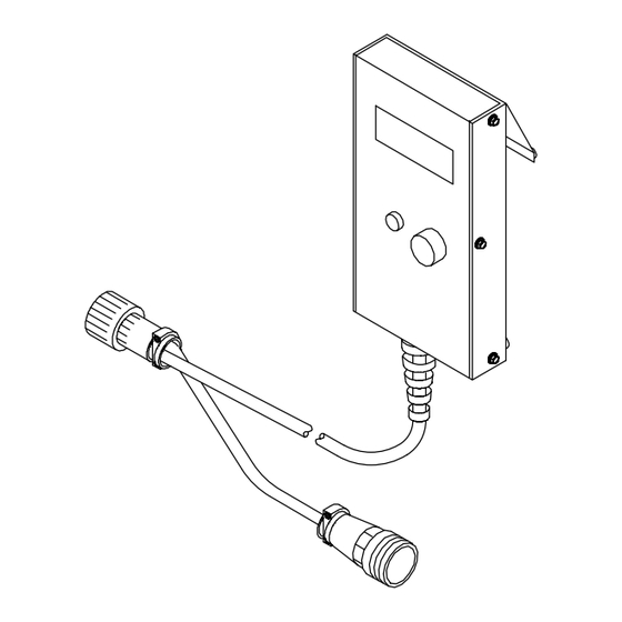
Power Sources Remote 14 Cord On Control Unit 14-Pin Extension Cord (Customer-Supplied) Use one of these MILLER exten- sion cords: 043 690 − 25 ft (7.6 m) 043 691 − 50 ft (15.2 m) Make sure total cord length does not exceed 200 ft (61 m). -
Page 16: Overview And Controls
3-3. Overview And Controls Overview The control unit provides three modes of operation: CV Mig − control functions as a re- mote voltage control. Manual MIG Pulser − control func- tions as a discrete pulsed MIG CC control. Synergic Pulser − programs that use factory-entered values are used to control process. -
Page 17: Initial Display, Manual Mig Pulser Mode, And Cv Mig Mode
3-4. Initial Display, Manual MIG Pulser Mode, And CV Mig Mode Software Number Defined Welding Power Source Type When power is applied, initial dis- play with software number and welding power source type appears momentarily, and then last program 304 model power source shown. to be viewed before control was shut down appears. -
Page 18: Setup Screens
3-5. Setup Screens To access Setup screens: turn welding power source Off, press and hold Select push button, turn unit On, and hold push button down until initial screen leaves. To exit Setup screens, turn welding power source Off and then On again. -
Page 19: Choosing Pulse Programs And Setting Parameters
3-6. Choosing Pulse Programs And Setting Parameters Choosing Pulse Program: Pulse programs are pre-written and cannot be changed by the user. See Sections 4 and 6 for program parameters. Choose program depending on the type and size of wire, and type of shielding gas used. For example, the program shown below is for .045 steel wire using 95Ar −... -
Page 20: How Manual Pulsed Mig Waveform Components Affect Arc And Burn-Off Rate
3-7. How Manual Pulsed MIG Waveform Components Affect Arc and Burn-off Rate Changes to Arc Comments A Electrode extension (stickout) B Arc length C Contact tube-to-work distance should be 3/8 in. to 3/4 in. Recommended gun angle is 10 to 20 de- grees from vertical. -
Page 21: Section 4 − Programs For 304 Model Welding Power Sources
SECTION 4 − PROGRAMS FOR 304 MODEL WELDING POWER SOURCES Section 4-1 provides basic information on each of the programs in the unit’s memory for the 304 Model welding power sources. See Section 4-2 for more detailed information on each of the programs. Synergic Information: The manufacturer makes no warranties, express or implied, that welds made using the synergic parameters of this equip- ment will meet the requirements of the application. - Page 22 Program 2 −− .047 Aluminum 5356 −− Argon (For 304 Models) Trim Peak Amp Background Amp Freq. Pulse Width Starting Amps 1.40 1.50 1.65 1.80 2.00 2.20 2.30 2.45 2.60 2.70 2.93 Program 3 −− .035 Aluminum 5356 −− Argon (For 304 Models) Trim Peak Amp Background Amp...
- Page 23 Program 5 −− .035 Aluminum 4043 −− Argon (For 304 Models) Trim Peak Amp Background Amp Freq. Pulse Width Starting Amps 1.20 1.25 1.30 1.40 1.56 1.74 1.90 2.14 2.23 2.54 2.80 Program 6 −− .045 ER70S−3 Mild Steel −− 98 Argon / 2 CO (For 304 Models) Trim Peak Amp...
- Page 24 Program 8 −− .035 ER70S−3 Mild Steel −− 98 Argon / 2 CO (For 304 Models) Trim Peak Amp Background Amp Freq. Pulse Width Starting Amps 1.60 1.66 1.80 1.99 2.15 2.25 2.35 2.45 2.60 2.70 2.85 Program 9 −− .035 ER70S−3 Mild Steel −− 95 Argon / 5 CO (For 304 Models) Trim Peak Amp...
- Page 25 Program 11 −− .045 309L Stainless Steel −− 95 Argon / 5 CO (For 304 Models) Trim Peak Amp Background Amp Freq. Pulse Width Starting Amps 1.80 2.00 2.00 2.20 2.40 2.50 2.50 2.65 2.70 2.80 2.80 Program 12 −− .035 309L Stainless Steel −− 98 Argon / 2 CO (For 304 Models) Trim Peak Amp...
- Page 26 Program 14 −− .035 Silicon Bronze −− Argon (For 304 Models) Trim Peak Amp Background Amp Freq. Pulse Width Starting Amps 1.20 1.30 1.43 1.51 1.50 1.70 1.82 1.88 1.96 2.10 2.16 Program 15 −− .052 Metal Core −− Recommended Gases: Argon/CO Gas: Argon/CO mixes up to 20% CO (For 304 Models)
-
Page 27: Section 5 − Programs For 350 Model Welding Power Sources
SECTION 5 − PROGRAMS FOR 350 MODEL WELDING POWER SOURCES Section 5-1 provides basic information on each of the programs in the unit’s memory for the 350 Model welding power sources. See Section 5-2 for more detailed information on each of the programs. Synergic Information: The manufacturer makes no warranties, express or implied, that welds made using the synergic parameters of this equip- ment will meet the requirements of the application. - Page 28 Program 2 −− .047 Aluminum 5356 −− Argon (For 350 Models) Trim Peak Amp Background Amp Freq. Pulse Width Starting Amps 1.40 1.50 1.65 1.80 2.00 2.20 2.30 2.45 2.60 2.70 2.93 Program 3 −− .035 Aluminum 5356 −− Argon (For 350 Models) Trim Peak Amp Background Amp...
- Page 29 Program 5 −− .035 Aluminum 4043 −− Argon (For 350 Models) Trim Peak Amp Background Amp Freq. Pulse Width Starting Amps 1.20 1.25 1.30 1.40 1.56 1.74 1.90 2.14 2.23 2.54 2.80 Program 6 −− .045 ER70S−3 Mild Steel −− 98 Argon / 2 CO (For 350 Models) Trim Peak Amp...
- Page 30 Program 8 −− .035 ER70S−3 Mild Steel −− 98 Argon / 2 CO (For 350 Models) Trim Peak Amp Background Amp Freq. Pulse Width Starting Amps 1.60 1.66 1.80 1.99 2.15 2.25 2.35 2.45 2.60 2.70 2.85 Program 9 −− .035 ER70S−3 Mild Steel −− 95 Argon / 5 CO (For 350 Models) Trim Peak Amp...
- Page 31 Program 11 −− .045 309L Stainless Steel −− 95 Argon / 5 CO (For 350 Models) Trim Peak Amp Background Amp Freq. Pulse Width Starting Amps 1.80 2.00 2.00 2.20 2.40 2.50 2.50 2.65 2.70 2.80 2.80 Program 12 −− .035 309L Stainless Steel −− 98 Argon / 2 CO (For 350 Models) Trim Peak Amp...
- Page 32 Program 14 −− .035 Silicon Bronze −− Argon (For 350 Models) Trim Peak Amp Background Amp Freq. Pulse Width Starting Amps 1.20 1.30 1.43 1.51 1.50 1.70 1.82 1.88 1.96 2.10 2.16 Program 15 −− .052 Metal Core −− Recommended Gases: Argon/CO Gas: Argon/CO mixes up to 20% CO (For 350 Models)
-
Page 33: Section 6 − Programs For 456 Model Welding Power Sources
SECTION 6 − PROGRAMS FOR 456 MODEL WELDING POWER SOURCES Section 6-1 provides basic information on each of the programs in the unit’s memory for the 456 Model welding power sources. See Section 6-2 for more detailed information on each of the programs. Synergic Information: The manufacturer makes no warranties, express or implied, that welds made using the synergic parameters of this equip- ment will meet the requirements of the application. -
Page 34: Programs For 456 Model Welding Power Sources
6-2. Programs For 456 Model Welding Power Sources Program 1 −− .035 Nickel −− 75 Argon / 25 Helium (For 456 Models) Trim Peak Amp Background Amp Freq. Pulse Width Starting Amps 2.85 2.96 3.08 3.20 3.32 3.40 3.48 3.55 3.62 3.69 3.76... - Page 35 Program 4 −− .047 Aluminum 5356 −− Argon (For 456 Models) Trim Peak Amp Background Amp Freq. Pulse Width Starting Amps 2.10 2.20 2.30 2.40 2.50 2.60 2.70 2.80 2.90 2.95 3.00 Program 5 −− .035 Aluminum 5356 −− Argon (For 456 Models) Trim Peak Amp Background Amp...
- Page 36 Program 7 −− .047 Aluminum 4043 −− Argon (For 456 Models) Trim Peak Amp Background Amp Freq. Pulse Width Starting Amps 2.00 2.16 2.42 2.55 2.68 2.81 2.92 3.02 3.12 3.26 3.38 Program 8 −− .035 Aluminum 4043 −− Argon (For 456 Models) Trim Peak Amp Background Amp...
- Page 37 Program 10 −− .052 ER70S−3 Mild Steel −− 95 Argon / 5 CO (For 456 Models) Trim Peak Amp Background Amp Freq. Pulse Width Starting Amps 2.30 2.43 2.58 2.70 2.80 2.90 3.00 3.10 3.15 3.18 3.20 Program 11 −− .045 ER70S−3 Mild Steel −− 95 Argon / 5 CO (For 456 Models) Trim Peak Amp...
- Page 38 Program 13 −− .045 309L Stainless Steel −− 98 Argon / 2 CO (For 456 Models) Trim Peak Amp Background Amp Freq. Pulse Width Starting Amps 1.50 1.65 1.75 1.85 1.97 2.09 2.20 2.30 2.40 2.50 2.60 Program 14 −− .035 309L Stainless Steel −− 98 Argon / 2 CO (For 456 Models) Trim Peak Amp...
- Page 39 Program 16 −− .062 Metal Core −− Recommended Gases: Argon/CO Gases: Argon/CO mixes up to 20% CO (For 456 Models) Trim Peak Amp Background Amp Freq. Pulse Width Starting Amps 2.10 2.30 2.40 2.50 2.60 2.75 2.90 3.05 3.20 3.35 3.50 Program 17 −−...
-
Page 40: Section 7 − Troubleshooting
SECTION 7 − TROUBLESHOOTING 7-1. Error Codes Program CRC Error Program Range Error If either error code appears, reset the display to factory settings as fol- lows: Press Parameter Select push but- ton or turn welding power source Off and back On. Change settings and continue. -
Page 41: Section 8 − Electrical Diagram
SECTION 8 − ELECTRICAL DIAGRAM Figure 8-1. Circuit Diagram 182 109-C OM-2805 Page 37... -
Page 42: Section 9 − Parts List
SECTION 9 − PARTS LIST Item Dia. Part Mkgs. Description Quantity Figure 9-1. Main Assembly ... . . 174 960 Panel, Rear & Sides .......... - Page 43 Effective January 1, 2014 (Equipment with a serial number preface of ME or newer) This limited warranty supersedes all previous Miller warranties and is exclusive with no other guarantees or warranties expressed or implied. Warranty Questions? LIMITED WARRANTY − Subject to the terms and conditions below, 6 Months —...
-
Page 44: For Service
Contact the Delivering Carrier to: File a claim for loss or damage during shipment. For assistance in filing or settling claims, contact your distributor and/or equipment manufacturer’s Transportation Department. © ORIGINAL INSTRUCTIONS − PRINTED IN USA 2014 Miller Electric Mfg. Co. 2014−01...