Publicité
Liens rapides
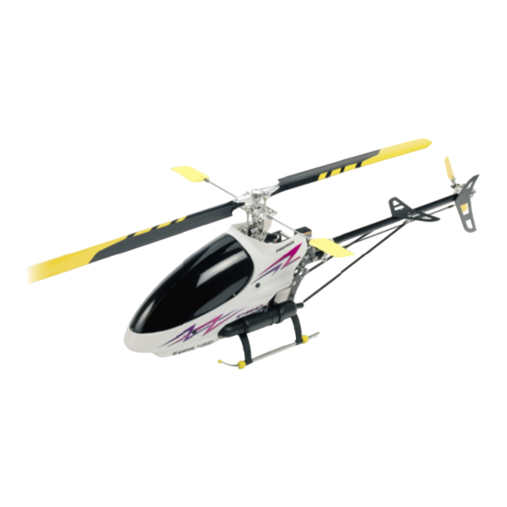
ZOOM
ZOOM
450
450
Instruction manual • Bouwhandleiding • Bauanleitung • Instructions de montage
WARNING !
This R/C kit and the model you
will build is not a toy.
Only for experienced modellers.
version: 26/07/07
IC powered micro helicopter
WWW.PROTECH.be
LET OP !
Deze bouwdoos van een
radiobestuurd model is geen
speelgoed.
Enkel voor ervaren modelbouwers.
IC
IC
PRO
PRO
ACHTUNG !
Dieser Bausatz eines
ferngesteuerten Modells
ist kein Spielzeug.
Nur für erfahrene Modellbauer.
T0522
ATTENTION !
Ce modèle n'est pas un jouet.
Seulement pour modélistes
expérimentés.
Publicité

Manuels Connexes pour protech ZOOM 450 IC PRO


Sommaire des Matières pour protech ZOOM 450 IC PRO
- Page 1 ZOOM ZOOM T0522 IC powered micro helicopter Instruction manual • Bouwhandleiding • Bauanleitung • Instructions de montage WWW.PROTECH.be WARNING ! LET OP ! ACHTUNG ! ATTENTION ! This R/C kit and the model you Deze bouwdoos van een Dieser Bausatz eines Ce modèle n’est pas un jouet.
- Page 2 Specifi cations / Specifi caties / Technische Daten / Spécifi cations Rotor Ø: 770-810 mm Rotor Ø: 770-810 mm Rotor Ø: 770-810 mm Rotor Ø: 770-810 mm Vlieg gewicht: 900 g Flying weight: 900 g Fluggewicht: 900 g Poids en vol: 900g Radiobesturing: 6 kanaals Radio required: 6 ch radio...
- Page 3 Step / Stap / Etape / Schritt T0502.026 Nut set M3, 10 pcs T0502.055 Tail rotor input gear set T0502.079 Ball bearing 3x8x3 mm T0502.021 Belt transmission shaft T0502.053 Tail bearing mount T0503.023 Tail transmission gear T0502.079 Ball bearing 3x8x3 mm •...
- Page 4 Step / Stap / Etape / Schritt Use Nut Lock on all screws ! Appliquer du Nut Lock sur toutes les vis ! #A600 Don’t tighten yet ! Gebruik Nut Lock op alle schroeven ! Nut Lock Ne pas serrer maintenant ! Alle Schrauben mit Schraubensicherung sichern ! Nog niet vastdraaien Nicht fest ziehen...
- Page 5 Step / Stap / Etape / Schritt T0503.030 Canopy mount set #A600 Nut Lock REPEAT L & R T0503.200 Main frame Use Nut Lock on all screws ! Appliquer du Nut Lock sur toutes les vis ! Gebruik Nut Lock op alle schroeven ! #A600 Nut Lock Alle Schrauben mit Schraubensicherung sichern !
- Page 6 Step / Stap / Etape / Schritt T0502.023 Screw for main frame set M2x7mm, 10pcs #A600 Nut Lock Use a small amount of instant glue on these screws. Doe een klein beetje secondenlijm op deze schroefjes. Utiliser un peu de la colle cyano pour l’assemblage. Benutzen Sie Sekundenkleber für die Montage.
- Page 7 Step / Stap / Etape / Schritt Oil lightly ! Huiler légèrement ! Lichtjes inoliën Leicht Ölen T0502.015 Auto rotation sleeve set T0503.022 Main gear set T0502.078 Ball bearing 2x5x2,5 T0502.214 Washout base arm set T0502.213 Washout base Expert T0502.013 Brass ball with screw Beginner Use a small amount of locktite on these screws.
- Page 8 Step / Stap / Etape / Schritt #A600 Nut Lock T0502.216 Swashplate assembly T0502.006 Main shaft MA2010 M2 nut MA2025 M2x15mm screw Assemble and adjust the control rods to the lengths shown Assembler les commandes aux longueurs indiquées Maak de controle links zoals afgebeeld Montieren Sie die Gestänge wie abgebildet 43,5 mm 27,5 mm...
- Page 9 Step / Stap / Etape / Schritt T0502.002 Aluminium main rotor shaft set #A600 Nut Lock T0502.003 Aluminium main T0502.072 rotor head set Ball bearing 3x6x2mm T0502.078 Ball bearing 2x5x2,5mm T0502.212 see-saw set T0502.005 Aluminium see-saw set T0502.075 Ball bearing 3x8x4mm T0502.043 Flybar see-saw holder MA2011...
- Page 10 Step / Stap / Etape / Schritt Parallel #A600 Nut Lock Parallel 10 •...
- Page 11 Step / Stap / Etape / Schritt T0502.074 T0502.220 Ball bearing 5x8x2,5 mm Tail pitch control lever set Do not overtighten! Ne pas serrer trop fort! Niet te vast aandraaien! Nicht zu fest anziehen! T0502.076 T0502.221 Ball bearing 3x6x2,5 mm Tail pitch yoke set T0502.084 Tail pitch bushing...
- Page 12 Step / Stap / Etape / Schritt T0520.215 Tail servo mount set T0502.029 90° Aluminium tail boom T0503,202 Stabilizer/Fin set T0502.238 Tailboom support set Use locktite to assemble the tail rod. Gebruik locktite voor de montage. Utiliser locktite pour assembler. Benützen Sie Locktite zum montieren.
- Page 13 Step / Stap / Etape / Schritt Installing the tail boom. Installation du tube de queue. Installeren van de staartbuis. Heckauslegermontage. Use a small amount of instant glue on these screws. Doe een klein beetje secondenlijm op deze schroefjes. Utiliser un peu de colle cyano pour l’assemblage. Benutzen Sie Sekundenkleber für die Montage.
- Page 14 Step / Stap / Etape / Schritt Installing the tail servo. Installation du servo pour la commande de l’anticouple. Installatie van de staartrotorservo. Montieren des Heckrotorservos. 10,5mm Neutral position 90° Tail rod assembly. Assemblage de la commande de l’anticouple. Montage van de staartrotoraansturing. Montieren der Heckrotoranlenkung.
- Page 15 Step / Stap / Etape / Schritt Move the servoholder on the boom to obtain the correct 90° angle of the tail rotor. Bouger le servo sur le tube de queue pour obtenir les 90°. Verplaats de servohouder op de staartbuis om de juiste hoek (90°) van de staartrotor te bekomen. Bewegen Sie der Servohalter um die Heckrotoranlenkung auf 90°...
- Page 16 Step / Stap / Etape / Schritt T0503.210 Engine cooling fan CNC #A600 T0503.014 Nut Lock Hex start adapter T0503.028 Ball bearing 9,5x6,3x3,17mm T0503.011 Clutch liner T0503.009 Engine gear T0503.028 T0503.010 Ball bearing Metal clutch 9,5x6,3x3,17mm T0503.008 Screw set for engine M3x8mm, 10pcs T0503.030 Engine mount...
- Page 17 Step / Stap / Etape / Schritt #A600 Nut Lock The gearmesh should be adjusted correctly. If the distance between the gears is incorrect, the gears will wear out quickly. There must be a tiny amount of play between the gears. Adjust this by moving the motormount Le jeu entre le pignon et la couronne doit être le plus correct possible autrement vous provoquerez une usure prématurée de la couronne.
- Page 18 Step / Stap / Etape / Schritt Installing the servos Installation des servos Montage van de servo’s Servoeinbau 39mm 37mm 35,5mm 12,5mm Neutral position 90° Receiver switch (sold separately Parallel neutral position Neutral position 0° 18 •...
- Page 19 Step / Stap / Etape / Schritt Installing the servos Installation des servos Montage van de servo’s Servoeinbau 30mm 30mm 25mm 12,5mm Neutral position 90° Neutral position 180° • 19...
- Page 20 Step / Stap / Etape / Schritt T0502.201 Main rotor blades PRO.303 Micro heading lock gyro T0502.027 M3x12 mm Installing the gyro with double side foam Installer le gyro avec de la mousse adhésive double face Monteer de gyroscoop met dubbelzijdige kleef- band Montieren Sie den Kreisel mit doppelseitigem Klebeband...
- Page 21 Step / Stap / Etape / Schritt Assemble the canopy as shown. Assemblez la cabine comme dans le dessin. Assembller de cockpit zoals afgebeeld. Montieren Sie die Kabinehaube wie abgebildet. • 21...
- Page 22 ADJUSTMENTS ADJUSTMENTS BLADE TRACKING ADJUSTMENT (to avoid vibrations) ALIGNEMENT DES PALES (pour éviter les vibrations) BLADSPOOR REGELEN ( om trillingen te vermijden) BLATTSPURLAUF EINSTELLEN (Vibrationen beseitigen) FALSE TAPE Shorten the rod connected to the blade that is too high one revolution at a time until both blades turn in the same plane.
- Page 23 ADJUSTMENTS ADJUSTMENTS CENTRE OF GRAVITY CENTRE DE GRAVITE ZWAARTEPUNT SCHWERPUNKT Adjust the centre of gravity by moving the RX battery. Ajustez le centre de gravité en déplaçant l’accu du récepteur. Pas het zwaartepunt aan door de ontvangerbatterij te verschuiven. Bewegen Sie den Empfängerakku um den Schwerpunkt zu justieren. •...
- Page 24 TRANSMITTER ADJUSTMENTS JR/GRAUPNER TRANSMITTER ADJUSTMENTS JR/GRAUPNER New Helicopter model Swashtype: 3 servos 120° Swashmix AIL -50% ELE 50% PITCH 45% CH4-5 TO GYRO 24 •...
- Page 25 TRANSMITTER ADJUSTMENTS FUTABA/HITEC TRANSMITTER ADJUSTMENTS FUTABA/HITEC New Helicopter model Swashtype: SR3 Swashmix AIL 50% ELE 50% PITCH 45% CH4-5 TO GYRO • 25...
- Page 26 MODE 1 MODE 1 TRANSMITTER OPERATION AND CONTROL • Elevator • Nick • Tangage • Nick STICK INPUT SERVO ACTION HELI ACTION Elevator • Nick • Tangage • Nick STICK INPUT SERVO ACTION HELI ACTION Tail • Staart • Anticouple • Heck STICK INPUT SERVO ACTION HELI ACTION...
- Page 27 MODE 1 MODE 1 TRANSMITTER OPERATION AND CONTROL • Pitch • Pitch • Pitch • Pitch STICK INPUT SERVO ACTION HELI ACTION Pitch • Pitch • Pitch • Pitch STICK INPUT SERVO ACTION HELI ACTION Roll • Rol • Roll • Roulis STICK INPUT SERVO ACTION HELI ACTION...
- Page 28 MODE 1 MODE 1 TRIM ADJUSTMENT • If the helicopter does not fl y in neutral position, adjust the TRIM. The TRIM adjustment depends on the helicopter action. Als de helicopter niet in de neutrale positie vliegt, moet men de “TRIM“ aanpassen. Het aanpassen van de “TRIM“ hangt af van wat de helicopter doet op dat moment.
- Page 29 MODE 2 MODE 2 TRANSMITTER OPERATION AND CONTROL • Pitch • Pitch • Pitch • Pitch STICK INPUT SERVO ACTION HELI ACTION Pitch • Pitch • Pitch • Pitch STICK INPUT SERVO ACTION HELI ACTION Roll • Rol • Roll • Roulis STICK INPUT SERVO ACTION HELI ACTION...
- Page 30 MODE 2 MODE 2 TRANSMITTER OPERATION AND CONTROL • Elevator • Nick • Tangage • Nick STICK INPUT SERVO ACTION HELI ACTION Elevator • Nick • Tangage • Nick STICK INPUT SERVO ACTION HELI ACTION Tail • Staart • Anticouple • Heck STICK INPUT SERVO ACTION HELI ACTION...
- Page 31 MODE 2 MODE 2 TRIM ADJUSTMENT • If the helicopter does not fl y in neutral position, adjust the TRIM. The TRIM adjustment depends on the helicopter action. Als de helicopter niet in de neutrale positie vliegt, moet men de “TRIM“ aanpassen. Het aanpassen van de “TRIM“ hangt af van wat de helicopter doet op dat moment.
- Page 32 3D SETUP 3D SETUP 3D Setup Réglage pour vol 3D 3D afstelling 3D Einstellung -10° Stick low position 0° Stick neutral position +10° Stick high position 32 •...
- Page 33 3D SETUP 3D SETUP Use these settings as a guide to set up your radio. Utilisez ces réglages comme base pour programmer votre emetteur. Gebruik deze afstellingen als basis om de zender te programmeren. Benutzen Sie diese Einstellungen als Beispiel um Ihre RC-Anlage zu programmieren. PITCH Use a linear pitch curve 0-100% for all conditions.
- Page 34 STANDARD SETTING STANDARD SETTING Standard Setting Réglage standard Standaard afstelling -3° Standard Einstellung Stick low position 5° Stick neutral position 10° Stick high position 34 •...
- Page 35 STANDARD SETTING STANDARD SETTING Use these settings as a guide to set up your radio. Utilisez ces réglages comme base pour programmer votre emetteur. Gebruik deze afstellingen als basis om de zender te programmeren. Benutzen Sie diese Einstellungen als Beispiel um Ihre RC-Anlage zu programmieren. PITCH Use a linear pitch curve 0-100% for all conditions.
- Page 36 SPARE PARTS SPARE PARTS T0502.001 Aluminium main rotor yoke set T0502.002 Aluminium main rotor shaft set T0502.003 Aluminium main rotor head set T0502.004 Aluminium rotor fi xing set T0502.005 Aluminium see-saw set T0502.006 Main shaft T0502.007 Main shaft stopper set T0502.008 Stabilizer T0502.010...
- Page 37 SPARE PARTS SPARE PARTS T0502.043 Fly bar see-saw holder T0502.050 Canopy mount set T0502.053 Tail bearing mount T0502.052 Landing gear braces T0502.054 Tail boom mount set T0502.055 Tail rotor input gear set T0502.056 Tail drive gear assembly T0502.063 Belt set T0502.067 O-ring set T0502.068...
- Page 38 SPARE PARTS SPARE PARTS T0502.211 Precision Flybar control system T0502.212 Aluminium see-saw set T0502.213 Aluminium washout base set T0502.214 Aluminium washout arms set T0502.215 Aluminium L arms set T0502.216 Aluminium swashplate set T0502.219 Aluminium tailcase set T0502.220 Aluminium tail pitch lever T0502.221 Aluminium tail pitch yoke T0502.223...
- Page 39 SPARE PARTS SPARE PARTS T0503.010 Metal clutch T0503.011 Clutch liner T0503.012 Muffl er gasket set, 10pcs T0503.013 Tune pipe with joint set T0503.014 Hex start adapter T0503.017 Receiver mount T0503.020 Canopy window T0503.021 Canopy set T0503.022 T0503.023 Tail transmission gear set T0503.024 Fuel tank set T0503.026...
- Page 40 OPTION PARTS OPTION PARTS T0520.215 tail servo mount set O P T I O N O P T I O N PA R T S PA R T S T0502.208 Dual o-ring headblock T0502.201 Carbon tailboom T0520.210 Carbon stabilizer set 40 •...
- Page 41 SPARE PARTS SPARE PARTS Glow plug P10003 M1040.013 Cylinder head screws M1040.012 Cylinder head gasket M1040.080 Cylinder head M1040.010 Cylinder/piston M1040.009 Piston pin M1040.011 Burn room M1040.030 Piston pin clips M1040.008 Connecting rod M1040.081 M1040.015 Cranck case Cranckcase cover screws M1040.022 Rear ball bearing M1040.088...
- Page 42 SAFETY INSTRUCTIONS SAFETY INSTRUCTIONS SAFETY INSTRUCTIONS _____________________________________________________________________________ Please remember that this model engine is not a toy. If not used correctly, it can cause physical harm to you and others. As owner and operator, you are responsible for the safe operation of this engine, so do not disregard safety instructions. •...
- Page 43 SAFETY INSTRUCTIONS SAFETY INSTRUCTIONS VEILIGHEIDSVOORSCHRIFTEN ______________________________________________________________________ Deze model motor is geen speelgoed. Bij verkeerd gebruik kan deze fysiek letsel veroorzaken bij u en omstaanders. Als eigenaar en gebruiker, bent u verantwoordelijk voor het gebruik van deze motor. Lees de veiligheidsvoorschriften en pas deze toe. •...
- Page 44 MATERIAL MATERIAL MATERIAL __________________________________________________________________________________________ GLOW PLUG • SX-12 engines work with any MEDIUM quality glowplug. • Always use a glowplug washer. • Use of fuel with a moderate percentage of nitro will prolong the life of your glowplug. • Don’t leave the glowdriver, glowshot or battery connected to the glowplug longer than necessary. •...
- Page 45 STARTING EQUIPMENT STARTING EQUIPMENT STARTING EQUIPMENT _____________________________________________________________________________ You will need following items to start your engine: - Fuel: Use a quality brand fuel containing at least 10% nitromethane. - Glowplug and plug wrench: Install a medium glowplug in the cylinderhead using an 8 mm socket wrench. Don’t forget the glowplug washer. Do not overtighten the plug as this may damage the thread in the cylinderhead.
- Page 46 STARTING PROCEDURE STARTING PROCEDURE Throttle stop screw Vis de blocage Stop schroef Gasbegrenzerschraube High speed needle Pointeau principal Hoofdnaald Nadelventil Throttle drum 1/4 open Tambour ouvert 1/4 Gasschuif 1/4 open Gasschieber 1/4 geöffnet Throttle lever Levier de commande Gas arm Gasschieber Throttle drum Tambour...
- Page 47 STARTING PROCEDURE STARTING PROCEDURE START PROCEDURE ___________________________________________________________________ - Maak het model vast zodat het niet kan bewegen. - Vul de tank met de gasschuif gesloten. Stop tijdig, anders zal de brandstof in de uitlaat lopen. - De afstelling van de naalden is tijdens de assemblage reeds geregeld: schroef de hoofdnaald volledig in (NIET VASTDRAAIEN) en schroef ze 2 omwenteling uit (tegenwijzerzin).
- Page 48 NEEDLE SETTINGS NEEDLE SETTINGS Standard setting Réglage de base Open (richer) Ouvrir (+riche) Close (leaner) Fermer (+pauvre) Close (leaner) Fermer (+pauvre) Open (richer) Ouvrir (+riche) NEEDLE SETTINGS ____________________________________________________________________ Carburettor principal: The carburettor consists of 2 major parts - The air intake (which is adjusted by turning the throttle drum) controls the engine speed. - The fuel mixture valve (which is adjusted by the 2 needles) controls the fuel/air mixture.
- Page 49 NEEDLE SETTINGS NEEDLE SETTINGS Standaard setting Standard Einstellung Open (rijker) Ausschrauben (Fetter) Dicht (armer) Einschrauben (Mager) Dicht (armer) Einschrauben (Mager) Open (rijker) Ausschrauben (Fetter) AFSTELLING VAN DE NAALDEN ________________________________________________________ Carburator principe: De carburator bestaat uit 2 delen - De luchtinlaat (die wordt geregeld door de gasschuif) controleert de motorsnelheid. - de brandstof verstuiver (die wordt geregeld door de hoofd- en stationairnaald) controleert het brandstof/luchtmengsel.
- Page 50 TROUBLESHOOTING TROUBLESHOOTING AFTER RUNNING THE ENGINE __________________________________________________________ Before you store the model, disconnect the fuel supply and try to start the engine. If it doesn’t fi re anymore, spray some AFTER RUN OIL in the carburettor (air intake) and turn the engine over a couple of seconds. This will prevent the engine internal from corroding during storage.
- Page 51 TROUBLESHOOTING TROUBLESHOOTING NA GEBRUIK ___________________________________________________________________________ Voordat het model wordt opgeborgen, wordt de motor best leeggemaakt. Ontkoppel de brandstofl eiding en probeer de motor te starten. Indien hij niet meer start, laat enkele druppels after run olie in de luchtinlaat vallen en laat de motor enkele seconden draaien met de elektrische starter om de olie te verspreiden.
- Page 52 Flying area / Vliegomgeving / Flugplatz / Terrain de vol CAUTION OPGEPAST ACHTUNG ATTENTION Do not fl y helicopter near : Nooit vliegen in de nabijheid van: Niemals in der nehe von: Ne jamais voler à proximité de: • People or animals •...
- Page 53 Flight lesson / Vlieglessen / Die Flugstunden / 1er vol Place the model with the front in Plaats het model met de neus in Setzen Sie das Modell mit der Placez le modèle nez au vent the wind and stand behind the de wind en ga achter het model Näse voran gegen den Wind et installez-vous derrière le...
- Page 54 NOTES 54 •...
- Page 55 NOTES • 55...
- Page 56 Visit our website www.protech.be PROTECH® is a registered trademark Geelseweg 80 • B-2250 OLEN • Belgium Tel. +32 (0)14-25 92 83 • E-mail: info@protech.be www.protech.be...