CAME BX704AGS Manuel D'installation
Masquer les pouces
Voir aussi pour BX704AGS:
- Manuel d'installation (29 pages) ,
- Manuel d'installation (33 pages) ,
- Manuel d'installation (32 pages)

Manuels Connexes pour CAME BX704AGS


Sommaire des Matières pour CAME BX704AGS
- Page 1 FA01775M04 Automazioni per cancelli scorrevoli BX704AGS BX708AGS BX708RGS BX704ALS BX708ALS Italiano MANUALE DI INSTALLAZIONE English Français Русский...
- Page 3 AVVERTENZE GENERALI PER L'INSTALLATORE Importanti istruzioni di sicurezza. Seguire tutte le istruzioni, in quanto un'installazione non corretta può portare a lesioni gravi. Prima di procedere, leggere anche le avvertenze generali per l'utilizzatore. Il prodotto deve essere destinato solo all’uso per il quale è stato espressamente studiato e ogni altro uso è da considerarsi pericoloso.
- Page 4 CAME S.p.A. implementa all’interno dei propri stabilimenti un Sistema di Gestione Ambientale certificato e conforme alla norma UNI EN ISO 14001 a garanzia del rispetto e della tutela dell’ambiente. Vi chiediamo di continuare l’opera di tutela dell’ambiente, che CAME considera uno dei fondamenti di sviluppo delle proprie strategie operative e di mercato, semplicemente osservando brevi indicazioni in materia di smaltimento: SMALTIMENTO DELL’IMBALLO...
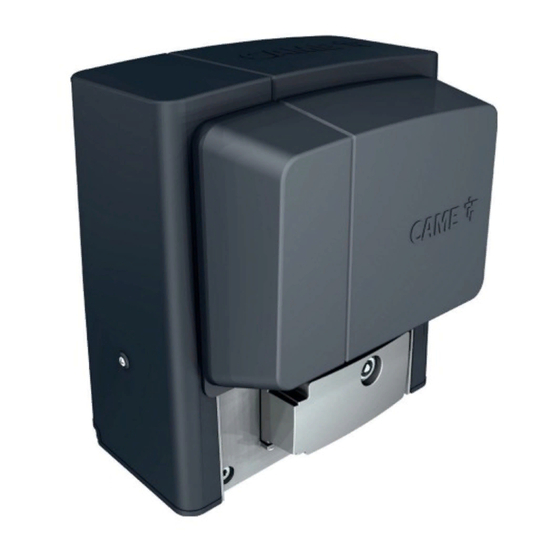
- Page 5 801MS-0020 BX704AGS - Automazione con motore a 230 V, completa di scheda elettronica con display di programmazione, decodifica radio incorporata, gestione del movimento e rilevazione degli ostacoli con finecorsa meccanici per cancelli scorrevoli fino a 400 kg e 14 m di lunghezza. Cover grigio RAL7024.
- Page 6 Descrizione delle parti Automazione Coperchio Scheda elettronica Coperchio frontale Alette di finecorsa Motoriduttore Trasformatore Condensatore Sportello di sblocco Finecorsa meccanico Minuteria di fissaggio Piastra di fissaggio Staffe di montaggio per alloggiamento accessori (opzionale) Supporto per scheda elettronica...
- Page 7 Scheda elettronica Le funzioni sui contatti di ingresso e di uscita le regolazioni dei tempi e la gestione degli utenti sono impostate e visualizzate sul display. Tutte le connessioni sono protette da fusibili rapidi. Per un funzionamento corretto, prima di inserire una qualsiasi scheda a innesto, è OBBLIGATORIO TOGLIERE LA TENSIONE DI LINEA e, se presenti, scollegare le batterie.
- Page 8 Dimensioni Limiti di impiego MODELLI BX704AGS BX708AGS BX704ALS BX708ALS BX708RGS Modulo del pignone Lunghezza massima anta (m) Peso massimo anta (kg) Dati tecnici MODELLI BX704AGS BX708AGS BX704ALS BX708ALS BX708RGS Alimentazione (V - 50/60 Hz) 230 AC 230 AC 230 AC...
- Page 9 Il calcolo dei cicli di lavoro si riferisce a un cancello con lunghezza standard di riferimento della parte scorrevole, installato a regola d’arte, privo di conflitti meccanici e/o attriti accidentali, misurati a temperatura ambiente di 20° C, come definito dalla Norma EN 60335-2-103. MODELLI BX704AGS BX708AGS BX704ALS...
- Page 10 Tipi di cavi e spessori minimi Lunghezza del cavo (m) fino a 20 da 20 a 30 Alimentazione 230 V AC 3G x 1,5 mm2 3G x 2,5 mm2 Lampeggiatore 230 V AC 2 x 1,5 mm2 2 x 1,5 mm2 Fotocellule TX 2 x 0,5 mm2 2 x 0,5 mm2...
- Page 11 INSTALLAZIONE Le seguenti illustrazioni sono solo esempi in quanto lo spazio per il fissaggio dell’automazione e degli accessori varia a seconda della zona di installazione. Spetta all’installatore scegliere la soluzione più adatta. I disegni si riferiscono all’automazione installata a sinistra. Operazioni preliminari Fare lo scavo per la cassa matta.
- Page 12 Inserire le viti fornite nella piastra di fissaggio. Bloccare le viti con i dadi forniti. Estrarre le zanche preformate, utilizzando un cacciavite. Inserire la piastra di fissaggio nella griglia di ferro. I tubi devono passare attraverso i fori predisposti. UNI 5739 12 X 70 Posizionare la piastra di fissaggio rispettando le misure riportate sul disegno.
- Page 13 Togliere i dadi dalle viti. Inserire i cavi elettrici nei tubi fino a farli uscire di 600 mm circa. Preparazione dell'automazione Rimuovere il coperchio frontale. Rimuovere il coperchio dell'automazione.
- Page 14 Posizionare l'automazione sopra la piastra di fissaggio. I cavi elettrici devono passare sotto la cassa dell'automazione Sollevare l'automazione di 5÷10 mm dalla piastra agendo sui piedini filettati per permettere eventuali regolazioni successive tra pignone e cremagliera. Fissaggio della cremagliera Sbloccare l'automazione. Appoggiare la cremagliera sul pignone.
- Page 15 Regolazione accoppiamento pignone-cremagliera Aprire e chiudere il cancello manualmente. Registrare la distanza dell'accoppiamento pignone-cremagliera con i piedini filettati (regolazione verticale) e le asole (regolazione orizzontale). Il peso del cancello non deve gravare sull'automazione. Fissaggio dell'automazione Procedere al fissaggio solo dopo aver regolato l'accoppiamento pignone-cremagliera. Fissare l'automazione alla piastra di fissaggio con gli scontri e i dadi.
- Page 16 Determinazione dei punti di finecorsa con finecorsa meccanici Aprire il cancello. Infilare l'aletta di finecorsa di apertura sulla cremagliera. La molla deve far scattare il micro. Fissare l'aletta di finecorsa di apertura con le viti senza testa (fornite). ~ 20 mm Chiudere il cancello.
- Page 17 COLLEGAMENTI ELETTRICI Passaggio dei cavi elettrici Eseguire i collegamenti elettrici secondo le disposizioni vigenti. I cavi elettrici non devono entrare in contatto con parti che possono riscaldarsi durante l'uso (per esempio: motore e trasformatore). Utilizzare dei pressacavi per collegare i dispositivi al quadro comando. Uno di questi deve essere destinato esclusivamente per il cavo di alimentazione. Passacavi del supporto scheda Alimentazione Durante tutte le fasi dell’installazione assicurarsi di operare fuori tensione.
- Page 18 Uscita alimentazione per accessori L'uscita eroga normalmente 24 V AC. La somma degli assorbimenti degli accessori connessi non deve superare i 20 W. Limitatore di coppia Cavo bianco Cavo nero Cavo rosso Cavo blu Cavo viola Cavo arancione Per variare la coppia motore, spostare il faston indicato su una delle 4 posizioni;...
- Page 19 Dispositivi di comando Selettore a tastiera Lettore per tessere Selettore transponder Pulsante di STOP (contatto NC) Arresta il cancello ed esclude l’eventuale chiusura automatica. Usare un dispositivo di comando per riprendere il movimento. Se il contatto non viene utilizzato, deve essere disattivato in fase di programmazione. Dispositivo di comando (contatto NO) Funzione APERTURA PARZIALE Dispositivo di comando (contatto NO)
- Page 20 Fotocellule DIR / DELTA-S Fotocellule DIR / DELTA-S Collegamento standard Collegamento con test di sicurezza Vedi funzione [F5] test sicurezze. 2 TX C NC TX 2 2 TX C NC TX 2 Bordo sensibile DFWN C NO NC DFWN...
- Page 21 PROGRAMMAZIONE Funzione dei tasti di programmazione Tasto ESC Il tasto ESC permette di eseguire le operazioni di seguito descritte. Uscire dal menu Annullare le modifiche Tornare alla schermata precedente Arrestare l'automazione Tasti < > I tasti < > permettono di eseguire le operazioni di seguito descritte. Navigare attraverso le voci del menu Incrementare o decrementare un valore Chiudere o aprire l'automazione...
- Page 22 Test sicurezze Attiva il controllo del corretto funzionamento delle fotocellule collegate agli ingressi selezionati, dopo ogni comando di apertura e chiusura. Eseguire il test collegando le fotocellule al morsetto TS [vedi paragrafo Dispositivi di sicurezza]. OFF (Default) 1 = CX 2 = CY 4 = CX+CY Azione mantenuta...
- Page 23 Lampada supplementare Permette di scegliere la modalità di funzionamento del dispositivo di illuminazione collegato all'uscita E1. 0 = Lampeggiatore (Default) 1 = Lampada ciclo - La lampada rimane accesa per tutta la manovra. La lampada rimane spenta se non viene impostato un tempo di chiusura automatica. Questo parametro non appare nel caso in cui la funzione [F19 - Chiusura automatica] sia disattivata.
- Page 24 Sensibilità rallentamento Regola, in percentuale, la sensibilità di rilevazione degli ostacoli durante la fase di rallentamento. Questa funzione compare solo se è attiva la funzione [F11 - Encoder]. da 10% a 100% (Default 100%) 10% = minima spinta e elevata sensibilità all'ostacolo 100 % =massima spinta e bassa sensibilità...
- Page 25 Passaggio parametri MASTER-SLAVE Condivide i parametri programmati sul cancello Master con il cancello Slave. Questa funzione compare solo se è attiva la funzione [F49 - RSE]. OFF (Default) Direzione apertura Imposta la direzione di apertura del cancello. 0 = Verso sinistra (Default) 1 = Verso destra Indirizzo CRP Assegna un codice identificativo univoco (indirizzo CRP) alla scheda elettronica.
- Page 26 Nuovo utente Permette di registrare un massimo di 250 utenti e di assegnare ad ognuno di essi una funzione. L’operazione può essere svolta mediante un trasmettitore o altro dispositivo di comando. Le schede che gestiscono i dispositivi di comando (AF - R700 - R800) devono essere innestate nei connettori.
- Page 27 Reset parametri Ripristina le impostazioni di fabbrica ad esclusione delle funzioni: [Decodifica radio], [Tipo motore] e le impostazioni relative alla taratura della corsa. OFF (Default) ON (Esegue l'operazione) Conteggi manovre Permette di visualizzare il numero di manovre effettuate dall'automazione. 001 = 100 manovre 010 = 1000 manovre 100 = 10000 manovre 999 = 99900 manovre...
- Page 28 MESSAGGI DI ERRORE Errore di calibrazione Errore di taratura Errore rottura encoder Errore di test servizi fallito Errore tempo di lavoro Errore sportello sblocco aperto Verificare che il fusibile accessori non sia bruciato. Ostacolo rilevato durante la chiusura Ostacolo rilevato durante l'apertura Superato il numero massimo di ostacoli rilevati consecutivamente Errore comunicazione Errore trasmettitore non compatibile...
- Page 29 FUNZIONAMENTO ABBINATO Comando unico di due automazioni collegate. Collegamenti elettrici Collegare le due schede elettroniche con un cavo tipo UTP CAT 5. Inserire una scheda RSE su entrambe le schede elettroniche. Procedere con il collegamento elettrico dei dispositivi e degli accessori. I dispositivi e gli accessori vanno collegati sulla scheda elettronica che verrà...
- Page 30 MCBF Modelli BX704 BX708 14 m - 400 kg 150000 14 m - 800 kg 150000 Installazione in zona ventosa -15% -15% Le percentuali indicano di quanto si debba ridurre il numero di cicli in relazione al tipo e numero di accessori installati. Prima di effettuare qualunque operazione di pulizia, manutenzione o sostituzione di parti, togliere l’alimentazione al dispositivo.
- Page 32 INCOLLARE QUI L'ETICHETTA DI PRODOTTO PRESENTE SULLA CONFEZIONE CAME S.p.A. Via Martiri della Libertà, 15 31030 Dosson di Casier Treviso - Italy Tel. (+39) 0422 4940 Fax (+39) 0422 4941...
- Page 33 FA01775-EN Sliding-gate operators BX704AGS BX708AGS BX708RGS BX704ALS BX708ALS INSTALLATION MANUAL English...
- Page 35 GENERAL PRECAUTIONS FOR INSTALLERS Important safety instructions. Please follow all of these instructions. Improper installation may cause serious bodily harm. Before continuing, please also read the general precautions for users. Only use this product for its intended purpose. Any other use is hazardous. • The manufacturer cannot be held liable for any damage caused by improper, unreasonable or erroneous use.
- Page 36 DISMANTLING AND DISPOSAL CAME S.p.A. employs an Environmental Management System at its premises. This system is certified and compliant with the UNI EN ISO 14001 standard to ensure that the environment is respected and safeguarded. Please continue safeguarding the environment. At CAME we consider it one of the fundamentals of our operating and market strategies.
- Page 37 801MS-0020 BX704AGS - Operator with 230 V motor, featuring a control board with programming display, on-board radio decoding, movement and obstruction detecting device with mechanical limit switch for sliding gates weighing up to 400 kg that are up to 14 m long. RAL7024 grey cover.
- Page 38 Description of parts Operator Cover Control board Front cover Limit-switch tabs Gearmotor Transformer Capacitor Release hatch Mechanical limit switch Fixtures and fittings Anchoring plate Assembly brackets for housing accessories (optional) Control board holder...
- Page 39 Control board The functions on the input and output contacts, the time settings and user management are set and viewed on the display. All connections are protected by quick fuses. For the system to work properly, before fitting any plug-in card, DISCONNECT THE MAIN POWER SUPPLY and remove any batteries. Before working on the control panel, disconnect the mains power supply and remove the batteries, if any.
- Page 40 Size Usage limitations MODELS BX704AGS BX708AGS BX704ALS BX708ALS BX708RGS Pinion module Maximum gate-leaf length (m) Maximum gate-leaf weight (kg) Technical data MODELS BX704AGS BX708AGS BX704ALS BX708ALS BX708RGS Power supply (V - 50/60 Hz) 230 AC 230 AC 230 AC 230 AC...
- Page 41 The operating cycle calculation considers a gate that is of standard length (the sliding part), professionally installed, free of any mechanical issues and/or accidental friction points, and measured at an ambient temperature of 20°C, as stated in EN standard 60335-2-103. MODELS BX704AGS BX708AGS BX704ALS...
- Page 42 Cable types and minimum thicknesses Cable length (m) up to 20 from 20 to 30 Power supply 230 V AC 3G x 1.5 mm2 3G x 2.5 mm2 Flashing beacon 230 V AC 2 x 1.5 mm2 2 x 1.5 mm2 TX Photocells 2 x 0.5 mm2 2 x 0.5 mm2...
- Page 43 INSTALLATION The following illustrations are examples only. The space available for fitting the operator and accessories varies depending on the area where it is installed. It is up to the installer to find the most suitable solution. The drawings show an operator fitted on the left. Preliminary operations Dig a hole for the foundation frame.
- Page 44 Insert the screws supplied in the anchoring plate. Lock the screws in place with the nuts supplied. Remove the pre-shaped clamps using a screwdriver. Fit the anchoring plate in the iron cage. The tubes must pass through the existing holes. UNI 5739 12 X 70 Position the anchoring plate, taking note of the measurements shown in the drawing.
- Page 45 Remove the nuts from the screws. Insert the electrical cables into the tubes until they protrude by about 600 mm. Setting up the operator Remove the front cover. Remove the operator cover.
- Page 46 Place the operator on top of the anchoring plate. The electrical cables must pass under the operator foundation frame Lift the operator by 5-10 mm from the plate by adjusting the threaded feet, to allow for any adjustments that may need to be made between the rack and pinion. Fastening the rack Release the operator.
- Page 47 Adjusting the pinion-rack coupling Open and close the gate manually. Adjust the pinion-rack coupling distance using the threaded feet (vertical adjustment) and the holes (horizontal adjustment). The weight of the gate must not bear down upon the operator. Fastening the operator in place Only fasten the operator after adjusting the pinion-rack coupling.
- Page 48 Determining the travel end points with mechanical limit switches Open the gate. Insert the opening limit-switch tab in the rack. The spring must trigger the microswitch. Fasten the opening limit-switch tab using the grub screws supplied. ~ 20 mm Close the gate. Insert the closing limit-switch tab in the rack.
- Page 49 ELECTRICAL CONNECTIONS Passing the electrical cables Connect all wires and cables in compliance with the law. The electrical cables must not touch any parts that may overheat during use (such as the motor and transformer). Use cable glands to connect the devices to the control panel. One of these must be used exclusively for the power supply cable. Cable glands on the board holder Power supply Make sure the mains power supply is disconnected during all installation procedures.
- Page 50 Power supply output for accessories The output normally delivers 24 V AC. The sum of the power draw for the connected accessories must not exceed 20 W. Torque limiter White cable Black cable Red cable Blue cable Purple cable Orange cable To vary the motor torque, move the corresponding Faston terminal to one of the four positions;...
- Page 51 Command and control devices Keypad selector Card reader Transponder selector switch STOP button (NC contact) Stop the gate and exclude automatic closing. Use a control device to resume movement. If the contact is not used, it must be deactivated during programming. Control device (NO contact) PARTIAL OPENING function Control device (NO contact)
- Page 52 DIR / DELTA-S photocells DIR / DELTA-S photocells Standard connection Connection with safety test See function [F5] Safety devices test. 2 TX C NC TX 2 2 TX C NC TX 2 DFWN sensitive edge C NO NC DFWN...
- Page 53 PROGRAMMING Programming button functions ESC button The ESC button is used to perform the operations described below. Exit the menu Delete the changes Go back to the previous screen Stop the operator < > buttons The <> buttons are used to perform the operations described below. Navigate the menu Increase or decrease values Open or close the operator...
- Page 54 Safety devices test Check that the photocells connected to the selected inputs are operating correctly, after each opening and closing command. Run the test by connecting the photocells to the TS terminal [see paragraph on Safety devices]. OFF (Default) 1 = CX 2 = CY 4 = CX+CY Hold-to-run...
- Page 55 Additional light Choose the operating mode for the lighting device connected to output E1. 0 =Flashing beacon (Default) 1 = Cycle light - The lamp stays on during the manoeuvre. The light remains off if an automatic closing time is not set. This parameter does not appear if the [F19 - Automatic Close] function is deactivated.
- Page 56 Slowdown sensitivity Adjust the obstruction detection sensitivity during slowdown in percentage terms. This function appears only if the [F11 - Encoder] function is active. 10% to 100% (Default 100%) 10% = minimum thrust and high obstruction sensitivity 100 % =maximum thrust and low obstruction sensitivity Adjusting the partial opening Set the partial-opening percentage for the gate.
- Page 57 Transferring MASTER-SLAVE parameters Share the parameters programmed on the master gate with the slave gate. This function appears only if the [F49 - RSE] function is active. OFF (Default) Opening direction Set the gate opening direction. 0 = To the left (default) 1 = To the right CRP address Assign a unique identification code (CRP address) to the control board.
- Page 58 New user Register up to a maximum of 250 users and assign a function to each one. The operation can be carried out by using a transmitter or another control device. The boards that manage the control devices (AF - R700 - R800) must be inserted into the connectors.
- Page 59 Parameter reset Restore factory settings except for the functions: [Radio decoding], [Motor type] and the settings related to travel calibration. OFF (Default) ON (Run operation) Manoeuvre counter View the number of operator manoeuvres. 001 = 100 manoeuvres 010 = 1000 manoeuvres 100 = 10000 manoeuvres 999 = 99900 manoeuvres CSI = Maintenance work...
- Page 60 ERROR MESSAGES Calibration error Adjustment error Encoder failure error Service test failure error Operating time error Open release-hatch error Check that the accessories fuse is not blown. Obstacle detected during closing Obstacle detected during opening The maximum number of obstacles detected consecutively has been exceeded Communication error Incompatible transmitter error Wireless system communication error...
- Page 61 PAIRED OPERATION Two connected operators are controlled with one command. Electrical connections Connect the two electronic boards with a UTP CAT 5 cable. Insert an RSE card into both control boards. Connect up the electrics for the devices and accessories. The devices and accessories must be connected to the control board which will be set as the MASTER.
- Page 62 MCBF Models BX704 BX708 14 m - 400 kg 150000 14 m - 800 kg 150000 Installation in windy area -15% -15% The percentages indicate how much the number of cycles should be reduced in relation to the type and number of accessories installed. Before carrying out any cleaning or maintenance, or replacing any parts, disconnect the device from the power supply.
- Page 64 AFFIX THE PRODUCT LABEL FROM THE BOX HERE CAME S.p.A. Via Martiri della Libertà, 15 31030 Dosson di Casier Treviso – Italy Tel. (+39) 0422 4940 Fax (+39) 0422 4941...
- Page 65 FA01775-FR Automatismes pour portails coulissants BX704AGS BX708AGS BX708RGS BX704ALS BX708ALS MANUEL D'INSTALLATION Français...
- Page 67 INSTRUCTIONS GÉNÉRALES POUR L’INSTALLATEUR Consignes de sécurité importantes. Suivre toutes les instructions étant donné qu’une installation incorrecte peut provoquer de graves lésions. Avant toute opération, lire également les instructions générales réservées à l’utilisateur. Ce produit ne devra être destiné qu'à l'utilisation pour laquelle il a été expressément conçu et toute autre utilisation est à...
- Page 68 MISE AU REBUT ET ÉLIMINATION CAME S.p.A. adopte dans ses établissements un Système de Gestion Environnementale certifié et conforme à la norme UNI EN ISO 14001 qui garantit le respect et la sauvegarde de l'environnement. Nous vous demandons de poursuivre ces efforts de sauvegarde de l'environnement, que CAME considère comme l'un des fondements du développement de ses propres stratégies opérationnelles et de marché, en observant tout simplement de brèves indications en matière d'élimination :...
- Page 69 801MS-0020 BX704AGS - Automatisme avec moteur 230 V, carte électronique avec affichage de programmation, décodage radio incorporé, gestion du mouvement et détection des obstacles avec butées de fin de course mécaniques pour portails coulissants jusqu’à 400 kg et 14 m de longueur. Couvercle gris RAL7024.
- Page 70 Description des parties Automatisme Couvercle Carte électronique Couvercle frontal Ailettes de fin de course Motoréducteur Transformateur Condensateur Volet de déblocage Fin de course mécanique Éléments de fixation Plaque de fixation Étriers de fixation du logement des accessoires (en option) Support pour carte électronique...
- Page 71 Carte électronique Les fonctions sur les contacts d'entrée et de sortie, les réglages des temps et la gestion des utilisateurs sont configurés et visualisés sur l'afficheur. Toutes les connexions sont protégées par des fusibles rapides. Pour un fonctionnement correct, IL EST OBLIGATOIRE, avant d'enficher la carte, DE METTRE HORS TENSION et de déconnecter les éventuelles batteries. Avant d'intervenir sur l'armoire de commande, mettre hors tension et déconnecter les éventuelles batteries.
- Page 72 Dimensions Limites d'utilisation MODÈLES BX704AGS BX708AGS BX704ALS BX708ALS BX708RGS Module du pignon Longueur maximum vantail (m) Poids maximum vantail (kg) Données techniques MODÈLES BX704AGS BX708AGS BX704ALS BX708ALS BX708RGS Alimentation (V - 50/60 Hz) 230 AC 230 AC 230 AC 230 AC...
- Page 73 Le calcul des cycles de fonctionnement se réfère à un portail d’une longueur standard de référence de la partie coulissante, installé selon les règles de l’art, sans conflit mécanique ni aucun frottement accidentel. Ces cycles sont mesurés à une température ambiante de 20°C conformément à la Norme EN 60335-2-103. MODÈLES BX704AGS BX708AGS BX704ALS...
- Page 74 Types de câbles et épaisseurs minimum Longueur du câble (m) jusqu’à 20 de 20 à 30 Alimentation 230 VAC 3G x 1,5 mm² 3G x 2,5 mm² Clignotant 230 VAC 2 x 1,5 mm² 2 x 1,5 mm² Photocellules TX 2 x 0,5 mm²...
- Page 75 INSTALLATION Les illustrations suivantes ne sont que des exemples étant donné que l'espace pour la fixation de l'automatisme et des accessoires varie en fonction de la zone d'installation. C'est donc l'installateur qui doit choisir la solution la plus indiquée. Les dessins illustrent l’automatisme installé à gauche. Opérations préliminaires Creuser la fosse pour le coffrage.
- Page 76 Insérer les vis fournies dans la plaque de fixation. Bloquer les vis à l’aide des écrous fournis. Extraire les agrafes préformées à l'aide d'un tournevis. Introduire la plaque de fixation dans la grille en fer. Les tuyaux doivent passer à travers les trous prévus. UNI 5739 12 X 70 Positionner la plaque de fixation selon les dimensions indiquées sur le dessin.
- Page 77 Enlever les écrous des vis. Introduire les câbles électriques dans les gaines jusqu'à ce qu'ils sortent d'environ 600 mm. Préparation de l'automatisme Enlever le couvercle frontal. Enlever le couvercle de l'automatisme.
- Page 78 Positionner l’automatisme sur la plaque de fixation. Les câbles électriques doivent passer sous la caisse de l’automatisme. Soulever l’automatisme de 5 à 10 mm de la plaque en intervenant sur les pieds filetés afin de permettre, par la suite, les éventuels réglages entre pignon et crémaillère. Fixation de la crémaillère Débloquer l’automatisme.
- Page 79 Réglage de l’accouplement pignon-crémaillère Ouvrir et fermer le portail manuellement. Régler la distance de l'accouplement pignon-crémaillère à l'aide des pieds filetés (réglage vertical) et des fentes (réglage horizontal). Le poids du portail ne doit pas peser sur l’automatisme. Fixation de l'automatisme Ne fixer qu’après avoir réglé...
- Page 80 Définition des points de fin de course avec butées de fin de course mécaniques Ouvrir le portail. Glisser l'ailette de la butée de fin de course d'ouverture sur la crémaillère. Le ressort doit faire déclencher le micro-interrupteur. Fixer l’ailette de fin de course d’ouverture à l’aide des vis sans tête (fournies). ~ 20 mm Fermer le portail.
- Page 81 BRANCHEMENTS ÉLECTRIQUES Passage des câbles électriques Effectuer les branchements électriques selon les dispositions en vigueur. Les câbles électriques ne doivent pas entrer en contact avec des parties pouvant devenir chaudes durant l’utilisation (ex. : moteur et transformateur). Utiliser des passe-câbles pour connecter les dispositifs à l’armoire de commande. Un de ces passe-câbles ne doit être destiné qu’au câble d'alimentation. Passe-câbles du support de carte Alimentation S’assurer, durant toutes les phases d’installation, que l’automatisme est bien hors tension.
- Page 82 Sortie alimentation pour accessoires La sortie alimente normalement en 24 VAC. La somme des absorptions des accessoires connectés ne doit pas dépasser 20 W. Limiteur de couple Câble blanc Câble noir Câble rouge Câble bleu Câble violet Câble orange Pour varier le couple moteur, déplacer la cosse indiquée sur l'une des 4 positions : de 1 (minimum) à...
- Page 83 Dispositifs de commande Clavier à code Lecteur pour cartes Sélecteur transpondeur Bouton d'ARRÊT (contact NF) Arrête le portail et désactive l’éventuelle fermeture automatique. Utiliser un dispositif de commande pour reprendre le mouvement. Si le contact n'est pas utilisé, il doit être désactivé pendant la programmation. Dispositif de commande (contact NO) Fonction OUVERTURE PARTIELLE Dispositif de commande (contact NO)
- Page 84 Photocellules DIR / DELTA-S Photocellules DIR / DELTA-S Connexion standard Connexion avec test de sécurité Voir fonction [F5] test dispositifs de sécurité. 2 TX C NC TX 2 2 TX C NC TX 2 Bord sensible DFWN C NO NC DFWN...
- Page 85 PROGRAMMATION Fonction des touches de programmation Touche ESC La touche ESC permet d’effectuer les opérations décrites ci-après. Sortir du menu Annuler les modifications Revenir à la page-écran précédente Arrêter l’automatisme Touches < > Les touches <> permettent d’effectuer les opérations décrites ci-après. Naviguer dans les options du menu Augmenter ou diminuer une valeur Fermer ou ouvrir l’automatisme...
- Page 86 Test sécurité Permet d'activer le contrôle du bon fonctionnement des photocellules connectées aux entrées, après chaque commande d'ouverture et de fermeture. Effectuer le test en connectant les photocellules à la borne TS [voir paragraphe Dispositifs de sécurité]. OFF (par défaut) 1 = CX 2 = CY 4 = CX+CY...
- Page 87 Lampe supplémentaire Permet de choisir le mode de fonctionnement du dispositif d'éclairage connecté à la sortie E1. 0 = Clignotant (par défaut) 1 = Lampe cycle - La lampe reste allumée pendant toute la manœuvre. La lampe reste éteinte à moins qu'un temps de fermeture automatique ne soit configuré. Ce paramètre n'apparaît pas lorsque la fonction [F19 - Fermeture automatique] est désactivée.
- Page 88 Sensibilité ralentissement Règle la sensibilité de détection des obstacles, en pourcentage, durant la phase de ralentissement. Cette fonction n'apparaît qu'en cas d'activation de la fonction [F11 - Encodeur]. de 10 % à 100 % (par défaut 100 %) 10 % = poussée minimum et haute sensibilité à l'obstacle 100 % =poussée maximale et faible sensibilité...
- Page 89 Passage paramètres MASTER-SLAVE Partage les paramètres programmés sur le portail Master avec le portail Slave. Cette fonction n'apparaît qu'en cas d'activation de la fonction [F49 - RSE]. OFF (par défaut) Sens d'ouverture Configure le sens d'ouverture du portail. 0 = Vers la gauche (par défaut) 1 = Vers la droite Adresse CRP Attribue un code d'identification univoque (adresse CRP) à...
- Page 90 Nouvel utilisateur Permet d'enregistrer jusqu'à 250 utilisateurs et d'attribuer une fonction à chacun d'eux. Cette opération peut être effectuée par le biais d’un émetteur ou d’un autre dispositif de commande. Les cartes qui gèrent les dispositifs de commande (AF - R700 - R800) doivent être enfichées dans les connecteurs. 1 = Pas-à-pas - La première commande est une commande d'ouverture tandis que la deuxième est une commande de fermeture.
- Page 91 RàZ paramètres Restaure les configurations d'usine à l'exception des fonctions suivantes : [Décodage radio], [Type moteur] et les configurations pour l'auto-apprentissage de la course. OFF (par défaut) ON (exécution de l'opération) Comptage manœuvres Permet de visualiser le nombre de manœuvres effectuées par l’automatisme. 001 = 100 manœuvres 010 = 1000 manœuvres 100 = 10000 manœuvres...
- Page 92 MESSAGES D'ERREUR Erreur de calibrage Erreur de réglage Erreur rupture encodeur Erreur test services échoué Erreur temps de fonctionnement Erreur porte dispositif de déblocage ouverte S'assurer que le fusible des accessoires n'est pas grillé. Obstacle détecté durant la fermeture Obstacle détecté durant l’ouverture Dépassement du nombre maximum d'obstacles détectés consécutivement Erreur communication Erreur émetteur incompatible...
- Page 93 FONCTIONNEMENT VIS-À-VIS Commande unique de deux automatismes connectés. Branchements électriques Connecter les deux cartes électroniques avec un câble UTP CAT 5. Insérer une carte RSE sur les deux cartes électroniques. Effectuer le branchement électrique des dispositifs et des accessoires. Les dispositifs et les accessoires doivent être connectés sur la carte électronique qui sera configurée comme MASTER. Pour les branchements électriques des dispositifs et des accessoires, voir le chapitre BRANCHEMENTS ÉLECTRIQUES.
- Page 94 MCBF Modèles BX704 BX708 14 m - 400 kg 150000 14 m - 800 kg 150000 Installation dans une zone exposée au vent -15% -15% Les pourcentages indiquent dans quelle mesure il faut réduire le nombre de cycles par rapport au type et au nombre d'accessoires installés. Avant toute opération de nettoyage, d'entretien ou de remplacement de pièces détachées, mettre le dispositif hors tension.
- Page 96 COLLER ICI L'ÉTIQUETTE DU PRODUIT PRÉSENTE SUR L'EMBALLAGE CAME S.p.A. Via Martiri della Libertà, 15 31030 Dosson di Casier Treviso - Italy Tél. (+39) 0422 49 40 Fax (+39) 0422 49 41...
- Page 97 FA01775-RU Автоматика для откатных ворот BX704AGS BX708AGS BX708RGS BX704ALS BX708ALS РУКОВОДСТВО ПО МОНТАЖУ Русский...
- Page 99 ОБЩИЕ ПРЕДУПРЕЖДЕНИЯ ДЛЯ МОНТАЖНИКА Важные инструкции по технике безопасности. Строго следуйте всем инструкциям по безопасности, поскольку неправильный монтаж может привести к серьезным увечьям. Прежде чем продолжить, внимательно прочитайте общие предупреждения для пользователя. Это изделие должно использоваться исключительно по назначению. Использование не по назначению считается опас- ным.
- Page 100 Опасность травмирования ног. УТИЛИЗАЦИЯ CAME S.p.A. имеет сертификат системы защиты окружающей среды UNI EN ISO 14001, гарантирующий экологическую безопасность на ее заводах. Мы просим вас прилагать максимальные усилия по защите окружающей среды. Компания САМЕ считает одним из фундаментальных пунктов стратегии рыночных...
- Page 101 Описание 801MS-0020 BX704AGS – Автоматический привод с мотором 230 В, укомплектованный платой управления с дисплеем программирования, встроенным радиодекодером, эн- кодером с функцией управления движением и обнаружением препятствий, механическими упорами для ворот массой до 400 кг и длиной до 14 м. Серая крышка RAL7024.
- Page 102 Описание компонентов Автоматика Крышка Электронная плата Передняя крышка Упоры концевых выключателей Привод Трансформатор Конденсатор Дверца разблокировки Механический ограничитель хода Крепежные детали Монтажное основание Кронштейн для монтажа аксессуаров (приобретается отдельно) Кронштейн электронной платы...
- Page 103 Электронная плата Установка функций входных/выходных контактов, настройки времени и управление пользователями осуществляются и отображаются на дисплее. Все подключения защищены плавкими предохранителями. Для обеспечения правильной работы перед установкой любой платы в разъем ОТКЛЮЧИТЕ СЕТЕВОЕ ЭЛЕКТРОПИТАНИЕ и отсоедините аккумуляторы. Перед началом работ по эксплуатации, ремонту, настройке и регулировке блока управления отключите сетевое электропитание и/или отсоедините аккумуляторы.
- Page 104 Габаритные размеры Ограничения по применению МОДЕЛИ BX704AGS BX708AGS BX704ALS BX708ALS BX708RGS Модуль шестерни Макс. длина створки (м) Макс. масса створки (кг) Технические характеристики МОДЕЛИ BX704AGS BX708AGS BX704ALS BX708ALS BX708RGS Напряжение питания (В, 50/60 Гц) ~230 ~230 ~230 ~230 ~120 Электропитание привода (В)
- Page 105 Рабочие циклы Расчет количества рабочих циклов выполнен для ворот с эталонной стандартной длиной подвижной части, установленных согласно правилам и нормам, без механических нарушений и/или нежелательного трения, при температуре окружающей среды 20 °C, согласно требованиям норматива EN 60335-2-103. МОДЕЛИ BX704AGS BX708AGS BX704ALS BX708ALS BX708RGS Кол-во...
- Page 106 Тип и минимальное сечение кабелей Длина кабеля (м) до 20 от 20 до 30 Напряжение электропитания ~230 В 3G x 1,5 мм2 3G x 2,5 мм2 Сигнальная лампа ~230 В 2 x 1,5 мм2 2 x 1,5 мм2 Фотоэлементы TX (передатчики) 2 x 0,5 мм2 2 x 0,5 мм2 Фотоэлементы...
- Page 107 МОНТАЖ Приведенные ниже рисунки носят иллюстративный характер, поскольку пространство для крепления автоматики и дополнительных принадлежностей может изменяться от случая к случаю. Выбор наиболее подходящего решения должен осуществляться монтажником во время установки. На рисунках показан монтаж левосторонней автоматики. Предварительные работы Выполните выемку грунта под опалубку. Подготовьте...
- Page 108 Вставьте входящие в комплект винты в монтажное основание. Заблокируйте винты гайками из комплекта. Отверткой извлеките из монтажного основания предварительно выбитые закладные пластины. Вставьте монтажное основание в железную сетку. Трубы должны проходить через специально предусмотренные отверстия. UNI 5739 12 X 70 Разместите...
- Page 109 Отвинтите гайки и снимите их с винтов. Вставьте электрические кабели в трубы таким образом, чтобы они выступали как минимум на 600 мм. Подготовка автоматики Снимите переднюю крышку. Снимите крышку автоматического привода.
- Page 110 Установите автоматический привод на монтажное основание. Электрические кабели должны проходить под корпусом автоматики. Приподнимите автоматику над монтажным основанием на 5-10 мм, используя стальные регулировочные шпильки, чтобы позднее произвести регулировку заце- пления между шестерней и зубчатой рейкой. Крепление зубчатой рейки Разблокируйте автоматику. Установите...
- Page 111 Регулировка расстояния между шестерней и рейкой Откройте и закройте ворота вручную. Отрегулируйте расстояние от шестерни до зубчатой рейки, используя шпильки с резьбой (для вертикальной настройки) и овальные отверстия (для горизонталь- ной настройки). Вес ворот не должен давить на автоматику. Крепление автоматики Переходите...
- Page 112 Определение крайних положений с механическими концевыми выключателями Откройте ворота. Установите упор концевого выключателя открывания на зубчатую рейку. Пружина должна касаться микровыключателя. Зафиксируйте упор концевого выключателя открывания стопорными винтами (входят в комплект). ~ 20 mm Закройте ворота. Установите упор концевого выключателя закрывания на зубчатую рейку. Пружина...
- Page 113 ЭЛЕКТРИЧЕСКИЕ ПОДКЛЮЧЕНИЯ Прокладка электрокабелей Выполните электрические подключения в соответствии с действующими нормами. Электрические кабели не должны соприкасаться с деталями, которые могут нагреваться во время эксплуатации (например, мотором и трансформатором). Для подключения устройств к блоку управления используйте гермовводы. Один из гермовводов должен быть предназначен непосредственно для кабеля...
- Page 114 Выход электропитания аксессуаров Выход стандартного питания ~24 В. Суммарное потребление подключенных аксессуаров не должно превышать 20 Вт. Регулировка крутящего момента Белый провод Черный кабель Красный кабель Синий провод Фиолетовый провод Оранжевый провод Для изменения усилия привода установите указанную клемму в одно из 4 положений: 1 – минимальное усилие, 4 – максимальное усилие. Устройства...
- Page 115 Устройства управления Кодонаборная клавиатура Считыватель карт Проксимити-считыватель Кнопка «СТОП» (нормально-замкнутые контакты) Останавливает ворота и отменяет последующий цикл автоматического закрывания. Для возобновления движения необходимо использовать соответствующее устройство управления. Если этот контакт не используется, его следует отключить на этапе программирования. Устройство управления (нормально-разомкнутые контакты) Функция...
- Page 116 Фотоэлементы DIR / DELTA-S Фотоэлементы DIR / DELTA-S Стандартное подключение Подключение с диагностикой См. функцию [F5] «Диагностика устройств безопасности». 2 TX C NC TX 2 2 TX C NC TX 2 Чувствительный профиль DFWN C NO NC DFWN...
- Page 117 ПРОГРАММИРОВАНИЕ Функции кнопок программирования Кнопка ESC Кнопка ESC позволяет выполнить нижеописанные действия. Выйти из меню Отменить изменения Вернуться на предыдущую страницу Остановить автоматику Кнопки < > Кнопки < > позволяют выполнить нижеописанные действия. Навигация по пунктам меню Увеличение или уменьшение значения выбранного параметра Закрыть...
- Page 118 Самодиагностика устройств безопасности Активирует проверку работы фотоэлементов, подключенных к выбранным входам, после каждой команды открывания и закрывания. Выполните тест, подключив фотоэлементы к контактам TS [см. раздел «Устройства безопасности»]. OFF (по умолчанию) 1 = CX 2 = CY 4 = CX+CY Присутствие...
- Page 119 Вспомогательная лампа Позволяет выбрать режим работы осветительного устройства, подключенного к выходу Е1. 0 = Сигнальная лампа (по умолчанию) 1 = Лампа цикла - Лампа остается включенной в течение всего времени движения. Лампа остается выключенной, если не установлено время автоматического закрывания. Этот...
- Page 120 Чувствительность при замедлении движения Функция регулирует чувствительность системы обнаружения препятствий (в процентном отношении) во время замедления. Эта функция доступна только в том случае, если активирована функция [F11 - Энкодер]. от 10% до 100% (по умолчанию 100%) 10% = минимальный дожим и высокая чувствительность обнаружения препятствий 100 % = максимальный...
- Page 121 Передача параметров между ведущим (MASTER) и ведомым (SLAVE) устройствами Передача параметров, заданных на ведущих воротах (Master), подчиненным воротам (Slave). Эта функция доступна только в том случае, если активирована функция [F49 - RSE]. OFF (по умолчанию) Направление открывания Устанавливает направление открывания ворот. 0 = Влево...
- Page 122 Новый пользователь Позволяет зарегистрировать до 250 пользователей и присвоить каждому из них определенную функцию. Добавление осуществляется с помощью пульта ДУ или другого устройства управления. Платы, контролирующие устройства управления (AF - R700 - R800), должны быть вставлены в соответствующие разъемы. 1 = Пошаговый режим - Сперва выполняется открывание, а затем закрывание ворот. 2 = Последовательный...
- Page 123 Сброс параметров Восстанавливает заводские настройки за исключением функций: [Радиодекодер], [Тип привода] и настройки, связанные с калибровкой движения. OFF (по умолчанию) ON (выполняет операцию) Счетчики движения Позволяет отобразить количество команд, выполненных автоматикой. 001 = 100 команд 010 = 1000 команд 100 = 10000 команд 999 = 99900 команд...
- Page 124 СООБЩЕНИЯ ОБ ОШИБКАХ Ошибка регулировки Ошибка калибровки Ошибка повреждения энкодера Ошибка сбоя самодиагностики Ошибка времени работы Ошибка – дверца разблокировки открыта Убедитесь в целостности предохранителя аксессуаров. Обнаружено препятствие при закрывании Обнаружено препятствие при открывании Превышено максимальное количество обнаруженных подряд препятствий Ошибка...
- Page 125 СИНХРОННЫЙ РЕЖИМ Единая команда для двух связанных автоматических систем. Электрические подключения Подключите две электронные платы кабелем типа UTP CAT 5. Вставьте плату RSE в обе платы управления. Затем переходите к электрическому подключению устройств и аксессуаров. Устройства и аксессуары подключаются к электронной плате, которая будет настроена как MASTER. Для...
- Page 126 MCBF Модели BX704 BX708 14 м - 400 кг 150000 14 м - 800 кг 150000 Установка в зоне, подверженной действию ветра -15% -15% Процентные значения показывают, насколько нужно сократить количество циклов в зависимости от типа и количества установленного дополнительно- го...
- Page 128 ПРИКЛЕЙТЕ ЗДЕСЬ ЭТИКЕТКУ ИЗДЕЛИЯ, ПРИЛАГАЕМУЮ В УПАКОВКЕ CAME S.p.A. Via Martiri della Libertà, 15 31030 Доссон-ди-Казьер Treviso - Italy (Италия) Тел.: (+39) 0422 4940 Факс: (+39) 0422 4941...