Table des Matières
Publicité
Les langues disponibles
Les langues disponibles
Liens rapides
Publicité
Chapitres
Table des Matières

Manuels Connexes pour Staufenbiel EDGE 540


Sommaire des Matières pour Staufenbiel EDGE 540
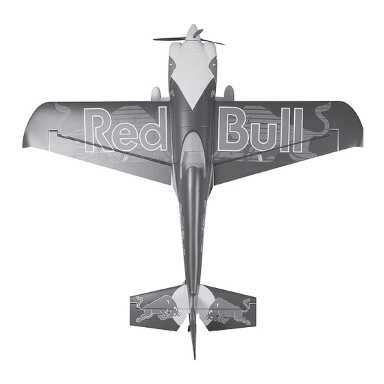
- Page 1 EDGE 540 BAUANLEITUNG INSTRUCTION MANUAL INSTRUCTIONS DE MONTAGE Art. 031-4293...
-
Page 2: Warnungen Und Sicherheitshinweise
Betriebsanleitungen im Zusammenhang mit dem Modell sowie die Installation, der Betrieb, die Verwendung und Wartung der mit dem Modell zusammenhängenden Komponenten können von der Firma Staufenbiel nicht überwacht werden. Daher übernimmt die Firma Staufenbiel keinerlei Haftung für Verluste, Schäden oder Kosten, die sich aus dem fehlerhaften Betrieb, aus fehler- haften Verhalten bzw. -
Page 3: Table Des Matières
INHALTSÜBERSICHT Vor dem Testen der Steuerfunktionen Montage des Hauptfahrwerks Testen der Steuerfunktionen Das Seitenruderscharnier Überprüfung der Drehrichtung des Motors Montage der Ruderhörner Einstellung der Steuerfunktionen Montage des Höhenruders Montage des Propellers Montage des Tragflächenübergangs Überprüfen des Schwerpunkts Montage der Tragflächen Anleitung zum Regler Einbau des Empfängers / Akku einsetzen Hinweise zum Umweltschutz... -
Page 4: Montage Des Hauptfahrwerks
MONTAGE DES HAUPTFAHRWERKS 1. Montieren Sie das Hauptfahrwerk am Rumpf wie auf den Bil- dern gezeigt. 2. Befestigen Sie die Abdeckplatte an der vorgefertigten Vertiefung im Rumpf. 3. Sichern Sie nun die Abdeckplatte mit den 4 beiliegenden Schrauben. DAS SEITENRUDERSCHARNIER 1. -
Page 5: Montage Der Ruderhörner
3. Setzen Sie nicht die Ösen an dem Seitenleitwerk ein, da diese die Bewegungsfreiheit des Ruders ein- schränken. Prüfen Sie ob die Linie A zur Linie B ausgerichtet ist und die Linie C parallel zur Linie D. Korrigieren Sie die Position des Ruders falls nötig. 4. -
Page 6: Montage Des Höhenruders
MONTAGE DES HÖHENRUDERS 1. Stecken Sie die linke Höhenruderhälfte mit dem Stier nach oben zeigend in die Öffnung am Leitwerk. 2. Schieben Sie den Leitwerksverbinder in die runde Öffnung. 3. Schieben Sie die rechte Leitwerkshälfte auf den Leitwerksverbinder. 4. Setzen Sie das Sei- tenruder ein. -
Page 7: Montage Des Tragflächenübergangs
MONTAGE DES TRAGFLÄCHENÜBERGANGS 1. Setzen Sie den Tragflächenübergang vor dem Kleben ein. Der Übergang sollte exakt zur Rumpfform passen. 2. Sollten Sie die falsche Seite genommen haben, wird die Übergangs- zu Rumpfform wie auf dem Foto zu sehen nicht übereinstimmen. Tipp: Die falsche Seite läßt sich auch viel schwieri- ger einsetzen. -
Page 8: Montage Der Tragflächen
MONTAGE DER TRAGFLÄCHEN 1. Drehen Sie den Rumpf auf den Rücken, so dass die Unterseite nach oben zeigt. Schieben Sie die rechte Tragflächenhälfte an die Tragflächenauflage und führen dabei das Querruderservokabel in den Rumpf. 2. Stecken Sie den Tragflächenverbinder in die runde Öffnung im Rumpf und in die Tragfläche. -
Page 9: Einbau Des Empfängers / Akku Einsetzen
Schieben Sie den Flugakku mit den Kabeln Richtung hinteres Ende des Flugzeugs in das Akkufach und befestigen Sie ihn mit Hilfe des Klettbands. Hinweis: Möglicherweise müssen Sie den Akku nachträglich nochmal verschieben um den richtigen Schwerpunkt Ihrer Edge 540 zu erreichen. -
Page 10: Montage Der Anlenkungen
MONTAGE DER ANLENKUNGEN 1. Die 4 mitgelieferten Anlenkungen sind für Seiten-, Höhen- und die Querruder vorgesehen. 2. Schieben Sie die Anlenkung in das 2. Loch des Servohorns. 3. Schieben Sie die nun Anlenkung auf das Ruder- horn. Das vorgesehene Stück Kraftstoffschlauch hält die Verbindung während des Fluges geschlossen. - Page 11 Sollte der Motor in die falsche Richtung drehen, tauschen Sie zwei der drei Motoranschluss- kabel um die Richtung wieder zu ändern. 3. Der Regler ist mit einer optionalen Bremse ausgestattet. Wir empfehlen die EDGE 540 mit der deaktivierten Bremse zu fliegen. Es möglich die Bremse versehentlich zu aktivieren wenn der Akku mit dem Regler verbunden wird und der Gashebel auf Vollgas steht.
-
Page 12: Testen Der Steuerfunktionen
TESTEN DER STEUERFUNKTIONEN Bevor Sie mit diesem Schritt beginnen, binden Sie bitte der Anleitung ihres Senders entsprechend den Empfänger mit dem Sender. ACHTUNG: Um mögliche Verletzungen zu vermeiden darf der Propeller bei dem Testen der Ruder NICHT auf der Welle montiert sein. Armieren Sie den Regler NICHT und schalten auch nicht den Sender ein bevor es in der Anleitung des Senders vorgeben wird. - Page 13 2. Justieren Sie die Servoarme mechanisch und stellen dabei sicher, dass die Servoarme senk- recht stehen. Nutzen Sie zur Feineinstellung ggfls. die Trimmfunktion am Sender. Hinweis: Bei Computersendern können Sie auch die Subtrimmfunktion nutzen. Stellen Sie sicher, dass diese mit der normalen Trimmung auf Neutral stehen bevor sie mechanische Trim- mungen vornehmen.
- Page 14 Seitenruder: 60 bis 65mm links und rechts, gemessen an der vorderen Kante der Ausgleichsflä- che. 2. Die Einstellungen von Dual Rate und Expo sind für erfahrene Piloten der Staufenbiel Red Bull Edge 540 und basieren auf den oben beschriebenen Ruderwegen.
-
Page 15: Montage Des Propellers
MONTAGE DES PROPELLERS Hinweis: Trennen Sie den Akku vom Regler bevor Sie den Propeller montieren. Überprüfen Sie vor dem Testen den Propellers, dass Heck des Flug- zeuges sicher auf dem Boden steht und sich keine Hindernisse in der Reichweite des Propellers befin- den. - Page 16 4. Setzen Sie die Stoppmuttern in den Innenring des Spinners. Set- zen sie die obere Abdeckung auf und schrauben die längeren 22mm Schrauben ein. Achten Sie bitte auch korrekte Passung und festen Sitz. 5. Prüfen Sie nach dem Verschrauben das sich kein Spalt zwischen den beiden Spinnerplatten befindet.
-
Page 17: Überprüfen Des Schwerpunkts
ÜBERPRÜFEN DES SCHWERPUNKTS 80 mm Setzen Sie zum Ausbalancieren des Schwerpunktes des Antriebsakku ein. Richten Sie den Akku so aus, dass das Modell gerade oder mit der Nase leicht nach unten zeigt. Nach den ersten Flügen können Sie dann den Schwerpunkt nach ihren persönliche Vorlieben einrichten. - Page 18 ANLEITUNG ZUM REGLER Programmiermodus / Akustische Signale: Regler Funktionen Gas Kalibrierung (innerhalb von 4 Sek.) Bremse Bremse ein/aus Akkutyp NiCad LiPo Einstellen der Abschaltspannung Niedrig 2.8V / 50% Medium 3.0V / 60% Hoch 3.2V / 65% Wiederherstellung der Werkseinstellung Wiederherstellen Timing Setup Automatisch (7-30°) Niedrig (7-22°)
- Page 19 Erstes Einschalten des Reglers und Einstellung der automatischen Gas-Kalibrierung: Der Regler unterstütz die automatische Gas-Kalibrierung um die bestmöglich feinfühlige Ansteu- erung über den gesamten Knüppelweg Ihrer Fernsteuerung zu ermöglichen. Dieser Schritt wird automatisch durchgeführt, wenn Sie die Funktion „lernen und speichern“ auswählen. Dieses wird nur wiederholt, wenn Sie eine andere Fernsteuerung nutzen.
- Page 21 Entsorgungsdienst oder bei der Verkaufsstelle Ihres Proukts. Layout: M. Münker Übersetzung: M. Münker STAUFENBIEL Gustav Staufenbiel GmbH, Hanskampring 9, 22885 Barsbüttel, Deutschland Geschäftsführer: Klaus Breer, Jörg Schamuhn Tel.: +49 40-30061950, eMail: info@modellhobby.de, Webseite: www.modellhobby.de Copyright © Gustav Staufenbiel GmbH...
-
Page 22: Safety Precautions And Warnings
Do not use with incompatible compo- nents or alter this product in any way outside of the instructions provided by Gustav Staufenbiel GmbH. This manual contains instructions for safety, operation and maintenance. It is essential to read and follow all the instructions and warnings in the manual, prior to assembly, setup or use, in order to operate correctly and avoid damage or serious injury. - Page 23 TABLE OF CONTENTS Before control system testing Install the main landing gear The control system testing Hinge on the rudder Check the motor rotating direction Install the control horn Check the control throws Install the horizontal stabilizer Install the propeller Install the main wing fillet Check the C.G.
-
Page 24: Install The Main Landing Gear
INSTALL THE MAIN LANDING GEAR 1. Install the main lan- ding gear by fitting the gear into the fusela- ge fully as the picture shows. 2. Install the fairing plate to the pre-notched slot on the landing gear fai- ring base. 3. -
Page 25: Install The Control Horn
3. Do not insert the eyelets of the hinge into the vertical fin, or it will impede the free movement of the rudder, after the mounting of the rudder, check to make sure the leading edge A will align with the edge B, the leading edge C will parallel to the trailing edge D. -
Page 26: Install The Horizontal Stabilizer
INSTALL THE HORIZONTAL STABILIZER 1. Insert the port side (left) stabilizer half into the tail mounting slot with the Thunderbolt side face up. 2. Slide the horizontal connecting tube into the round hole located in the stabilizer mounting slot. 3. Slide the starboard (right) stabilizer onto the tube, make sure the stabilzer tube, the connector and the elevator connector are interlock to the relative parts at the same time. -
Page 27: Install The Main Wing Fillet
INSTALL THE MAIN WING FILLET 1. Fit the wing root fairing fillet before glue it into place, the fillet will align smoothly with the fuselage chamfer. 2. Failure to fit the fillet rightly, the fillet will not align well with the fuselage as the picture shows. Tips: It will not as easily to slide the wrong side fillet into place than the right one. -
Page 28: Mount The Main Wing
MOUNT THE MAIN WING 1. Turn over the fuselage so the bottom of the plane face up, slide the starboard wing panel into the wing mounting saddle while threading the aileron control servo lead to the fuselage. 2. Insert the main wing panel reinforcing connecting tube into the round hole on the mounted the main wing. -
Page 29: Install The Receiver / The Battery
Note: You may need to relocate the battery posi- tion to achieve the correct CG for your Edge 540 model. -
Page 30: Install The Linkage Rod
INSTALL THE LINKAGE ROD 1. The four pieces are for ailerons rudder and eleva- 2. Insert the linkage rod into the second hole of the surface control horn and snap the clevis to fix it. 3. Insert the linkage rod into the control horn. The provided piece of fuel tubing keeps the clevis closed during flight. - Page 31 IMPORTANT ESC INFORMATION 1. The ESC included with the EDGE 540 has a safe start. If the motor battery is connected to the ESC and the throttle stick is not in the low throttle or off position, the motor will not start until the throttle stick is moved to the low throttle or off position.
-
Page 32: The Control System Testing
THE CONTROL SYSTEM TESTING Before getting started, bind your receiver with your transmitter. Please refer to your Transmitter Manual for proper operation. CAUTION: To prevent personal injury, DO NOT install the propeller assembly onto the motor shaft while testing the control surfaces. DO NOT arm the ESC and do not turn on the transmitter until the Transmitter Manual instructs you to do so. - Page 33 2. Adjust the servo arms mechanically make sure all servo arms are fully vertical. If not, adjust the servo arm by using the trim function on your radio. Note: For computerized transmitters, use the servo/channel sub-trim feature to make each servo arm fully vertical.
-
Page 34: Check The Control Throws
60% 36mm left/right Note: This control throws were developed by STAUFENBIEL TEAM for the best performance of the RED BULL EDGE 540. The small mount of elevator throw on low rate is capable of extreme aerobatics. At first flight, fly the model in low rate. The first time you use high rates, be sure to fly at low to medium speeds. -
Page 35: Install The Propeller
INSTALL THE PROPELLER Caution: Disconnect the battery from the ESC be- fore installing the propeller. Before testing the pro- peller, make sure the tail of the plane is firmly on the ground and ensure there are no people or objects in the range of the propeller. - Page 36 4. Place self-locking nuts right- ly into the inboard hex notch on bottom of the spinner backplate as picture shows. Cover the cover plate on the propellers. Using the longer screws (22mm) to secure the cover plate with the propeller and spinner plate tight enough as the picture shows.
- Page 37 CHECK THE C.G. (CENTER OF GRAVITY) 80 mm / 3.15 in When balancing your model, adjust the motor battery as necessary so the model is level or slightly nose down. This is the correct balance point for your model. After the first flights the CG position can be adjusted for your personal preference.
- Page 38 ESC INSTRUCTION Programming Mode Audible Tones: ESC Functions Throttle Calibration (within the first 4 Sec.) Brake Brake On/Off Battery type NiCad LiPo Low Voltage Cutoff Threshold Low 2.8V / 50% Medium 3.0V / 60% High 3.2V / 65% Restore Factory Setup Default Restore Timing Setup Automatic (7-30°)
- Page 39 Powering up the ESC for the first time and setting the Automatic Throttle Calibration: The ESC features Automatic Throttle Calibration to attain the smoothest throttle response and re- solution throughout the entire throttle range of your transmitter. This step is done once to allow the ESC to „learn and memorize“...
- Page 41 STAUFENBIEL Gustav Staufenbiel GmbH, Hanskampring 9, 22885 Barsbüttel, Germany CEO: Klaus Breer, Jörg Schamuhn Tel.: +49 40-30061950, eMail: info@modellhobby.de, Webside: www.modellhobby.de...
-
Page 42: Précautions Et Avertissements Liés À La Sécurité
N’essayez pas de modifi er ou d’utiliser ce produit avec des composants incompatibles hors des instructions fournies par Gustav Staufenbiel GmbH. Ce manuel comporte des instructions relatives à la sécurité, au fonctionnement et à l’entretien. Il est capital de lire et de respecter la totalité... -
Page 43: Caractéristiques
TABLE DES MATIÈRES Avant d‘effectuer le test des commandes Installation du train d‘atterrissage Test des commandes Installation de la dérive Contrôle de la direction de rotation du Installation du guignol moteur Installation du stabilisateur Vérifications des débattements Installation des karmans d‘aile Assemblage de l‘hélice Installation de l‘aile Contrôle du centre de gravité... -
Page 44: Installation Du Train D'atterrissage
INSTALLATION DU TRAIN D‘ATTERRISSAGE 1. Installez le train d‘atterrissage en insé- rant la boucle supérieure dans le fuselage comme indiqué sur la photo. 2. Insérez le carénage dans le support du train. 3. Fixez le carénage en position à l‘aide des 4 vis incluses dans le sachet du carénage. -
Page 45: Installation Du Guignol
3. Ne pas insérer les charnières jusqu‘à leurs œillets dans la partie fixe de la dérive, la liberté de rotation de la gouverne serait altérée. Durant la pose de la gouverne de dérive veuillez contrôler que le bord d‘attaque A est aligné par rapport au B, que le bord d‘attaque C est parallèle au bord de fuite D. -
Page 46: Installation Du Stabilisateur
INSTALLATION DU STABILISATEUR 1. Insérez le demi stabilisateur gauche dans le fuse- lage, la face du taureau sur le dessus. 2. Glissez la clé de stabilisateur dans l‘ouverture ron- de située dans le logement du stabilisateur à l‘arrière du fuselage. 3. -
Page 47: Installation Des Karmans D'aile
INSTALLATION DES KARMANS D‘AILE 1. Effectuez un positionnement à blanc du karman, il doit parfaitement s‘aligner sur le fuselage par rapport au logement de l‘aile. 2. Si le karman que vous tentez d‘installer n‘est pas celui du côté approprié il ne s‘alignera pas par rap- port au fuselage, comme indiqué... -
Page 48: Installation De L'aile
INSTALLATION D‘AILE 1. Retournez le fuselage de manière à accéder au dessous, glissez la demie aile droite dans son loge- ment en insérant la prise du servo d‘aileron dans le fuselage. 2. Insérez la clé d‘aile dans le fuselage et dans la demie aile déjà... -
Page 49: Installation Du Récepteur
INSTALLATION DU RÉCEPTEUR 1. Connectez les prises des servos des ailerons au cordon Y situé dans le fuselage. Remarque : Les servos des ailerons se connec- tent indifféremment aux deux sorties du cordon Y. 2. Connectez le cordon Y des ailerons à la voies des ailerons du récepteur. -
Page 50: Installation Des Tringleries
INSTALLATION DES TRINGLERIES 1. Les 4 tringleries sont pour les ailerons, la dérive et la profondeur. 2. Insérez la tringlerie dans le 2 ème trou du bras de servo et clip- sez le verrou pour fixer la tringlerie. 3. Connectez la chape de la tringlerie au guignol de commande. -
Page 51: Avant D'effectuer Le Test Des Commandes
INFORMATIONS IMPORTANTES RELATIVES AU CONTRÔLEUR 1. Le contrôleur inclus avec le EDGE 540 possède une sécurité de démarrage. Si la batterie de l‘avion est connectée et que le manche des gaz n‘est pas en position basse ou que l‘émetteur est hors tension, le moteur ne démarrera pas. -
Page 52: Test Des Commandes
TEST DES COMMANDES Avant de commencer, veuillez effectuer l‘affectation de votre émetteur à votre récepteur. Veuillez consulter le manuel de votre émetteur pour effectuer cette opération. ATTENTION : Afin d‘éviter des blessures corporelles, NE PAS installer l‘hélice sur l‘axe du moteur pour effectuer le test des gouvernes. -
Page 53: Contrôle De La Direction De Rotation Du
2. Réglez mécaniquement la position des bras de servo de manière qu‘ils soient totalement ver- ticaux. Si ce n‘est pas possible mécaniquement, utilisez les trims de votre radio pour affiner le réglage. Remarque : Dans le cas de l‘utilisation d‘un émetteur programmable, utilisez la fonction de sub-trim de votre émetteur pour placer chaque bras de servo à... -
Page 54: Vérifications Des Débattements
60% 36mm v. la gauche/droite Remarque : Ces valeurs ont été déterminées par l‘équipe STAUFENBIEL afin d‘offrir les meil- leurs performances au EDGE 540 RED BULL. La faible course de la profondeur en petit débat- tement permet déjà d‘effectuer des figures acrobatiques extrêmes. -
Page 55: Assemblage De L'hélice
ASSEMBLAGE DE L‘HÉLICE Attention : Déconnectez la batterie du contrôleur avant d‘installer l‘hélice. Avant de procéder au test de l‘hélice, assurez-vous que la queue de l‘avion est fermement maintenue au sol et qu‘aucune personne ou objet se trouve dans le champs de rotation de l‘hélice. - Page 56 4. Insérez les écrous frein dans les empreintes intérieures du flasque arrière du cône. Placez la partie avant du moyeu sur le flasque arrière du cône. Vissez les 3 vis de 22mm au travers de la partie avant du moyeu. 5.
-
Page 57: Contôle Du Centre De Gravité
CONTÔLE DU CENTRE DE GRAVITÉ 80 mm / 3.15 in Ajustez la position de la batterie afin d‘équilibrer le modèle ou d‘obtenir le nez légèrement plon- geant. Après avoir effectué les premier vols, vous pourrez ajuster le CG à votre convenance. 1. -
Page 58: Paramètres Du Contrôleur
PARAMÈTRES DU CONTRÔLEUR Programmation par tonalités : Fonctions du contrôleur Calibration des gaz Durant les 4 premières secondes Frein On/Off Type de batterie NiCad LiPo Seuil de coupure basse tension Basse 2.8V / 50% Moyenne 3V / 60% Haute 3.2V / 65% Restauration paramètres par défaut Restore Réglage de l‘avance... - Page 59 Mise sous tension du contrôleur pour la première fois et réglage de la calibration automa- tique des gaz: Le contrôleur dispose d‘une calibration automatique des gaz pour atteindre une réponse de l‘accélérateur plus douce et de la résolution sur toute la plage des gaz de votre émetteur. Cette étape est effectuée une fois pour permettre au contrôleur d‘...
-
Page 61: Instructions Relatives À L'élimination Des D3E
Layout: M. Münker Traduction: A. Couturier STAUFENBIEL Gustav Staufenbiel GmbH, Hanskampring 9, 22885 Barsbüttel, Allemagne Directeur général: Klaus Breer, Jörg Schamuhn Tel.: +49 40-30061950, eMail: info@modellhobby.fr, Webseite: www.modellhobby.fr Copyright © Gustav Staufenbiel GmbH... - Page 64 © 2015 Gustav Staufenbiel GmbH...