Table des Matières
Publicité
Les langues disponibles
Les langues disponibles
Liens rapides
Publicité
Table des Matières

Manuels Connexes pour Staufenbiel HSF0314076


Sommaire des Matières pour Staufenbiel HSF0314076
- Page 1 BAUANLEITUNG INSTRUCTION MANUAL INSTRUCTIONS DE MONTAGE HSF0314076 / HSF0314076P...
-
Page 2: Warnungen Und Sicherheitshinweise
Betriebsanleitungen im Zusammenhang mit dem Modell sowie die Installation, der Betrieb, die Verwendung und Wartung der mit dem Modell zusammenhängenden Komponenten können von der Firma Staufenbiel nicht überwacht werden. Daher übernimmt die Firma Staufenbiel keinerlei Haftung für Verluste, Schäden oder Kosten, die sich aus dem fehlerhaften Betrieb, aus fehler- haften Verhalten bzw. -
Page 3: Technische Daten
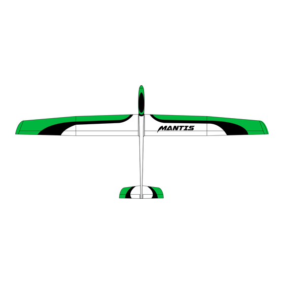
INHALTSÜBERSICHT Vorwort Montageabschluss Die Flächen Ruderausschläge Servostecker und Multilock Schwerpunkt Rumpfeinbauten Konformitätserklaärung TECHNISCHE DATEN Tragfflächen-Profil: HQ 2,5 / 9 2900 mm (114 in) 68,0 dm² 2300 g (1054 in²) (82 oz) BENÖTIGTES ZUBEHÖR LiPo 2400-3000mAh 3S GTX-3546 (910 kV) LiPo Ladegerät 60 A min. - Page 4 VORWORT Herzlichen Glückwunsch zum Erwerb des Staufenbiel MANTIS. Es handelt sich um ein leistungs- fähiges Thermikmodell mit GFK Rumpf und Styro-Abachi Flächen. Der Schwerpunkt liegt auf Ther- mikflug, durch die steifen Flächen ist aber auch leichter Kunstflug kein Problem. Die Bauausführung des Modells und die damit verbundene Detaillösungen unterliegen einer gewissen Geschmacksab-...
- Page 5 Bohren Sie für das Querruderhorn senkrecht ein Loch in das Querruder und kleben Sie das Ruderhorn wie auf dem Bild zu sehen mit Epoxy ein. Erstellen Sie ein Gestänge, stellen Sie die passende Länge ein und hängen Sie es in Servo und Ruder- horn ein.
- Page 6 Für das Ruderhorn ein Loch in die Wölbklappe bohren. Der Bohrer wird dabei 45° zur Oberfläche angesetzt. Kleben Sie das Ruderhorn anschlie- ßend mit Epoxy in die Wölbklappe ein wie im Bild zu sehen. Ziehen Sie eine Servoverlänge- rung durch die Fläche. Kleben Sie anschließend den Servorahmen mit Epoxy in die Fläche ein.
- Page 7 Hängen Sie das Gestänge nun auch im Ruderhorn ein. Schneiden Sie die Abdeckungen zu- recht und kleben Sie diese mit Tesa auf. SERVOSTECKER UND PARITECH U-PAT fehlen wir das Paritach U-Pat System. Löten Sie MPX-Stecker an die Servokabel.
- Page 8 Fertigen Sie einen Kabelbaum an. Ziehen Sie Ihn durch den Rumpf und kleben Sie den MPX-Stecker bündig in die Flächenanformung ein. Den Stecker vorher anschleifen oder mit einem Bastelmesser einritzen. Kleben Sie den Rumpf um den MPX- Stecker mit Tesa ab. MPX-Stecker anschleifen oder einritzen.
- Page 9 RUmpFEINBAUTEN Bereiten Sie die 2 Rumpfservos für den Einbau vor wie auf dem Bild zu sehen. Montieren Sie je einen Ge- stängeschnluss in den später die Schubstangen des V-Leitwerkes befestigt werden. Bohren Sie die Schraubenlöcher vor. Setzen Sie die Servos wie im Bild zu sehen ein und schrauben Sie sie fest.
- Page 10 Der Schwerpunkt befindet sich 85 - 89 mm hinter der Nasenleiste. ABSCHLUSS Genießen Sie nun den Erstflug mit Ihrem neuen Staufenbiel MANTIS. Mit den Angaben aus dieser Anleitung hält das Modell keine bösen Überraschungen parat. Die Wölbklappen können für beson- ders hohe Wendigkeit zu den Querrudern zugemischt werden.
-
Page 11: Konformitätserklärung
KONFORMITÄTSERKLÄRUNG Horizon Hobby GmbH erklärt hiermit, dass dieses Produkt konform zu den essentiellen Anforderungen der EMC Direktive. Eine Kopie der Konformitätserklärung ist online unter folgender Adresse verfügbar : http://www.horizonhobby.com/content/support-render-compliance HINWEISE ZUM UMWELTSCHUTZ Dieses Produkt darf nicht mit anderem Abfall entsorgt werden. Stattdessen obliegt es dem Benutzer, das Altgerät an einer designierten Recycling-Sammelstelle für elektrische und elektronische Gerä... -
Page 12: Safety Precautions And Warnings
Do not use with incompatible compo- nents or alter this product in any way outside of the instructions provided by Gustav Staufenbiel GmbH. This manual contains instructions for safety, operation and maintenance. It is essential to read and follow all the instructions and warnings in the manual, prior to assembly, setup or use, in order to operate correctly and avoid damage or serious injury. -
Page 13: Needed To Complete
TABLE OF CONTENTS Preface Assemby completion The wings Control throws Servo connectors and Multilock Center of gravity The fuselage Declaration of comfirmity SpECIFICATIONS Airfoil: HQ 2,5 / 9 2900 mm (114 in) 68,0 dm² 2300 g (1054 in²) (82 oz) NEEDED TO COmpLETE LiPo 2400-3000mAh 3S GTX-3546 (910 kV) - Page 14 Thanks for purchasing the Staufenbiel Mantis. It is a high performance thermal glider with composite fuselage and obechi sheeted wings with a foam core. The focus is on thermal gliding, but due to the stiff wings light aerobatics are also no problem. The construction of the model and the detailed solu- tions related subject to a certain taste dependency.
- Page 15 Drill a vertical hole into the aileron for the aileron horn and glue in the horn with epoxy glue like shown in the picture. Prepare a pushrod with the needed length and clip in the clevis in the servo horn and the aileron horn. Beforehand bring the Aileron into neutral position as well as the servo in electronical midle position.
- Page 16 Drill a hole in the flap for the horn. Drill in a 45° angle to the surface. Afterwards glue the horn in the flap with epoxy glue like shown in the picture. Pull a servo extension through the wing. Afterwards glue the servo frame in with epoxy glue.
- Page 17 Now clip in the linkage in the control horn. Cut the servo covers to the desired shape and glue them to the wing with clear tape. SERVO CONNECTOR AND PARITECH U-Pat To secure the wings to the fuselage we recommend the U-Pat system from Paritech.
- Page 18 Create a cable beam. Pull it through the fuselage and glue in the MPX- glueing sand the connector or make some cuts with a hobby knife. Tape the fuselage around the MPX- connector. Sand the connector or make some cuts with a hobby knife. Afterwards put some epoxy glue on the marked parts behind the connector and mount the wing and let the epoxy...
- Page 19 THE FUSELAGE Prepare the two fuselage servos for installation like shown in the picture. Drill the screw holes. Install the servo like shown in the picture and screw the self tapping screws. Make a mark for the screw holes of the V-Tail and drill them open with a 3 mm drill.
-
Page 20: Control Throws
Afterwards drive the servos to the electronic middle position. Hold the halfs of the V-tail in neutral position and tighten the grubscrew of the linkage connector. ASSEmBLY COmpLETION At the end the ESC, the motor and the receiver needs to be built in. Start programming the model in the transmitter. -
Page 21: Declaration Of Conformity
DECLARATION OF CONFORMITY EU Compliance Statement: Horizon Hobby, LLC hereby declares that - this product is in compliance with the essential requirements and other relevant provisions of the EMC Directive. A copy of the EU Declaration of Conformity is available online at: http://www.horizonhobby.com/content/support-render-compliance. -
Page 22: Précautions Et Avertissements Liés À La Sécurité
N’essayez pas de modifi er ou d’utiliser ce produit avec des composants incompatibles hors des instructions fournies par Gustav Staufenbiel GmbH. Ce manuel comporte des instructions relatives à la sécurité, au fonctionnement et à l’entretien. Il est capital de lire et de respecter la totalité... -
Page 23: Caractéristiques
TABLE DES mATIÈRES Préface Fin de l‘assemblage Les ailes Débattements des gouvernes Prises des servos et système Multilock Centre de gravité Le fuselage Déclaration de conformité CARACTÉRISTIQUES Profil: HQ 2,5 / 9 2900 mm (114 in) 68,0 dm² 2300 g (1054 in²) (82 oz) ELÉmENTS REQUIS... -
Page 24: Les Ailes
Nous vous remercions pour l‘achat du Mantis Staufenbiel. Il s‘agit d‘un planeur hautes-performances possédant un fuselage en fibre de verre et des ailes en mousse coffrées obechi. Conçu à la base pour le vol thermique, ses ailes rigides permettent d‘effectuer de la voltige douce. L‘assemblage du modèle et les solutions détaillées rapportées sont à... - Page 25 Percez un trou vertical dans l‘aileron pour y installer le guignol de com- mande et collez-le en place à l‘aide de colle Epoxy comme sur la photo. Préparez la tringlerie à la longueur appropriée et connectez les chapes au bras de servo et au guignol. En ayant préalablement mis le servo et la gouverne au neutre.
- Page 26 Percez un trou dans le volet pour y installer le guignol. Le trou est incliné à 45° par rapport à la surface. Collez le guignol au volet en utilisant de la colle Epoxy, comme sur la photo. Tirez une rallonge de servo dans l‘aile.
- Page 27 Maintenant vous pouvez connecter la tringlerie au guignol du volet. Découpez les carénages de servos à à l‘aide d‘adhésif transparent. PRISES DES SERVOS ET SYSTÈME U-Pat vous recommandons d‘utiliser le système Paritech U-Pat. Soudez une prise MPX aux ral longes de servos.
- Page 28 Créez un faisceau de câbles. Tirez le à l‘intérieur du fuselage et collez la prise Multiplex à fleur du fuselage. Avant de coller la prise, prenez soin de la poncer ou de la gratter à l‘aide d‘un scalpel. Recouvrez le fuselage d‘adhésif de masquage autour de la prise multi- plex.
- Page 29 LE FUSELAGE Préparez 2 servos comme sur la photo pour leur installation dans le fuselage. Percez les trous de fixation des ser- vos. Installez les servos comme indiqué sur la photo et utilisez des vis auto- taraudeuses pour assurer leur fixati- Marquez l’emplacement des trous des vis et effectuez le perçage de ceux -ci avec un foret de 3 millimètres.
-
Page 30: Fin De L'assemblage
Placez les servos au neutre. Main- tenez les gouvernes au neutre et serrez les vis des connecteurs de tringleries. FIN DE L‘ASSEmBLAGE Maintenant vous pouvez installer le contrôleur, le moteur et le récepteur. Programmez le modèle dans votre émetteur. Connectez les servos à votre récepteur en respectant les consignes du manuel de votre radio. -
Page 31: Déclaration De Conformité
DÉCLARATION DE CONFORMITÉ Ce produit respecte les exigences de protection essentielles de directives de l‘Union européenne quant à la compatibilité électromagnétique. Une Déclaration de Conformité est disponible. INSTRUCTIONS RELATIVES À L‘ÉLIMINATION DES D3E Ce produit ne doit pas être éliminé avec d’autres déchets. Il relève de la responsabilité de l’utilisateur d’éliminer les équipements rebutés en les remettant à... - Page 32 © 2015 Gustav Staufenbiel GmbH...