
Manuels Connexes pour Allmatic BIOS1 24V


Sommaire des Matières pour Allmatic BIOS1 24V
- Page 1 All manuals and user guides at all-guides.com BIOS1 24V CENTRALINA PER CANCELLI SCORREVOLI 24V MADE IN ITALY...
- Page 2 ATTENZIONE! Prima di installare il prodotto è obbligatorio leggere il documento relativo alle AVVERTENZE DI SICUREZZA GENERALI a corredo del prodotto. Documento 6-1620001. Il foglio integrativo è scaricabile anche dal sito www.allmatic.com. 2 - SELEZIONE MOTORIZZAZIONE IN USO ATTENZIONE! Prima di eseguire gli apprendimenti delle corse, la memorizzazione dei trasmettitori e prima di eseguire qualsiasi altra impostazione, è...
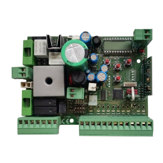
- Page 3 3 - DESCRIZIONE PRODOTTO La centrale di comando BIOS1 24V è indicata per le installazioni a 1 motore 24Vdc e un assorbimento massimo di 10A. Il suo funzionamento è facile e intuitivo grazie all’interfaccia display e ai 4 tasti. Il quadro di comando permette una regolazione precisa di tutti i parametri. La centrale può memorizzare fino a 1000 trasmettitori (memoria esterna) con la funzione passo passo, apertura parziale, apri e chiudi.
- Page 4 All manuals and user guides at all-guides.com 3.2 - MODELLI E CARATTERISTICHE TECNICHE CODICE DESCRIZIONE 12006685 Centrale BIOS1 24V per un motore 60550058 Trasformatore 230 / 23 Vac 150VA 12006730 Modulo Bluetooth 12000760 Scheda R1 12000780 Scheda carica batterie 24CBA...
- Page 5 All manuals and user guides at all-guides.com N.B. Eliminare i fermi meccanici del tipo descritto in Fig. 3. Non devono essere presenti fermi meccanici al di sopra del cancello perché non sono sufficientemente sicuri. Componenti da installare secondo la norma EN12453 USO DELLA CHIUSURA Persone esperte TIPO DI COMANDO...
- Page 6 All manuals and user guides at all-guides.com 4.1 - ELENCO MORSETTI E CONNETTORI Numero Nome Descrizione 1 - 2 FLASH Uscita lampeggiante a 24Vac. Utilizzare un lampeggiante senza autolampeggio 24Vac 25W max. 3 - 4 Uscita luce di cortesia / spia automazione aperta a 24Vac. Utilizzare una luce 24Vac 25W max.
- Page 7 All manuals and user guides at all-guides.com 5 - DISPLAY E STATI DELLA CENTRALE DOWN MENU Premendo il tasto “DOWN” si possono leggere sul display i seguenti parametri. DISPLAY DESCRIZIONE Visualizzazione stato (--, OP, CL, ...) Descrizione dello stato della centrale. Fare riferimento alla tabella STATI DELLA CENTRALE per la descrizione dei singoli stati di funzionamento.
- Page 8 All manuals and user guides at all-guides.com 5.3 - SEGNALAZIONI ANOMALIE DISPLAY DESCRIZIONE Errore memoria: memoria esterna non montata o non riconosciuta. Errore scrittura memoria: il valore x è un numero da 1 a 6. In caso di errore contattare l’assistenza tecnica. Errore finecorsa: finecorsa di apertura e chiusura occupati contemporaneamente.
- Page 9 L’apprendimento di un trasmettitore può essere attivato tramite il tasto “UP” della centralina o tramite il tasto nascosto di un trasmettitore già memorizzato. La centrale BIOS1 24V può memorizzare fino a 4 funzioni in altrettanti tasti del radiocomando. Durante la procedura d’apprendimento, illustrata al DOWN paragrafo 6.1, si memorizza il singolo tasto del trasmettitore.
- Page 10 DOWN MENU All manuals and user guides at all-guides.com 6.2 - APPRENDIMENTO CON IL TASTO NASCOSTO DI UN TRASMETTITORE GIÀ APPRESO DOWN MENU MENU DISPLAY Lampeggiante Ad automazione ferma premere con l’aiuto di una graffetta il tasto nascosto di DOWN ...
- Page 11 All manuals and user guides at all-guides.com 7 - APPRENDIMENTO DELLA CORSA NOTA - prima di effettuare l’apprendimento verificare tramite il menu avanzato de.f. (capitolo 9) se il tipo di motore selezionato è corretto. Alla prima accensione è necessario eseguire una procedura di apprendimento per rilevare la lunghezza della corsa e dei rallentamenti. Dopo questa procedura l’installazione è...
- Page 12 All manuals and user guides at all-guides.com 7.2 - APPRENDIMENTO AVANZATO Assicurarsi di aver montato i finecorsa elettrici e di averli correttamente regolati. Effettuare un controllo delle impostazioni ed eventualmente personalizzarle prima di effettuare l’apprendimento. Assicurarsi di aver impostato il menu LSI = P. I rallentamenti dovranno essere impostati durante la procedura di apprendimento e le ampiezze nelle due direzioni saranno indipendenti.
- Page 13 All manuals and user guides at all-guides.com 8 - MODIFICA PARAMETRI - MENU BASE DOWN È possibile accedere a un MENU BASE per la modifica dei parametri principali dell’unità di controllo. DOWN MENU Per entrare nel menu, procedere come sotto riportato. MENU ATTENZIONE - dopo 2 minuti di inattività...
- Page 14 All manuals and user guides at all-guides.com DEFAULT PARAMETRI DESCRIZIONE UNITÀ CUSTOM Ampiezza rallentamento: P = personalizzato da apprendimento. 0…100% = percentuale della corsa. Antislittamento / Tempo extra. NOTA - i parametri evidenziati in grigio dipendono dal motore selezionato. In tabella vengono riportati i dati del motore CUSTOM. Per maggiori dettagli fare riferimento al capitolo 11.
- Page 15 All manuals and user guides at all-guides.com 9 - MODIFICA PARAMETRI - MENU AVANZATO DOWN Questo menu permette una personalizzazione più dettagliata di alcuni parametri. MENU Per entrare, premere e mantenere premuto il tasto “MENU” per almeno 5 secondi. Per modificare i parametri si procede come indicato per il menu base. ATTENZIONE - dopo 2 minuti di inattività...
- Page 16 All manuals and user guides at all-guides.com DEFAULT PARAMETRI DESCRIZIONE UNITÀ CUSTOM Soglia cicli richiesta assistenza. Raggiunta la soglia impostata i cicli x 1000 successivi verranno eseguiti con lampeggio veloce (solo se FPr è attivo). cicli 0 = disabilitato. Abilitazione al lampeggio continuo per richiesta assistenza (funzione eseguita solo ad automazione chiusa): 0 = disabilitato.
- Page 17 All manuals and user guides at all-guides.com La fotocellula di apertura ha il seguente funzionamento: • Apertura: ferma il moto dell’automazione ed attende che il fascio venga liberato, quindi riparte in apertura. • Chiusura: – ph.2. = 0 ferma il moto dell’automazione ed attende che il fascio venga liberato, quindi riparte in apertura. –...
- Page 18 All manuals and user guides at all-guides.com ATTENZIONE - non utilizzare con i cancelli scorrevoli. 23. RILASSAMENTO MECCANICA Mr.E. Funzione per il rilassamento della meccanica dei motori: è utile in quei motori in cui lo sblocco per il movimento manuale può rimanere bloccato a causa della pressione del motore sul finecorsa meccanico.
- Page 19 All manuals and user guides at all-guides.com DOWN DOWN DOWN DOWN DOWN DOWN 10 - ECOMODE MENU MENU MENU MENU MENU MENU La funzione ECOMODE permette di aumentare la durata delle batterie in caso di mancanza di tensione di rete. Per abilitare la funzione: ...
- Page 20 All manuals and user guides at all-guides.com 11 - VALORI DI DEFAULT La centralina BIOS1 24V ha la possibilità di selezionare il modello del motore utilizzato. Questo permette di configurare di default alcuni parametri per il funzionamento ottimale del motore.
- Page 21 All manuals and user guides at all-guides.com BIOS1 24V CONTROL UNIT FOR SLIDING GATES AT 24V MADE IN ITALY...
- Page 22 WARNING! Before installing the product, it is mandatory to read the document relating to GENERAL SAFETY WARNINGS supplied with the product. Document 6-1620001. The supplementary sheet can also be downloaded from www.allmatic.com. 2 - SELECTION OF THE MOTOR WARNING! Before executing the learning of the strokes, the memorization of the transmitters and before performing any other setting, it is necessary to select the motorization in use, this allows to optimize the operation of BIOS1 24.
- Page 23 All manuals and user guides at all-guides.com 3 - PRODUCT DESCRIPTION The control unit BIOS1 24V is suitable for the installations of 1 motor with direct current 24V and a maximum absorption of 10A. This device has an easy and intuitive functioning thanks to the display interface and 4 buttons. The control unit allows a precise regulation of all parameters. The control unit can memorize up to 1000 transmitters (external memory) with the step by step, partial opening, open and close functions.
- Page 24 All manuals and user guides at all-guides.com 3.2 - MODELS AND TECHNICAL FEATURES CODE DESCRIPTION 12006685 BIOS1 24V control unit for a single motor 60550058 Transformer 230 / 23 Vac 150VA 12006730 Bluetooth module 12000760 R1 card 12000780 Battery charger 24CBA card...
- Page 25 All manuals and user guides at all-guides.com to avoid the unintentional gate release. Note: Eliminate the mechanical stops of the kind described by Fig. 3. No mechanical stop shall be on top of the gate, since mechanical stops are not safe enough. Parts to install meeting the EN 12453 standard USE OF THE SHUTTER Skilled persons...
- Page 26 All manuals and user guides at all-guides.com 4.1 - LIST OF TERMINAL BOARDS AND CONNECTORS Number Name Description 1 - 2 FLASH Flashing light output at 24Vac. Use a flashing light without self flashing card 24Vac 25W max. 3 - 4 Courtesy light / Open automation light output at 24Vac.
- Page 27 All manuals and user guides at all-guides.com 5 - DISPLAY AND STATES OF THE CONTROL UNIT DOWN MENU By pressing the “DOWN” button it is possible to read on the display the following parameters. DISPLAY DESCRIPTION State showing (--, OP, CL, ...) Description of the control unit state.
- Page 28 All manuals and user guides at all-guides.com 5.3 - MALFUNCTION SIGNALLINGS DISPLAY DESCRIPTION Memory error: the external memory not installed or not recognised. Memory error during the writing: the value x is a number from 1 to 6. In the event of the error, contact the technical assistance. Limit switches error: opening and closing limit switches are busy in the same time DISPLAY Impact sensor intervention.
- Page 29 The learning of a transmitter can be enabled with the “UP” button of the control unit or with the hidden key of a transmitter already memorized. The BIOS1 24V control unit can memorize up to 4 functions in as many keys of the remote control. During the learning procedure, described at DOWN paragraph 6.1, a single key is stored.
- Page 30 DOWN MENU All manuals and user guides at all-guides.com 6.2 - LEARNING WITH THE HIDDEN KEY OF A TRANSMITTER ALREADY MEMORIZED DOWN MENU MENU DISPLAY Blinker With the automation steady, with the aid of a clip press the hidden key of a DOWN ...
- Page 31 All manuals and user guides at all-guides.com 7 - SETTING OF THE STROKE NOTE - check with the advanced menu de.f.(chapter 9) if the selected motor type is correct, before carring out the learning. At the first power up, it is necessary to carry out a learning of the stroke for the acquisition of the stroke length and the slowdowns. After this procedure the installation is complete.
- Page 32 All manuals and user guides at all-guides.com 7.2 - ADVANCED SETTINGS OF THE STROKE Be sure that the limit switches are connected and correctly adjusted. Carry out a check of the menus and, if needed, customize the settings before the learning of the stroke. ...
- Page 33 All manuals and user guides at all-guides.com 8 - CHANGE PARAMETERS - BASIC MENU DOWN It is possible to access a BASIC MENU to change the main parameters of the control unit. DOWN MENU To enter the menu, proceed as described below. MENU WARNING - after 2 minutes of inactivity, the control unit exits automatically from the menu.
- Page 34 All manuals and user guides at all-guides.com DEFAULT PARAMETERS DESCRIPTION UNIT CUSTOM Amplitude of slowdown. P = personalized during learning. 0…100% = percentage of stroke. Anti slipping / Extra time. NOTE - the parameters highlighted in grey depend on the selected motor. In the table are reported the data of the CUSTOM motor. For more information, refer to chapter 11.
- Page 35 All manuals and user guides at all-guides.com 9 - CHANGE PARAMETERS - ADVANCED MENU DOWN This menu allows a more detailed setting of some parameters. MENU To enter the ADVANCED MENU, press and hold the “MENU” button for at least 5 seconds. To change the parameters, proceed as described for the BASIC MENU.
- Page 36 All manuals and user guides at all-guides.com DEFAULT PARAMETERS DESCRIPTION UNIT CUSTOM Threshold of cycles for assistance request. Once the limit is reached the x 1000 next cycles will be done with fast blinking (only if FPr enabled). cycles 0 = disabled. Continuous blinking for assistance request (done only with closed automation): 0 = disabled.
- Page 37 All manuals and user guides at all-guides.com The opening photocell has the following functioning: • Opening: stops the movement and waits until the beam is freed, then moves in opening. • Closing: – ph.2. = 0 stops the movement and waits until the beam is freed, then moves in opening. –...
- Page 38 All manuals and user guides at all-guides.com WARNING - Do not use with sliding gates. 23. MECHANICAL RELAXATION Mr.E. Function for the mechanical relaxation of the motor: it is useful on those motors that have the unlock for the manual movement which can remain locked due to the pressure of the motor on the mechanical stop.
- Page 39 All manuals and user guides at all-guides.com DOWN DOWN DOWN DOWN DOWN DOWN 10 - ECOMODE MENU MENU MENU MENU MENU MENU The ECOMODE function allows to increase the batteries life in the event of a black-out of the grid. To enable the function: ...
- Page 40 All manuals and user guides at all-guides.com 11 - DEFAULT VALUES The BIOS1 24V control unit has the possibility to select the used motor. This allows to set, as defaults, some parameters for the optimal functioning of the motor. Here below, the table of the parameters with the default values assigned that depend on the motor.
- Page 41 All manuals and user guides at all-guides.com BIOS1 24V CENTRAL DE COMMANDE POUR PORTAIL COULISSANT À 24V MADE IN ITALY...
- Page 42 ATTENTION! Avant d’installer le produit il est obligatoire de lire le dossier concernant LES AVVERTISSEMENTS GÉNÉRALES DE SECURITÉ fournies avec le produit. Dossier 6-1620001. Téléchargeable aussi à partir du site internet www.allmatic.com. 2 - SÉLECTION AUTOMATISATION EN UTILISATION ATTENTION! Avant d’effectuer les apprendissages des courses, l’apprendissages des émetteurs et avant d’effectuer n’importe quoi d’autre configuration, il est necessaire de choisir l’automatisation en utilisation.
- Page 43 3 - DESCRIPTION DU PRODUIT La centrale de commande BIOS1 24V est indiquée pour les installations de 1 moteur à courant continu 24V et d’une absorption maximum de 10A. Son fonctionnement est simple et intuitif grâce à l’interface d’affichage et aux 4 boutons. Le tableau de commande permet un réglage précis de tous les paramètres.
- Page 44 All manuals and user guides at all-guides.com 3.2 - MODÈLES ET CARACTÉRISTIQUES TECHNIQUES CODE DESCRIPTION 12006685 Central de commande BIOS1 24V pour 1 moteur. 60550058 Transformateur 220 / 23 Vac 150VA. 12006730 Module Bluetooth. 12000760 Carte R1. 12000780 Carte chargeur de batteries 24CBA.
- Page 45 All manuals and user guides at all-guides.com supérieure (Fig. 3), afin d’éviter tout décrochage accidentel. Note: éliminer les arrêts mécaniques du type indiqué, décrit dans la Fig. 3. Il ne devra y avoir aucun arrêt mécanique au-dessus du portail, étant donné que les arrêts mécaniques ne sont pas suffisamment sûrs.
- Page 46 All manuals and user guides at all-guides.com 4.1 - LISTE DES BORNES ET CONNECTEURS Nombre Description 1 - 2 FLASH Sortie clignotant à 24 Vac. Utiliser un clignotant sans circuit auto-clignotement 24Vac 25W max. 3 - 4 Sortie lumière de courtoisie/voyant automation ouvert à 24Vac. Utiliser une lumière 24Vac 25W max.
- Page 47 All manuals and user guides at all-guides.com 5 - AFFICHAGE ET ÉTATS DE LA CENTRALE DOWN MENU Appuyer sur la touche “DOWN” pour lire sur l’écran les paramètres suivants. ÉCRAN DESCRIPTION Description de l’état de la centrale. Faites référence à la table ÉTATS DE Visualisation état (--, OP, CL, ...) LA CENTRALE pour la description des états de fonctionnement.
- Page 48 All manuals and user guides at all-guides.com 5.3 - SIGNALISATION ANOMALIES ÉCRAN DESCRIPTION Erreur mémoire: mémoire externe non installée ou non reconnue. Erreur écriture mémoire: la valeur x est un numéro de 1 à 6. Si une erreur se produit, contactez l'assistance technique. Erreur fin-de-course: fin de course d’ouverture et fermeture occupés au même temps.
- Page 49 L’apprentissage d’un émetteur peut être activé par le bouton “UP” de la centrale de commande, ou par la touche cachée d’un émetteur déjà mémorisé. La centrale BIOS1 24V peut mémoriser jusqu’à quatre fonctions dans autant de touches de la télécommande. Pendant la procédure d’apprentissage, expliquée au paragraphe 6.1, on mémorise le bouton individuel de l’émetteur.
- Page 50 DOWN MENU All manuals and user guides at all-guides.com 6.2 - APPRENTISSAGE PAR LA TOUCHE CACHÉE D’UN ÉMETTEUR DÉJÀ APPRIS DOWN MENU MENU DISPLAY Clignotant Quand la motorisation est arrêté, appuyer par l’aide d’une agrafe sur la touche DOWN ...
- Page 51 All manuals and user guides at all-guides.com 7 - APPRENTISSAGE DES COURSES NOTE - avant d’effectuer l’apprentissage vérifiez à travers le menu avancé de.f. (chapitre 9) si le type de moteur sélectionné est correct. Lors de la première activation il est nécessaire d’effectuer une procédure d’apprentissage pour détecter la longueur de la course et des ralentissements. Après cette procédure, l’installation est terminée.
- Page 52 All manuals and user guides at all-guides.com 7.2 - APPRENTISSAGE DES COURSES AVANCÉ S’assurer d’avoir installé les fins de course électriques et de les avoir correctement réglés. Effectuer un contrôle des réglages et éventuellement les personnaliser avant de procéder avec l’apprentissage. ...
- Page 53 All manuals and user guides at all-guides.com 8 - MODIFICATION DES PARAMETERS - MENU BASE DOWN Il est possible d’accéder au menu de base pour la modification des principaux paramètres de la centrale de commande. DOWN MENU Pour entrer dans le MENU BASE, procéder comme il suit. MENU ATTENTION - Au bout de 2 minutes d’inactivité, la centrale de commande sort automatiquement du menu.
- Page 54 All manuals and user guides at all-guides.com DEFAULT PARAMÈTRES DESCRIPTION UNITE CUSTOM Amplitude ralentissement : P = personnalisé par l’apprentissage. 0…100% = pourcentage de la course. Anti-glissement / Temps supplémentaire. NOTE - Les paramètres mis en évidence en gris dépendent du moteur sélectionné. Dans le tableau, les données du moteur CUSTOM sont représentées. Pour plus de détails faire référence au chapitre 11.
- Page 55 All manuals and user guides at all-guides.com 9 – MODIFICATION DES PARAMÈTRES - MENU AVANCÉ DOWN Ce menu permet une personnalisation plus détaillée de certains paramètres. MENU Pour entrer, appuyer et garder appuyée la touche “MENU” pendant 5 secondes. Pour modifier les paramètres, suivre les indications fournies par le MENU BASE. ATTENTION - Au bout de 2 minutes d’inactivité, la centrale de commande sort automatiquement du menu.
- Page 56 All manuals and user guides at all-guides.com DEFAULT PARAMÈTRES DESCRIPTION UNITE CUSTOM Limite cycles de requête assistance. Si la limite configurée est atteinte, les x 1000 cycles suivants seront exécutés avec clignotement rapide (seulement si FPr cycles est activé). (0 = désactivé) Habilitation au clignotement continu pour la requête d’assistance (fonction exécutée seulement avec l’automatisme fermé): 0 = désactivé.
- Page 57 All manuals and user guides at all-guides.com COMPORTEMENT PH2 Ph.2. La photocellule d’ouverture a le fonctionnement suivant: • Ouverture: arrête le mouvement de l’automatisme et attend que le faisceau soit libéré, ensuite repart en ouverture. • Fermeture: – ph.2. = 0 arrête le mouvement de la motorisation et attend que le faisceau soit libéré, ensuite repart en fermeture. –...
- Page 58 All manuals and user guides at all-guides.com accessoires 24Vdc. Voir le chapitre 10. 22. PRESSION DU MOTEUR EN ÉTAT DE FERMETURE MP.r. Fonction pour le maintien de la correcte position de fermeture totale du moteur, exécutée seulement avec la motorisation fermé. La centrale de commande actionne le moteur pendant une minute chaque mp.r.
- Page 59 All manuals and user guides at all-guides.com DOWN DOWN DOWN DOWN DOWN DOWN 10 - ECOMODE MENU MENU MENU MENU MENU MENU La fonction ECOMODE permet d’augmenter la durée de vie des batteries en cas de coupure de courant. Pour activer la fonction: ...
- Page 60 All manuals and user guides at all-guides.com 11 - VALEURS PAR DEFAULT La centrale de commande BIOS1 24V a la possibilité de sélectionner le modèle du moteur utilisé. Cela vous permet de configurer certains paramètres par défaut, pour le fonctionnement optimal du moteur.
- Page 61 All manuals and user guides at all-guides.com BIOS1 24V CUADRO DE MANDO PARA CANCELAS CORREDERAS 24V MADE IN ITALY...
- Page 62 CUIDADO! Antes de instalar el producto es obligatorio leer el documento relativo a las ADVERTENCIAS DE SEGURIDAD GENERAL en dotación con il producto. Documento 6-1620001. La página integrativa se puede descargar tambien del sitio www.allmatic.com. 2 - SELECCIÓN DE LA MOTORIZACIÓN EN USO CUIDADO! Antes de realizar los aprendizajes de los recorridos, la memorización de los mandos y antes de realizar...
- Page 63 3 - DESCRIPCIÓN DEL PRODUCTO La central de mando BIOS1 24V es indicada para la instalación de 1 motor 24 Vdc con absorción máxima de 10A. Su funcionamiento es fácil e intuitivo gracias al interfaz display y a las 4 teclas. El cuadro de mando permite una regulación precisa de todos los parámetros. La central puede memorizar hasta 1000 mandos (memoría externa) con la función paso a paso, apertura parcial, abre y cierra.
- Page 64 All manuals and user guides at all-guides.com 3.2 - MODELOS Y CARACTERÍSTICAS TÉCNICAS CÓDIGO DESCRIPCIÓN 12006685 Cuadro de mando BIOS1 24V para un motor 60550058 Transformador 230 / 23 Vac 150VA 12006730 Módulo bluetooth 12000760 Placa R1 12000780 Placa cargadora de batería 24CBA Alimentación transformador...
- Page 65 All manuals and user guides at all-guides.com anti-descarrilamiento (Fig. 3) para evitar desenganches involuntarios. Nota: Eliminar los topes mecánicos del tipo descripto en la Fig. 3. No tiene que haber topes mecánicos por encima de la cancela porque no son suficientemente seguros.
- Page 66 All manuals and user guides at all-guides.com 4.1 – INDICE BORNES Y CONECTORES Número Nome Descripción 1 - 2 FLASH Salida luz intermitente de 24Vac. Utilizar una luz intermitente sin autodestello 24Vac 25W max. 3 - 4 Salida luz de cortesía / luz indicadora automatización abierta de 24Vac. Utilizar una luz 24Vac 25W max.
- Page 67 All manuals and user guides at all-guides.com 5 - DISPLAY Y ESTADO DE LA CENTRAL DOWN MENU Presionando el pulsador “DOWN“ en la pantalla se pueden leer los siguientes parámetros: DISPLAY DESCRIPCIÓN Visualización estado (--, OP, CL, ...) Descripción del estado de la central. Hacer referencia al cuadro ESTADOS DE LA CENTRAL para la descripción de cada estado de funcionamiento.
- Page 68 All manuals and user guides at all-guides.com 5.3 - SEÑALIZACIÓN ERRORES DISPLAY DESCRIPCIÓN Error memoría: memoria externa no montada o no reconocida. Error escritura memoria: el valor x es un número de 1 a 6. En caso de error contactar la asistencia técnica. Error final de carrera: final de carrera en apertura y cierre ocupados contemporáneamente.
- Page 69 El aprendizaje de un mando puede ser activado por medio de la tecla “UP” de la central o por la tecla escondida de un mando memorizado. La central BIOS1 24V puede memorizar hasta 4 funciones otras tantas teclas del mando. Durante el procedimiento de aprendizaje, mencianado en el parágrafo 6.1, se memoriza la singular tecla del mando.
- Page 70 DOWN MENU All manuals and user guides at all-guides.com 6.2 - APRENDIZAJE CON LA TECLA ESCONDIDA DE UN MANDO YA MEMORIZADO DOWN MENU MENU DISPLAY Intermitente Con la automatización cerrada presionar con la ayuda de una grapa, la DOWN ...
- Page 71 All manuals and user guides at all-guides.com 7 - APRENDIZAJE RECORRIDO NOTA – antes de realizar el aprendizaje verificar por medio del menu avanzado de.f. (capítulo 9) si el tipo de motor seleccionado es correcto. Con el primer encendido es necesario realizar un procedimiento de aprendizaje para relevar la longitud del recorrido y de las deceleraciones. Luego este procedimento la instalación se ha realizado.
- Page 72 All manuals and user guides at all-guides.com 7.2 - APRENDIZAJE AVANZADO Asegurarse de haber montado y regulado correctamente los topes eléctricos. Efectuar un control de las regulaciones y eventualmente personalizar antes de efectuar el aprendizaje. Asegurarse de haber regulado el menú LSI = P. Las desaceleraciones deben ser reguladas durante el procedimiento de aprendizaje y las amplitudes en ambas direcciones seran independientes.
- Page 73 All manuals and user guides at all-guides.com 8 – MODIFICACION PARAMETROS - MENU BASICO DOWN Es posible acceder a un MENU BASICO para la modificación de los parámetros principales de la unidad de control. DOWN MENU Para entrar en el MENÚ BÁSICO proceda de la siguiente manera. MENU CUIDADO - la central sale del menù...
- Page 74 All manuals and user guides at all-guides.com DEFAULT PARÁMETROS DESCRIPCIÓN UNIDAD CUSTOM Amplitud desaceleración: P = personalizado de aprendizaje. 0…100% = porcentual del recorrido. Antideslizamiento / Tiempo extra. NOTA - los parámetros evidenciados en color gris dependen del motor seleccionado. En el cuadro son mencionados los datos del motor CUSTOM. Para mayores detalles remitimos al capítulo 11.
- Page 75 All manuals and user guides at all-guides.com 9 - MODIFICACION PARAMETROS - MENU AVANZADO DOWN Este menú permite una personalización más detallada de algunos parámetros. MENU Para entrar, mantener presionada la tecla “MENU” por lo menos 5 segundos. Para modificar los parámetros se procede como indicado por el menú básico. CUIDADO - la central sale del menù...
- Page 76 All manuals and user guides at all-guides.com DEFAULT PARÁMETROS DESCRIPCIÓN UNIDAD CUSTOM Umbral ciclos solicitada asistencia. Alcanzado el umbral regulado los ciclos x 1000 sucesivos seran realizados con destellos veloces (solo si FPr es activo). ciclos 0 = deshabilitado. Habilitación al destello para solicitud asistencia (función realizada solo con automatización cerrada): 0 = deshabilitado.
- Page 77 All manuals and user guides at all-guides.com La fotocélula de apertura tiene el siguiente funcionamiento: • Apertura: para el movimiento de la automatización y espera que el haz sea liberado, entonces parte nuevamente en apertura. • Cierre: – ph.2. = 0 para el movimiento de la automatización y espera que el haz sea liberado, entonces parte nuevamente en apertura. –...
- Page 78 All manuals and user guides at all-guides.com Función para el mantenimiento de la presión de los motores sobre el paro mecánico, realizada solo con el automatismo cerrado. La central activa el motor por un minuto cada mp.r. minutos con la finalidad de mantener la presión sobre los paros mecánicos. CUIDADO - no utilizar con las cancelas correderas.
- Page 79 All manuals and user guides at all-guides.com DOWN DOWN DOWN DOWN DOWN DOWN 10 - ECOMODE MENU MENU MENU MENU MENU MENU La función ECOMODE permite aumentar la duración de las baterías en caso de falta de corriente eléctrica. Para habilitar la función: ...
- Page 80 All manuals and user guides at all-guides.com 11 - VALORES DE DEFAULT La central BIOS1 24V tiene la posibilidad de seleccionar el modelo del motor utilizado. Esto permite configurar en default algunos parámetros para el funcionamiento óptimo del motor. A continuación se acompaña cuadro de los parámetros dependiente del motor con el valor de default asignado.