Table des Matières
Publicité
Les langues disponibles
Les langues disponibles
Liens rapides
Publicité
Chapitres
Table des Matières
Dépannage

Manuels Connexes pour Frigomat Kikka 1G 05 Série


Sommaire des Matières pour Frigomat Kikka 1G 05 Série
- Page 2 MACCHINE SOFT ELETTRONICHE ELECTRONIC SOFT ICE CREAM MACHINES MACHINES Á GLACE SOFT ELECTRONIQUES ELECTRONISCHE SOFTEISMASCHINEN MAQUINAS ELECTRONICAS POR HELADO SOFT MANUALE D’USO E MANUTENZIONE MANUAL OF USE AND MAINTENANCE MANUEL D’UTILISATION ET D’ENTRETIEN GEBRAUCHSANWEISUNG WARTUNGSHANDBUCH MANUAL DE USO Y MANUTENCION Serie-Series-Série-Serie Kikka 1G Kikka 1P...
- Page 3 1 - ITALIANO...
- Page 4 La macchina e’ coperta da garanzia secondo le condizioni illustrate sulla “CARTOLINA DI GARANZIA “ a corredo che deve essere debitamente compilata e restituita a: FRIGOMAT s.r.l., via 1° Maggio 26862 GUARDAMIGLIO (LODI) – ITALIA Per favore scrivete nel campo sottostante il numero di matricola della Vostra macchina...
-
Page 5: Table Des Matières
Nelle pagine seguenti sono presenti tutte le indicazioni necessarie per eseguire correttamente le operazioni di installazione, funzionamento, regolazione e manutenzione ordinaria. La FRIGOMAT S.r.l. si riserva il diritto di apportare senza preavviso le modifiche che riterrà necessarie per migliorare il proprio prodotto o il proprio manuale tecnico inserendo le varianti nelle successive edizioni. -
Page 6: Trasporto, Movimentazione E Immagazzinamento
1 TRASPORTO, MOVIMENTAZIONE E IMMAGAZZINAMENTO. 1.1 ISPEZIONE PRELIMINARE La macchina viaggia a rischio e pericolo del committente, se notate danneggiamenti all’imballaggio, fate immediatamente eccezione al vettore. Fate ugualmente eccezione al vettore subito dopo l’apertura dell’imballo, anche se ciò avviene qualche giorno dopo la consegna, se riscontrate qualche danneggiamento alla macchina. -
Page 7: Marcatura E Segni Grafici
STOP, l’interruttore generale aperto e/o la spina multipolare di corrente scollegata. La FRIGOMAT S.r.l. declina ogni responsabilità per incidenti che possano verificarsi durante l’uso delle proprie macchine derivanti dall’inosservanza di quanto sopra. - Page 8 Attenzione! Non toccare con le mani. seguente targhetta applicata pannello posteriore delle macchine con raffreddamento ad aria indica che le operazioni di pulizia dello scambiatore di calore devono essere fatte solamente con un pennello o con un aspiratore. Attenzione! Alta tensione presente all’interno,...
-
Page 9: Installazione
3.3 DOTAZIONE MACCHINA N° 2 Scovolini Spillo per alimentazione (solo modelli Paletta morbida a gravità) Premistoppa per agitatore Lubrificante FRIGOMAT Estrattore guarnizioni Manuale d’uso e manutenzione Kit OR Dichiarazione di conformità Kit fusibili Certificato di garanzia 3.4 MESSA IN FUNZIONE... - Page 10 personale qualificato prima dell’allacciamento della macchina alla rete con un altro di sezione e tipo 5G2.5 H07RN-F (KIKKA 3 – 330 versione 400 V), 5G1.5 H07RN-F (KIKKA 1 versione 400 V), 3G2.5 H07RN-F (versione 230/1). Prevedere il collegamento del filo giallo-verde ad una buona presa di terra. Collegare a terra le parti metalliche della macchina tramite l’apposita vite di collegamento equipotenziale posta nella parte posteriore sotto...
- Page 11 La temperatura ottimale di funzionamento deve essere compresa tra 15° C e 35° C. L’umidità ottimale deve essere compresa fra 30 e 60%. La FRIGOMAT s.r.l. declina ogni responsabilità per eventuali danni a persone e/o cose derivanti da una errata installazione e/o dalla inosservanza delle norme per la prevenzione degli infortuni sul lavoro.
-
Page 12: Dispositivi Di Sicurezza
4. DISPOSITIVI DI SICUREZZA Sicurezza anticesoiamento: Realizzata mediante micro e circuito di sicurezza conformi alla direttiva europea; interviene alla rimozione del portello erogatore commutando la macchina in STOP. Sicurezza funzionamento motore agitatore: Realizzata mediante relè termici con ripristino automatico; proteggono da sovraccarichi il motore agitatore bloccando il funzionamento della macchina illuminando il pulsante STOP e facendo lampeggiare il tasto MIX. -
Page 13: Funzionamento
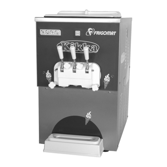
5. FUNZIONAMENTO 5.1 COMANDI 1. Coperchio vasca Impedisce alla miscela vasca di venire a contatto con polveri. 2. Pulsantiera Permette selezione programmi di lavoro 3. Portello Chiude ermeticamente cilindro durante le fasi di lavorazione. Può essere facilmente rimosso permetterne la pulizia. 4. -
Page 14: Pannello Di Controllo
5.2 PANNELLO DI CONTROLLO STOP Qualunque sia la fase operativa della macchina, premendo il tasto STOP si ferma la macchina annullando la funzione in atto. Premendo il tasto MIX si mette in funzione solo il motore agitatore; in questa funzione è attivo il controllo “Timer di sicurezza”. PRODUZIONE Premendo il tasto PRODUZIONE si inizia il ciclo di lavorazione del gelato: si accende la spia del tasto PRODUZIONE, si avvia il motore... -
Page 15: Produzione Di Gelato
5.3 PRODUZIONE DI GELATO Dopo aver provveduto all’installazione della macchina conformemente alle istruzioni del capitolo 3 ed averla accuratamente lavata e sanitizzata, secondo le istruzioni contenute nel capitolo 6, procedere nel modo seguente per iniziare la produzione di gelato: 5.3.1 Modelli con alimentazione a gravità. Verificare che l’interruttore elettrico generale sia chiuso, che il tasto STOP sia illuminato e che il rubinetto di alimentazione idrica sia aperto (solo... - Page 16 che la macchina vada in blocco a causa di insufficiente alimentazione cilindro mantecazione. Riposizionare il coperchio sulla vasca e premere il tasto PRODUZIONE per iniziare la produzione di gelato. Trascorsi alcuni minuti e raggiunto il set di consistenza macchina arresta automaticamente.
-
Page 17: Modelli Con Pompa
5.3.2 Modelli con pompa. Verificare che l’interruttore elettrico generale sia chiuso, che il tasto STOP sia illuminato e (solo per le versioni condensate ad acqua) che il rubinetto di alimentazione idrica sia aperto. Alzare il coperchio e versare la miscela in vasca (max. - Page 18 automaticamente. Il gelato ora è pronto per essere erogato. Premere il tasto START e abbassare la leva di erogazione per prelevare il gelato. Ogni 10 minuti, se non vi sono stati prelievi di gelato la macchina verifica automaticamente la consistenza del gelato e se necessario dispone l’avvio del compressore per il ripristino della condizione ottimale.
- Page 19 5.4 CONSERVAZIONE I modelli KIKKA sono dotati della pratica funzione di “conservazione” che consente all’operatore, in vista di lunghe pause di erogazione quali chiusura serale, giorno di chiusura, ecc., di commutare la macchina dalla fase produttiva a quella di stand-by. In questa fase vengono mantenuti alla temperatura idonea sia il prodotto in vasca che il gelato già...
-
Page 20: Manutenzione
FRIGOMAT consiglia di pulire accuratamente gli organi direttamente a contatto con il prodotto dopo ogni utilizzo e comunque conformemente alle norme igeniche in vigore nel paese ove la macchina è... - Page 21 Lavare accuratamente sanitizzare tutti componenti. Lubrificare utilizzando esclusivamente lubrificante alimentare FRIGOMAT (in dotazione). 6. PULIZIA DELL’AGITATORE Sfilare dal cilindro l’agitatore e rimuovere il premistoppa Rimuovere le lame raschianti e la coclea terminale. Lavare accuratamente sanitizzare tutti componenti. Per il rimontaggio procedere in ordine inverso.
- Page 22 8. PULIZIA DELLA POMPA (solo modelli con pompa) Smontaggio della pompa Spostare verso l’alto il manicotto di fissaggio. Liberare il tubo di mandata ruotandolo di 90° verso l’interno della vasca.. Svitare i due pomelli e sfilare la pompa. Rimuovere il manicotto di fissaggio e sganciare la molla di fermo per smontare la pompa nelle sue parti.
- Page 23 Rimuovere il coperchio pompa. Rimuovere dal corpo pompa la molla e la valvola di by pass Rimuovere il regolatore d’aria e disassemblarlo nelle sue parti. Rimuovere l’antischiuma e disassemblarlo nelle sue parti. Pulire con cura la membrana in gomma. Servirsi dell’attrezzo in dotazione per rimuovere tutte le guarnizioni OR;...
- Page 24 - Riattivazione della pompa Riassemblare il regolatore d’aria nelle sue parti e posizionarlo nella sede sul corpo pompa. Verificare che l’orifizio nell’estremità inferiore della valvola in gomma non sia occluso. Inserire la molla valvola e la valvola nel condotto di by pass sul corpo pompa.
-
Page 25: Manutenzione Straordinaria
6.2 MANUTENZIONE STRAORDINARIA (RIVOLTO AL PERSONALE QUALIFICATO) Queste operazioni devono essere eseguite solo ed esclusivamente da personale qualificato autorizzato. La FRIGOMAT S.r.l. declina ogni responsabilità per danni a cose o persone che possano verificarsi a causa dall’inosservanza di quanto sopra. -
Page 26: Taratura Set Di Consistenza Su Scheda Logica
6.2.1.2 TARATURA SET DI CONSISTENZA SU SCHEDA LOGICA. Questa operazione viene effettuata quando si sostituisce la scheda logica. Identificare sulla scheda logica il trimmer T2 (SET 1) e regolarlo in modo che il taglio a freccia per il cacciavite indichi le ore riportate sulla scheda di collaudo in dotazione alla macchina. -
Page 27: Istruzioni Per L'identificazione Dei Guasti
7 ISTRUZIONI PER L’IDENTIFICAZIONE DEI GUASTI 7.1 GESTIONE DEGLI ALLARMI MESSAGGIO DESCRIZIONE RIMEDI Attendere alcuni minuti e Intervenuto relè termico a STOP acceso, MIX premere il pulsante STOP protezione del motore lampeggiante e motore per resettare la macchina. agitatore (probabile agitatore fermo. -
Page 28: Ricerca Dei Guasti
7.2 RICERCA DEI GUASTI INCONVENIENTE PROBABILI CAUSE RIMEDI Anomalia elettrica o micro di Chiamare il tecnico sicurezza guasto La macchina non parte (pulsante STOP acceso senza Alimentazione non corretta Verificare le fasi. allarme attivi) Portello assemblato non Verificare portello. correttamente Interruttore generale aperto o Chiudere l’interruttore e verificare alimentazione non corretta... - Page 29 1 - ENGLISH...
-
Page 30: Important
“GUARANTEE CARD “ enclosed to the machine, which shall be duly filled up and sent back to: FRIGOMAT s.r.l., via 1° Maggio 26862 GUARDAMIGLIO (LODI) – ITALIA In the following field, please write your machine serial number in capital letters Serial number Distributor’s stamp... - Page 31 FRIGOMAT S.r.l. reserves the right to carry out all changes necessary to improve its product or manual without prior notice and to insert them in the subsequent issues.
-
Page 32: Transport, Handling And Storage
1 TRANSPORT, HANDLING AND STORAGE. 1.1 PRELIMINARY INSPECTION The machine travels at the customer’s risk. In case packing is damaged, immediately inform the carrier. Immediately inform the carrier also in case of damage to the machine, even if you open the packing a few days after the delivery. -
Page 33: Marking And Graphics
STOP position, the master switch is off and/or the multipolar plug disconnected. FRIGOMAT S.r.l. declines any liability for accidents deriving from an improper use of the machine due to the non-compliance with the above-mentioned recommendations. - Page 34 Warning! Do not touch with hands. The following plate placed on the back of air-cooled machines shows that cleaning operations on the heat exchanger shall be carried out only by means of a brush or an exhauster. Warning! High voltage inside, danger of fulguration. The following plate is placed on the electric box cover and warns the operator that in no case the cover must be removed avoiding this way the risk of...
-
Page 35: Installation
3.3 MACHINE OUTFIT No. 2 cleaning rods Feeding needle (for gravity models Soft paddle only) Beater staffing box FRIGOMAT lubricant Gasket extractor Manual of use and maintenance OR kit Declaration of conformity Fuse kit Certificate of guarantee 3.4 COMMISSIONING... - Page 36 5G4 H07RN-F (for version 400 V), 4G4 H07RN-F (for version 230/3 V) before connecting the machine to the mains. Arrange the connection of the yellow-green wire to a good earth connection. Put the machine metallic parts to earth by means of the apposite equipotent fastening screw located on the back under the frame and marked by the symbol showed on the left.
- Page 37 The ideal temperature shall range between 15° C and 35° C. The ideal humidity shall range between 30 and 60%. FRIGOMAT s.r.l. declines any liability for damages to persons and/or things due to a wrong installation and/or the non-compliance with the industrial accident prevention standards.
-
Page 38: Safety Devices
4. SAFETY DEVICE Shearing prevention system: Realized by means of microswitches and safety circuit in compliance with the European directive. It starts when the dispensing door is opened and switches the machine to STOP. Beater motor reliability of service: Realized by means of overload relays with automatic reset. -
Page 39: Operations
5. OPERATION 5.1 CONTROLS 1. Tank cover It prevents the batch inside tank from getting contact with dust. 2. Pushbutton panel It allows selecting the working programs 3. Door hermetically seals cylinder during the working cycles. easily removed cleaning purposes. 4. -
Page 40: Control Panel
5.2 CONTROL PANEL STOP Whatever working cycle is in progress, it stops the machine and cancels any function in progress. Press the MIX pushbutton to start up the beater motor; this function enables the control device “Safety timer”. PRODUCTION Press the PRODUCTION pushbutton to start up the ice-cream working cycle: the PRODUCTION pushbutton LED lights up, the beater motor starts up and after a few seconds, the compressor motor, the motor fan and the electronic module for consistency... -
Page 41: Ice-Cream Production
5.3 ICE-CREAM PRODUCTION After the machine has been installed according to the instructions reported in chapter 3 and carefully cleaned and sanitized according to the instructions reported in charter 6, proceed to start up the ice- cream production as follows: 5.3.1 Models with gravity feeding. - Page 42 After a few minutes the consistency set is reached and the machine automatically stops. The ice-cream is ready to be dispensed. Press the START pushbutton and lower the dispensing lever to draw the ice-cream out. Every 10 minutes, in case no ice-cream delivery takes place, the machine automatically check the ice-cream consistency and in case of necessity it starts the compressor up to restore the ideal...
-
Page 43: Models With Pump
5.3.2 Models with pump. Check that the master switch is closed, the STOP pushbutton is ON and (for water-condensed versions only) the water tap is open. Lift the cover and pour the mixture into the tank (max. 6 litres) at conservation temperature. To select the desired volume increase, make use of the air damper placed on the pump casing as follows: Screw down the notched knob until it... - Page 44 Every 10 minutes, in case no ice-cream delivery takes place, the machine automatically check for the ice-cream consistency and in case of necessity it starts the compressor up to restore the ideal condition. This way the ice-cream is always ready to be delivered. After a long stop, it is advisable to press START and wait for a few seconds before lowering the dispensing lever;...
- Page 45 5.4 CONSERVATION KIKKA models are provided with the convenient “conservation” function, which allows the operator to switch the machine from production to stand-by mode in case of long pauses in ice-cream delivery due to evening closing, closing day etc. During this phase, the machine keeps the product in the tank and the end-ice-cream in the cylinder at suitable temperatures.
-
Page 46: Maintenance
In case of troubles, make sure that they are not caused by a lack of servicing. On the contrary, ask for the intervention of a FRIGOMAT customer service. In case it is necessary to replace a piece, always ask a distributor or an authorized retailer for ORIGINAL spare parts. - Page 47 Remove the O-rings by means of the apposite tool provided as standard. Thoroughly wash and sanitize all components. Lubricate the O-rings with lubricant for food industry FRIGOMAT only (included in standard equipment). 6. BEATER CLEANING Take the beater out of the cylinder and remove the stuffing box.
- Page 48 8. PUMP CLEANING (for models with pump only) Pump disassembly Move the connecting sleeve upwards. Release the delivery pipe by 90° rotating it towards the tank interior. Unscrew the two knobs and take the pump out. Remove the anchoring sleeve and release the retaining spring to disassemble the pump.
- Page 49 Remove the pump cover. Take the spring and the by-pass valve out of the pump casing. Remove the air damper and disassemble it. Remove the anti-foaming device and disassemble it. Accurately clean the rubber diaphragm. Make use of the tool included in the standard equipment to remove the O-rings.
- Page 50 - Restarting the pump Reassemble the air damper and place it in its seat in the pump casing. Check that the orifice in the rubber valve lower end is not obstructed. Insert the valve spring and the valve into the by- pass duct on the pump casing.
-
Page 51: Extraordinary Maintenance
6.3 EXTRAORDINARY MAINTENANCE (ADDRESSED TO QUALIFIED PERSONNEL) These operations shall be carried out by qualified and authorized personnel only. FRIGOMAT S.r.l. declines any liability for damages to things or persons deriving from the non-observance of the above-mentioned prescription. 6.2.1 ELECTRIC INSTALLATION 6.2.1.1 CONSISTENCY SET ADJUSTMENT ON “CT”... -
Page 52: Consistency Set Adjustment On Logic Card
6.2.1.2 CONSISTENCY SET ADJUSTMENT ON LOGIC CARD. This operation must be carried when replacing the logic card. On the logic card, locate the trimmer T2 (SET 1) and adjust it so that the arrow cut for the screwdriver indicates the hours reported in the test sheet enclosed to the machine. Then check the correct adjustment of the consistency set on the “CT”... -
Page 53: Trouble-Shooting
7 TROUBLE-SHOOTING 7.1 ALARMS MANAGEMENT MESSAGGIO DESCRIZIONE RIMEDI Wait for a few seconds and The overload relay has press the STOP pushbutton STOP on, MIX blinking, tripped to protect the beater to reset the machine. If the beater motor off. motor (possible overheating) problem is frequent, call for a technician. -
Page 54: Troubleshooting
7.2 TROUBLESHOOTING TROUBLE POSSIBLE CAUSES REMEDIES Electric trouble or failed safety Call for the technician The machine does not start up microswitch (STOP pushbutton ON without Incorrect power supply Check the phases. active alarms) Wrong door assembly Check the door. Master switch OFF or incorrect Close the switch and check the power supply... - Page 55 1 - FRANÇAIS...
- Page 56 La machine est sous garantie aux conditions illustrées sur la fiche “CARTOLINA DI GARANZIA “ jointe qui doit être dûment remplie et renvoyée à : FRIGOMAT s.r.l., via 1° Maggio 26862 GUARDAMIGLIO (LODI) – ITALIE Veuillez bien indiquer dans le champ ci-dessous le numéro d’immatriculation de votre machine Numéro d’immatriculation...
- Page 57 Dans les pages qui suivent figurent toutes les indications permettant d’effectuer correctement les opérations d’installation, de fonctionnement, de réglage et d’entretien courant. FRIGOMAT S.r.l. se réserve le droit d’apporter toutes les modifications qu’elle jugera nécessaires à l’amélioration de son produit ou de son manuel technique, en insérant les variantes dans les éditions successives.
-
Page 58: Transport, Manutention Et Stockage
1 TRANSPORT, MANUTENTION ET STOCKAGE. 1.1 INSPECTION PRELIMINAIRE La machine voyage aux risques et périls de l’acquéreur; si vous remarquez que l’emballage est abîmé, émettez immédiatement une réserve auprès du transporteur. Si vous remarquez que la machine est abîmée, émettez également une réserve auprès du transporteur tout de suite après le déballage, même s’il est effectué... -
Page 59: Marquage Et Signes Graphiques
STOP, que l’interrupteur général soit bien coupé et/ou que la fiche de courant multipolaire soit bien débranchée. FRIGOMAT S.r.l. décline toute responsabilité en cas d’éventuel accident qui se produirait suite à la non-application des points susdits durant l’utilisation de ses machines. - Page 60 Attention! Ne pas toucher avec les mains. Cette plaquette appliquée sur le panneau postérieur des machines avec système de refroidissement à air indique que les opérations de nettoyage sur l’échangeur de chaleur doivent être effectuées uniquement à l’aide d’un pinceau ou d’un aspirateur. Attention! Haute tension...
-
Page 61: Installation
(seulement pour modèles à Presse-garniture pour agitateur gravité) Extracteur de joints Lubrifiant FRIGOMAT Kit OR Manuel d’utilisation et d' entretien Kit fusibles Déclaration de conformité Certificat de garantie 3.4 MISE EN SERVICE Amener la machine sur le lieu d’utilisation et vérifier les prescriptions concernant son installation : alimentation électrique;... - Page 62 Brancher le câble d’alimentation de la machine à une fiche conforme aux normes : le câble doit être bien tendu, sans enroulements ni superpositions, il ne doit pas être exposé aux risques de chocs ou d’altérations; il ne doit pas se trouver à proximité de liquides ou d’eau ni de sources de chaleur;...
-
Page 63: Nettoyage
La température optimale doit être comprise entre 15° C et 35° C. L' humidité optimale doit être comprise entre 30 et 60%. FRIGOMAT S.r.l. décline toute responsabilité en cas d’éventuels dommages aux personnes et/ou aux choses qui se produiraient suite à une installation non correcte et/ou au non-respect des normes de prévention des accidents du travail. -
Page 64: Dispositifs De Securite
4. DISPOSITIFS DE SECURITE Dispositif de sécurité anti-cisaillement: Réalisé au moyen de microinterrupteurs et circuit de sécurité conformes à la directive européenne; il intervient quand on enlève la porte distributrice en commutant la machine sur STOP. Dispositif de sécurité fonctionnement moteur agitateur: Réalisé au moyen de relais thermiques avec rétablissement automatique;... -
Page 65: Fonctionnement
5. FONCTIONNEMENT 5.1 COMMANDES 1. Couvercle cuve Il empêche au mélange dans la cuve d' entrer au contact des poussières. 2. Clavier Il permet de sélectionner les programmes de travail 3. Porte Elle ferme hermétiquement le cylindre pendant les phases de travail. -
Page 66: Tableau De Commandes
5.2 TABLEAU DE COMMANDES STOP Quelle que soit la phase opérationnelle de la machine, en appuyant sur la touche STOP on arrête la machine en annulant la fonction en cours. En appuyant sur la touche MIX on met en marche seulement le moteur de l' agitateur;... -
Page 67: Production De Glace
5.3 PRODUCTION DE GLACE Après avoir effectué l' installation de la machine conformément aux instructions du chapitre 3 et l' avoir soigneusement lavée et assainie, selon les instructions contenues dans le chapitre 6, procéder manière suivante pour commencer production de glace: 5.3.1 Modèles avec alimentation à... - Page 68 Les mélanges particulièrement denses demandent une régulation du curseur sur des positions voisines aux valeurs maximums (4,5 ou 6); en cas contraire on risque que la machine se bloque à cause d' une alimentation insuffisante au cylindre de malaxage. Repositionner le couvercle sur la cuve et appuyer sur la touche PRODUCTION pour commencer la production de glace.
-
Page 69: Modèles Avec Pompe
5.3.2 Modèles avec pompe. Vérifier que l' interrupteur électrique général soit fermé, que la touche STOP soit allumée et (seulement pour les versions condensées à l' eau), que le robinet d' alimentation hydrique soit ouvert. Soulever le couvercle et verser le mélange dans la cuve (max. - Page 70 Après quelques minutes et une fois atteint le niveau optimal de consistance la machine s' arrête automatiquement. La glace est prête pour être débitée. Appuyer sur la touche START et baisser le levier de débit pour prélever la glace. Toutes les 10 minutes, si la glace n' a pas été prélevée, la machine vérifie automatiquement la consistance de la glace et si nécessaire elle démarre le compresseur pour la restauration de...
-
Page 71: Conservation
5.4 CONSERVATION Les modèles KIKKA sont dotés de la fonction pratique de "conservation" qui permet à l' opérateur, en vue de longues pauses de débit telles que fermeture du soir, jour de fermeture, etc., de commuter la machine de la phase productive à celle de stand-by. -
Page 72: Entretien
Si oui, demander l’intervention d’un centre d’assistance FRIGOMAT. En cas de remplacement de pièces, demander exclusivement des pièces détachées originales FRIGOMAT à un concessionnaire ou à un revendeur autorisé. Il est conseillé de faire effectuer un contrôle sur la machine par un Centre d’Assistance tous les 6/8 mois. -
Page 73: Nettoyage De La Porte
OR. Laver soigneusement assainir tous composants. Graisser utilisant exclusivement le lubrifiant alimentaire FRIGOMAT (fourni). 6. NETTOYAGE DE L' AGITATEUR Extraire du cylindre l' agitateur et enlever le presse- garniture Enlever les lames de raclage et la vis terminale. Laver soigneusement... - Page 74 8. NETTOYAGE DE LA POMPE (seulement pour les modèles à pompe) Démontage de la pompe Déplacer vers le haut le manchon de fixation Dégager le tuyau de refoulement en le tournant de 90° vers l' intérieur de la cuve. Dévisser les deux poignées et extraire la pompe. Enlever le manchon de fixation et décrocher le ressort d' arrêt pour démonter la pompe de toutes pièces.
- Page 75 Enlever le couvercle de la pompe. Enlever du corps de la pompe le ressort et la soupape de by pass Enlever le régulateur d' air et le démonter de toutes pièces. Enlever le démousseur et le démonter de toutes pièces. Nettoyer soigneusement la membrane en caoutchouc.
- Page 76 - Remise en marche de la pompe Réassembler le régulateur d' air et le positionner dans son siège sur le corps de la pompe. Vérifier que l' orifice à l' extrémité inférieure de la soupape en caoutchouc ne soit pas occlus. Insérer le ressort de soupape et la soupape dans la conduite de by pass sur le corps de la pompe.
-
Page 77: Entretien Extraordinaire
6.2 ENTRETIEN EXTRAORDINAIRE (ADRESSE A UN PERSONNEL QUALIFIE) Ces opérations doivent être exécutées seulement et exclusivement par un personnel qualifié autorisé. FRIGOMAT S.r.l. décline toute responsabilité pour les dommages provoqués aux choses ou personnes dérivant de l' inobservance de ce qui a été cité plus haut. -
Page 78: Calibrage Set De Consistance Sur Carte Logique
6.2.1.2 CALIBRAGE SET DE CONSISTANCE SUR CARTE LOGIQUE. On effectue cette opération quand on remplace la carte logique. Identifier sur la carte logique le trimmer T2 (SET 1) et le régler de sorte que l’encoche en flèche pour le tournevis indique les heures reportées sur la fiche d' essai livrée avec la machine. -
Page 79: Instructions Pour L'identification Des Pannes
7 INSTRUCTIONS POUR L’IDENTIFICATION DES PANNES 7.1 GESTION DES ALARME MESSAGGIO DESCRIZIONE RIMEDI Attendre quelques minutes Le relais thermique de et appuyer sur STOP pour STOP allumé, MIX clignotant protection du moteur remettre la machine à l' état et moteur agitateur arrêté. agitateur est intervenu initial. -
Page 80: Recherche Des Pannes
7.2 RECHERCHE DES PANNES INCONVENIENT CAUSES PROBABLES REMEDES Anomalie électrique ou micro de Appeler le technicien sécurité en panne La machine ne démarre pas (touche STOP allumée sans Alimentation non correcte Vérifier les phases. alarmes actives) Porte assemblée de façon non Vérifier la porte. - Page 81 1 - DEUTSCH...
- Page 82 WICHTIG Wir raten Ihnen, bevor Sie die Ihre FRIGOMAT Maschine benutzen, aufmerksam und vollständig dieses Handbuch zu lesen. In Ihrem Interesse achten Sie besonders auf die Hinweise, welche mit diesen Zeichen versehen sind: Wenn Sie diesen Hinweis nicht beachten sollten, bringen Sie Ihre eigene Gesundheit in Gefahr u/o den Betrieb der Maschine.
- Page 83 Wir bedanken uns bei Ihnen und beglückwünsche sie, dass Sie eine FRIGOMAT Maschine erworben haben. Das vorliegende Handbuch wird mit der Maschine mitgeliefert und ist als wichtiges Bestandteil anzusehen. Es muß dem Benutzer der Maschine übergeben werden. Bevor Sie jeglichen Arbeitsgang an der Maschine durchführen raten wir strikt, die enthaltenen Hinweise genau zu studieren, da nur durch ein genaues Lesen die höchste Maschinenleistung garantiert...
-
Page 84: Transport, Maschinenversetzung Und Lagerung
1 TRANSPORT, MASCHINENVERSETZUNG UND LAGERUNG 1.1 EINLEITENDE KONTROLLEN Die Maschine wird auf Risiko und Gefahr des Auftraggebers transportiert; wenn Sie Beschädigungen an der Verpackung bemerken sollten, weisen Sie bitte sofort den Spediteur darauf hin. Informieren Sie den Spediteur ebenfalls, auch wenn Sie erst nach einigen Tagen der Auslieferung die Verpackung öffnen und Beschädigungen an der Maschine bemerken sollten. -
Page 85: Markierungen Und Zeichen
Maschine auf STOP geschaltet, der Hauptschalter abgeschaltet u/o der Mehrpolnetzstecker gezogen ist. Die Firma FRIGOMAT S.r.l. übernimmt keine Haftung für Unfälle, die sich während des Gebrauchs der Maschinen ereignen können, die auf die Nichtbeachtung der oben genannten Punkte zurückzuführen ist. - Page 86 Achtung! Nicht mit den Händen berühren. Das bei Maschinen mit Luftkühlung am hinteren Paneel angebrachte Schild zeigt an, dass die Reinigung des Wärmetauschers nur mit einem Pinsel oder mit einem Sauggerät durchgeführt werden sollte. Achtung! Hochspannung im Inneren vorhanden; es besteht die Gefahr eines elektrischen Schlages.
-
Page 87: Installation
Angaben auf der Packung entsprechen. 3.3 MASCHINENAUSSTATTUNG 2 Flaschenbürsten Versorgungsstift (nur für weiche Schaufel Produktfallmodelle) Rührwerkstopfdichtung Schmiermittel FRIGOMAT Ausziehwerkzeug für Dichtungen Gebrauchshandbuch Kit O-Ringe Wartungshandbuch Kit-Sicherungen Konformitätsbescheinigung Garantiezertifikat 3.4 INBETRIEBNAHME Die Maschine an den Gebrauchsort transportieren und die Anforderungen zur Installation prüfen:... - Page 88 anbringen, der auch eine Sicherung besitzt, um den Stecker bei geöffnetem Netz einschalten und ausschalten zu können. Das Netzkabel an einen geprüften Netzstecker anschließen: das Kabel muß gut ausgelegt sein und man muß Knoten oder Überkreuzungen als auch Beschädigungen vermeiden; das Kabel darf nicht in der Nähe von Flüssigkeiten oder Wasser und heißen Wärmequellen ausgelegt werden;...
- Page 89 Die optimale Temperatur soll zwischen 15° C und 35° C liegen. Die optimale Feuchtigkeit sollte zwischen 30 und 60% liegen. Die Firma FRIGOMAT s.r.l. übernimmt keine Haftung für eventuelle Schäden an Personen u/o Sachen, die auf eine falsche Installation u/o durch ein Nichtbeachten der Normen zur Vorbeugung für Unfälle am Arbeitsplatz zurückzuführen sind.
-
Page 90: Sicherheitsvorrichtungen
4. SICHERHEITSVORRICHTUNGEN Sicherheit Schneidegefahr: Mittels eines Mikroschalters mit Auslöseöffnung gemäß der europäischen Vorschriften; der Mikroschalter schaltet bei Abnahme der Ausgabeöffnung Maschine in STOP-Stellung. Betriebssicherheit Rührwerkmotoren: Mittels Thermorelais mit automatischer Freischaltung; es schützt den Rührwerkmotoren vor Überlastungen, indem der Betrieb blockiert wird, gleichzeitig leuchten die STOP-Taste auf und es blinkt die MIX Taste. -
Page 91: Betrieb
5. BETRIEB 5.1 EINZELTEILE 1. Behälterdeckel Verhindert, Behälter befindliche Mischung mit Staub oder Schmutz in Berührung kommt. 2. Tastenfeld Erlaubt die Einstellung der Arbeitsprogramme. 3. Klappenöffnung Verschließt Rührzylinderkammer während der Verarbeitung hermetisch. Kann ganz einfach für eine Reinigung abgenommen werden. 4. -
Page 92: Kontrolltafel
5.2 KONTROLLTAFEL STOP Egal welche Verarbeitungsphase die Maschine durchläuft wird beim Drücken der STOP-Taste die Maschine gestoppt und die laufende Funktion gestrichen. Durch Drücken der MIX-Taste wird nur der Rührwerkmotor gestartet; während dieser Funktion ist die Kontrolle “Sicherheits-Timer” aktiv. PRODUKTION Durch Drücken Taste... -
Page 93: Eisproduktion
5.3 EISPRODUKTION Nachdem man die Maschine nach den im Kapitel 3 angegebenen Angaben installiert, gründlich gewaschen und eine Sanitisation, wie im Kapitel 6 beschrieben durchgeführt hat, kann man mit der Eisproduktion beginnen: 5.3.1 Modelle mit Produktfallversorgung Prüfen, dass elektrische Hauptschalter geschlossen ist, dass die STOP-Taste leuchtet und der Wasserversorgungshahn offen ist (nur für die Kondenswassermodelle). - Page 94 Maschine blockiert, Grund nicht ausreichender Versorgung des Rührzylinders. Den Deckel auf den Behälter setzen und die PRODUKTIONS-Taste Eisproduktion drücken. Nach Ablauf von einigen Minuten und bei Erreichen Konsistenz-Set, bleibt Maschine automatisch stehen. Das Eis ist jetzt zur Ausgabe fertig. START-Taste drücken Ausgabehebel herunterschalten, um das Eis zu entnehmen.
-
Page 95: Modelle Mit Pumpe
5.3.2 Modelle mit Pumpe Prüfen, dass elektrische Hauptschalter geschlossen ist, dass die STOP-Taste leuchtet und der Wasserversorgungshahn offen ist (nur für die Kondenswassermodelle). Die Mischung bei Konservierungstemperatur in den Behälter gießen (max. 6 Liter). Um eine gewünschte Volumenerhöhung zu erzielen, den Luftregler am Pumpenkörper wie folgt betätigen: den zackigen Griff bis zur Feststellung schrauben... - Page 96 START-Taste drücken Ausgabehebel herunterschalten, um das Eis zu entnehmen. Alle Minuten überprüft Maschine automatisch Eiskonsistenz, wenn keine Ausgaben erfolgt sind; wenn notwendig, wird der Kompressor eingeschaltet, optimale Konditionen wiederherzustellen. Dadurch bleibt das Eis immer für die Ausgabe fertig. Wenn man das Eis nach einer längeren Pause Ausgeben möchte, empfehlen wir START zu drücken und einige Sekunden abzuwarten, bevor man den Ausgabehebel herunterschaltet;...
- Page 97 5.4 KONSERVIERUNG KIKKA-Modelle sind praktischen Konservierungs-Funktion ausgestattet, die Bediener Möglichkeit liefert, langen Ausgabepausen, Ladenschluss, Feiertagspausen, etc., Maschine Produktionsphase Stand-by-Phase umzuschalten. In dieser Phase werden sowohl das Produkt im Behälter als auch das fertige Eis im Zylinder bei der richtigen Temperatur gehalten; außerdem führt die Maschine Eiskonsistenzkontrollen längeren...
-
Page 98: Wartung
Maschine bemerken sollte, muß man sich vergewissern, dass diese nicht durch fehlende Normalwartung hervorgerufen wurden. Im entgegengesetzten Fall muß der Kundendienst der Firma FRIGOMAT verständigt werden. Im Austauschfall von Teilen nur Originalteile der Firma Firgomat beim Konzessionär oder autorisiertem Wiederverkäufer anfragen. - Page 99 Hebel herunterstellen, um die Lösung abzulassen. 4. STOP drücken und in den Behälter einige Liter lauwarmes Wasser einfüllen. MIX-Taste drücken und den Hebel herunterstellen; diesen Vorgang, solange wiederholen, bis sauberes Wasser aus der Klappenöffnung kommt. 5. KLAPPENÖFFNUNGSREINIGUNG Nachdem gesamte Waschwasser abgelassen hat, die STOP-Taste drücken;...
- Page 100 8. PUMPENREINIGUNG (nur Pumpenmodellen) Pumpe auseinandernehmen Die Befestigungsmuffe nach oben verstellen Das Zulaufrohr befreien, indem man es um 90° in Richtung Behälterinnenseite dreht. Beide Kugelgriffe abschrauben und die Pumpe herausziehen. Befestigungsmuffe entfernen Feststellfeder abhaken, um die Pumpe in ihre Einzelteile zerlegen zu können. Den vorderseitigen Metallteller mit entsprechender Ventilfeder und Ventil entfernen DEUTSCH - 20...
- Page 101 Den Pumpendeckel entfernen. Vom Pumpenkörper die Feder und das By pass-Ventil entfernen Den Luftregler entfernen und in seine Einzelteile zerlegen. Antischaumvorrichtung entfernen ihre Einzelteile zerlegen. Mit großer Sorgfalt die Gummimembrane reinigen. beigelegten Werkzeug alle Ringdichtungen entfernen; alle abgebauten Teile in eine Schüssel lauwarmem Wasser und...
- Page 102 - Wiederinbetriebnahme der Pumpe Luftregler seine Teile wieder zusammensetzen und ihn in seinen Sitz auf dem Pumpenkörper setzen. Prüfen, dass die Öffnung am unteren Ventilende aus Gummi nicht verstopft ist. Ventilfeder und Ventil in den Leitkanal des by pass auf dem Pumpenkörper einfügen. Den Plastikdeckel komplett mit O-Ringen auf den Pumpenkörper montieren.
-
Page 103: Elektrische Anlage
6.2 AUSSERGEWÖHNLICHE WARTUNG (FÜR QUALIFIZIERTES PERSONAL) Diese Arbeitsgänge dürfen ausschließlich von autorisiertem Fachpersonal durchgeführt werden. Die Firma FRIGOMAT S.r.l. übernimmt keine Haftung für Schäden an Sachen oder Personen, die auf ein Nichtbeachten dieser Angaben zurückzuführen sind. 6.2.1 ELEKTRISCHE ANLAGE 6.2.1.1 TARATURA SET DI CONSISTENZA SU SCHEDA “TA”... -
Page 104: Einstellung Konsistenz-Set Auf Logikkarte
6.2.1.2 EINSTELLUNG KONSISTENZ-SET AUF LOGIKKARTE. Dieser Arbeitsgang wird durchgeführt, wenn die Logikkarte ausgetauscht wird. Auf der Logikkarte den Trimmer T2 (SET 1) ausfindig machen und diesen so einstellen, dass die Pfeilkerbe für den Schraubenzieher die angezeigten Stunden angibt, die auf der beigelegten Prüfkarte der Maschine angegeben sind. -
Page 105: Hinweise Zur Fehlersuchei
7 HINWEISE ZUR FEHLERSUCHE 7.1 ALARMERKENNUNG MESSAGGIO DESCRIZIONE RIMEDI Einige Minuten warten und dann die Taste STOP drücken, AusgelöstesThermorelais, STOP Zugang, MIX blinkt um ein reset der Maschine um den Rührwerkmotor zu und der Rührwerkmotor steht durchzuführen. Wenn das schützen (mögliche still. -
Page 106: Fehlersuche
7.2 FEHLERSUCHE FEHLER MÖGLICHE URSACHE LÖSUNG Elektrische Störung oder Techniker rufen Sicherheitsmikroschalter defekt Die Maschine startet nicht (Taste STOP leuchtet ohne Nicht korrekte Versorgung Phasenkabel prüfen Aktivalarm) Klappenöffnung nicht korrekt Klappenöffnung prüfen zusammengebaut Hauptschalter offen oder nicht Hauptschalter abschalten und die korrekte Versorgung Phasenkabel überprüfen Maschine startet nicht... - Page 107 1 - ESPAÑOL...
- Page 108 La máquina está cubierta por garantía según las condiciones ilustradas en la “CARTA DE GARANT A “ en dotación que deberá ser cumplimentada y devuelta a: FRIGOMAT s.r.l., via 1° Maggio 26862 GUARDAMIGLIO (LODI) – ITALIA Por favor escriban en el campo de abajo el número de matrícula de su máquina Número matrícula...
- Page 109 Reciba nuestras felicitaciones por haber adquirido una máquina FRIGOMAT. El siguiente manual, suministrado en dotación con la máquina, ha de considerarse parte integrante y esencial de la misma y tendrá que ser entregado al usuario final. Antes de efectuar cualquier operación se recomienda estudiar atentamente las instrucciones presentes en él, ya que sólo una...
-
Page 110: Transporte, Desplazamiento Y Almacenaje
1 TRANSPORTE, DESPLAZAMIENTO Y ALMACENAJE. 1.1 INSPECCIÓN PRELIMINAR La máquina viaja a riesgo y peligro del comitente, si se notan daños en el embalaje, hay que poner objeción inmediatamente al transportista. Ponga igualmente objeción al transportista enseguida después de la apertura del embalaje, aunque esto ocurra algún día después de la entrega, si se hallan daños en la máquina. -
Page 111: Marca Y Señales Gráficas
STOP, el interruptor general abierto y/o el enchufe multipolar de corriente desconectado. FRIGOMAT S.r.l. declina cualquier responsabilidad relativamente a incidentes que puedan ocurrir durante el uso de las propias máquinas causados por la inobservancia de lo indicado arriba. - Page 112 Atención! No tocar con las manos. La siguiente placa aplicada en el panel posterior de las máquinas con refrigeración de aire indica que las operaciones de limpieza del cambiador de calor tiene que efectuarse solamente con un pincel o con una aspiradora.
-
Page 113: Instalación
N° 2 Escobillas limpiabotellas Aguja para alimentación (sólo Pala blanda modelos de gravedad) Prensaestopas para agitador Lubrificante FRIGOMAT Extractor guarniciones Manual de uso y mantenimiento Kit juntas tóricas OR Declaración de conformidad Kit fusibles Certificado de garantía 3.4 PUESTA EN FUNCIÓN Llevar la máquina en el lugar de utilización verificando lo requerido para su instalación:... - Page 114 expuesto a eventuales golpes o modificaciones; no tiene que estar cerca de líquidos o agua y fuentes de calor; en ningún caso tiene que estar dañado, por el contrario hacerlo sustituir por personal cualificado antes de la conexión de la máquina a la red con otro de sección y tipo 5G4 H07RN-F (para versión 400 V), 4G4 H07RN-F (para versión 230/30 V).
- Page 115 La temperatura ideal tiene que estar incluida entre 15° C y 35° C. La humedad ideal tiene que estar incluida entre 30 y 60%. FRIGOMAT s.r.l. declina toda responsabilidad para eventuales daños a personas y/o cosas causados por una instalación errónea y/o de la inobservancia de las normas para la prevención de los accidentes laborales.
-
Page 116: Dispositivos De Seguridad
4. DISPOSITIVOS DE SEGURIDAD Seguridad anticizallado: Realizada mediante microinterruptor y circuito de seguridad conformes a la directiva europea; interviene cuando se quita la tapa suministrador conmutando la máquina en STOP. Seguridad funcionamiento motor agitador: Realizada mediante relés térmicos con reposición automática; protegen de sobrecargas el motor agitador bloqueando el funcionamiento de la máquina iluminando el pulsador STOP e iluminando de modo intermitente la tecla MIX. -
Page 117: Funcionamiento
5. FUNCIONAMIENTO 5.1 MANDOS 1. Tapa cuba Impide que la mezcla en la cuba entre en contacto con polvos. 2. Panel de mandos Permite la selección de los programas de trabajo 3. Tapa Cierra herméticamente cilindro durante las fases de elaboración. -
Page 118: Panel De Control
5.2 PANEL DE CONTROL STOP Cualquier sea la fase operativa de la máquina, presionando la tecla STOP la máquina se para anulando la función en curso. Presionando la tecla MIX se pone en función sólo el motor agitador; en esta función está activo el control “Temporizador de seguridad”. PRODUCCIÓN Presionando la tecla PRODUCCIÓN inicia el ciclo de elaboración del helado: se enciende el testigo de la tecla PRODUCCIÓN, se pone en... -
Page 119: Produccion De Helado
5.3 PRODUCCIÓN DE HELADO Tras haber efectuado la instalación de la máquina conformemente a las instrucciones del capítulo 3 y haberla lavada y desinfectada esmeradamente, según las instrucciones contenidas en el capítulo 6, proceder siguiente modo para iniciar la producción de helado: 5.3.1 Modelos con alimentación por gravedad. - Page 120 riesgo que la máquina se bloquee a causa de insuficiente alimentación al cilindro batidor. Volver a posicionar la tapa en la cuba y presionar la tecla PRODUCCIÓN para iniciar la producción de helado. Pasados algunos minutos y alcanzado el punto consistencia, máquina para...
-
Page 121: Modelos Con Bomba
5.3.2 Modelos con bomba. Verificar que el interruptor eléctrico general esté cerrado, que la tecla STOP esté iluminada y (sólo para las versiones condensadas con agua) que el grifo de alimentación hídrica esté abierto. Alzar la tapa y verter la mezcla en la cuba (máx. 6 litros) a temperatura de conservación. - Page 122 automáticamente. El helado ahora está listo para ser suministrado. Presionar la tecla START y bajar la palanca de suministro para retirar el helado. Cada 10 minutos, si no hay habido retiros de helado, la máquina verifica automáticamente la consistencia del helado y si es necesario dispone la puesta en marcha del compresor para la reposición de la condición ideal.
- Page 123 5.4 CONSERVACIÓN Los modelos KIKKA están dotados de la práctica función de “conservación” que consiente al operador, en vista de largas pausas de suministro como cierre nocturno, día de cierre, etc., conmutar la máquina de la fase productiva a la de espera. En esta fase el producto en la cuba y el helado ya listo en el cilindro se mantienen a la temperatura;...
-
Page 124: Mantenimiento
En caso se hallaran anomalías en el funcionamiento de la máquina, asegurarse de que no dependan de la falta de mantenimiento ordinario. En caso contrario pedir la intervención de un centro asistencia FRIGOMAT. En caso de sustitución de piezas, pedir exclusivamente recambios originales FRIGOMAT a un concesionario o a un revendedor autorizado. -
Page 125: Limpieza De La Tapa
Lavar esmeradamente y desinfectar todos los componentes. Lubrificar juntas tóricas utilizando exclusivamente el lubrificante alimenticio FRIGOMAT (suministrado). 6. LIMPIEZA DEL AGITADOR Extraer del cilindro el agitador y quitar el prensaestopas Quitar las cuchillas rascadoras y el tornillo sin fin terminal. - Page 126 8. LIMPIEZA DE LA BOMBA (sólo modelos con bomba) Desmontaje de la bomba Desplazar hacia arriba el manguito de fijación Liberar el tubo de descarga girándolo de 90° hacia el interior de la cuba. Desenroscar los dos pomos y extraer la bomba. Quitar el manguito de fijación y desenganchar el muelle de tope para desmontar la bomba en sus partes.
- Page 127 Quitar la tapa de la bomba. Quitar del cuerpo bomba el muelle y la válvula de by pass Quitar el regulador de aire y desensamblarlo en sus partes. Quitar el antiespuma y desensamblarlo en sus partes. Limpiar con esmero la membrana de goma. Utilizar la herramienta en dotación para quitar todas las juntas tóricas (OR);...
- Page 128 - Reactivación de la bomba Volver a montar el regulador de aire en todas sus partes y posicionarlo en la sede en el cuerpo bomba. Verificar que el orificio en la extremidad inferior de la válvula de goma no esté atascado. Introducir el muelle válvula y la válvula en el conducto de by pass en el cuerpo bomba.
-
Page 129: Mantenimiento Extraordinario
6.2 MANTENIMIENTO EXTRAORDINARIO (DIRIGIDO AL PERSONAL CALIFICADO) Estas operaciones han de ser efectuadas solamente y exclusivamente por personal cualificado autorizado. FRIGOMAT S.r.l. declina cualquier responsabilidad por daños a cosas o personas que puedan ocurrir a causa de la inobservancia de lo indicado arriba. -
Page 130: Calibrado Punto De Consistencia En La Tarjeta Lógica
6.2.1.2 CALIBRADO PUNTO DE CONSISTENCIA EN LA TARJETA LÓGICA. Esta operación se efectúa cuando se sustituye la tarjeta lógica. Identificar en la tarjeta lógica el trimmer T2 (PUNTO 1) y regularlo de modo que el corte de flecha para el destornillador indique las horas indicadas en la tarjeta de prueba en dotación a la máquina. -
Page 131: Instrucciones Para La Identificación De Las Averías
7 INSTRUCCIONES PARA LA IDENTIFICACIÓN DE LAS AVERÍAS 7.1 GESTIÓN DE LAS ALARMAS MESSAGGIO DESCRIZIONE RIMEDI Esperar algunos minutos y Relé térmico intervenido STOP encendido, MIX presionar el pulsador STOP para proteger el motor intermitente y motor agitador para poner a cero la agitador (probable parado. -
Page 132: Búsqueda De Las Averías
7.2 BUSQUEDA DE LAS AVERÍAS INCONVENIENTE PROBABLES CAUSAS REMEDIOS Anomalía eléctrica o microinterruptor de seguridad Llamar al técnico La máquina no se pone en marcha (pulsador STOP encendido sin averiado alarmas activas) Alimentación no correcta Verificar las fases. Tapa no correctamente montada Verificar tapa. - Page 133 Tensione Potenza Dimensioni Peso netto Capacità Produzione MODELLO alimentazione installata Condensaz. (mm) (Kg) (lt) (kg/h) (kW) Installed Size Net weight Suppy voltage Capacity Production MODEL power Cooling (mm) (Kg) (lt) (kg/h) (kw) Tension Puissance Dimmension Poids net Capacité Production MODELE d’alimentation installé...
- Page 134 8.2 Schema circuito frigorifero KIKKA 1 / KIKKA 1 Refrigerant circuit diagram / Schéma du circuit frigorifique KIKKA 1 / Kühlnetzplan KIKKA 1 / Esquema circuito frigorifico KIKKA 1 APPENDICI - 2...
- Page 135 Schema circuito frigorifero KIKKA 3-330 / KIKKA 3-330 Refrigerant circuit diagram / Schéma du circuit frigorifique KIKKA 3-330 / Kühlnetzplan KIKKA 3-330/ Esquema circuito frigorifico KIKKA 3-330 3 - APPENDICI...
- Page 136 In case it is necessary to replace a component, always ask a distributor or an authorized retailer for ORIGINAL spare parts. FRIGOMAT declines any liability for damages to people and/or things due to employment of non-original spare parts.
- Page 137 KIKKA 1/s05 - KIKKA 1P/s06 Tav.1/9 5 - APPENDICI...
- Page 138 KIKKA 1/s05 - KIKKA 1P/s06 Tav.1/9 BESCHREIBU COD. DESCRIZIONE DESCRIPTION DESCRIPTION DESCRIPTION Electrode de B12.163 Elettrodo livello Niveau electrode Niveau-Elektrode Electrodo de nivel niveau Niveau- P02.215 Prolunga livello Niveau extension Rallonge niveau Alargadera nivel Verlängerung Gruppo kompl. Zylinder – Grupo Insulation unit Groupe isolant à...
- Page 139 KIKKA 1/s05 - KIKKA 1P/s06 Tav.2/9 7 - APPENDICI...
- Page 140 KIKKA 1/s05 - KIKKA 1P/s06 Tav.2/9 COD. DESCRIZIONE DESCRIPTION DESCRIPTION BESCHREIBUNG DESCRIPTION E05.38071 Sonda temperatura Temperature probe Sonde température Temperatursonde Sonda temperatura T01.006 Capillare Capillary tube Capillaire Kapillares Capilar A07.089 Filtro Filter Filtre Filter Filtro A02.155 Bobina elettrovalvola Solenoid valve coil Bobine électrovanne Spule Elektroventil Bobina electrov lvula...
- Page 141 KIKKA 1/s05 - KIKKA 1P/s06 Tav.3/9 9 - APPENDICI...
- Page 142 KIKKA 1/s05 - KIKKA 1P/s06 Tav.3/9 COD. DESCRIZIONE DESCRIPTION DESCRIPTION BESCHREIBUNG DESCRIPTION E05.38071 Sonda temperatura Temperature probe Sonde température Temperatursonde Sonda temperatura T01.006 Capillare Capillary tube Capillaire Kapillares Capilar A07.089 Filtro Filter Filtre Filter Filtro Bobina per A02.155 Solenoid valve coil Bobine électrovanne Spule Elektroventil Bobina electrov lvula...
- Page 143 KIKKA 1/s05 - KIKKA 1P/s06 VERSION 115/60/1 Tav.4/9 11 - APPENDICI...
- Page 144 VERSION 115/60/1 KIKKA 1/s05 - KIKKA 1P/s06 Tav.4/9 COD. DESCRIZIONE DESCRIPTION DESCRIPTION BESCHREIBUNG DESCRIPTION E05.38071 Sonda temperatura Temperature probe Sonde température Temperatursonde Sonda temperatura T01.006 Capillare Capillary tube Capillaire Kapillares Capilar A07.089 Filtro Filter Filtre Filter Filtro Bobina per A02.192 Solenoid valve coil Bobine électrovanne Spule Elektroventil...
- Page 145 KIKKA 1/s05 - KIKKA 1P/s06 Tav.5/9 13 - APPENDICI...
- Page 146 KIKKA 1/s05 - KIKKA 1P/s06 Tav.5/9 COD. DESCRIZIONE DESCRIPTION DESCRIPTION BESCHREIBUNG DESCRIPTION B04.203 Assieme supporto Support assy Support compl. Kompl. Halter Conjunto soporte Arandela de P11.055 Anello di tenuta Seal Ring Joint Dichtung sujeccion B14.047 Cuscinetto Bearing Galet Rolle Cojinete Arandela de B10.433 Anello per cuscinetto...
- Page 147 KIKKA 1/s05 - KIKKA 1P/s06 Tav.6/9 15 - APPENDICI...
- Page 148 KIKKA 1/s05 - KIKKA 1P/s06 Tav.6/9 COD. DESCRIZIONE DESCRIPTION DESCRIPTION BESCHREIBUNG DESCRIPTION P02.155 Maniglia leva portello Lever handle Poignée levier Hebel-Handgriff Manija leva puerta B16.142 Leva portello Door handle Poignée porte Hebel Leva puerta Guarnizione OR OR-Dichtung f. P10.117 O-ring piston O-ring piston Guarniciòn piston pistone...
- Page 149 KIKKA 1/s05 - KIKKA 1P/s06 Tav.7/9 17 - APPENDICI...
- Page 150 KIKKA 1/s05 - KIKKA 1P/s06 Tav.7/9 COD. DESCRIZIONE DESCRIPTION DESCRIPTION BESCHREIBUNG DESCRIPTION P05.785 Etichetta anteriore Lower label Etiquette antérieure Vorderes Schild Etiqueta anterior Pushbutton panel Etiquette du tableau Etiqueta caja de P05.563 Etichetta pulsantiera Tastatur-Kleber label de commande pulsadores Pushbutton panel Carte du tableau de Tarjeta caja D13.072...
- Page 151 KIKKA 1P/s06 Tav.8/9 19 - APPENDICI...
- Page 152 COD. DESCRIZIONE DESCRIPTION DESCRIPTION BESCHREIBUNG DESCRIPTION Grupo bloque B08.109 Blocchetto eccentrico Eccentric block Bloque came Nocken-Blockierung excentrico V04.030 Vite TCEI 5X12 Screw Schraube Tornillo Anneau Ressort V14.010 Anello elastico 8 Snapring elastischer Ring 8 Anillo elastico B08.095 Blocchetto trasporto Coveying block Bloque de transport Blockierung Bloque traspuerto...
- Page 153 KIKKA 1P/s06 Tav.9/9 21 - APPENDICI...
- Page 154 KIKKA 1P/s06 Tav.9/9 COD. DESCRIZIONE DESCRIPTION DESCRIPTION BESCHREIBUNG DESCRIPTION Supporto rinvio C05.312.01 Driving unit support Support transmission Getriebe-Halterung Soporte transmisiòn angolare B04.036.01 Rinvio angolare Driving unit Transmission Getriebe Transmision C05.311 Staffa sgocciolatoio Bracket Support Halter Estafa recogegotas Poulie conduite Puleggia condotta Riemenscheibe f.
- Page 155 KIKKA 3-3P/s06 Tav.1/8 23 - APPENDICI...
- Page 156 KIKKA 3-3P/s06 Tav.1/8 COD. DESCRIZIONE DESCRIPTION DESCRIPTION BESCHREIBUNG DESCRIPTION B12.163 Elettrodo livello Niveau electrode Electrode de niveau Niveau-Elektrode Electrodo de nivel P02.215 Prolunga livello Niveau extension Rallonge niveau Niveau-Verlängerung Alargadera nivel Gruppo isolamento a Insulation unit with Groupe isolant à kompl.
- Page 157 KIKKA 3-3P/s06 Tav.2/8 25 - APPENDICI...
- Page 158 KIKKA 3-3P/s06 Tav.2/8 COD. DESCRIZIONE DESCRIPTION DESCRIPTION BESCHREIBUNG DESCRIPTION E05.38071 Sonda temperatura Temperature probe Sonde température Temperatursonde Sonda temperatura A02.123 Valvola espansione Expansion valve Soupape expansion Expansionsventil Valvola expansiòn Bobina A02.155 Bobina elettrovalvola Solenoid valve coil Bobine électrovanne Spule Elektroventil electrov lvula A02.153 Elettrovalvola...
- Page 159 KIKKA 3-3P/s06 Tav.3/8 27 - APPENDICI...
- Page 160 KIKKA 3-3P/s06 Tav.3/8 COD. DESCRIZIONE DESCRIPTION DESCRIPTION BESCHREIBUNG DESCRIPTION E05.38071 Sonda temperatura Temperature probe Sonde température Temperatursonde Sonda temperatura A02.123 Valvola espansione Expansion valve Soupape expansion Expansionsventil Valvola expansiòn A02.155 Bobina elettrovalvola Solenoid valve coil Bobine électrovanne Spule Elektroventil Bobina electrov lvula A02.153 Elettrovalvola Solenoid valve...
- Page 161 KIKKA 3-3P/s06 Tav.4/8 230/50/1 pompe 29 - APPENDICI...
- Page 162 KIKKA 3-3P/s06 Tav.4/8 COD. DESCRIZIONE DESCRIPTION DESCRIPTION BESCHREIBUNG DESCRIPTION B04.203 Assieme supporto Support assy Support compl. Kompl. Halter Conjunto soporte Arandela de P11.055 Anello di tenuta Seal Ring Joint Dichtung sujeccion B14.047 Cuscinetto Bearing Galet Rolle Cojinete Arandela de B10.433 Anello per cuscinetto Bearing ring Bague de galet...
- Page 163 KIKKA 3-3P/s06 Tav.5/8 31 - APPENDICI...
- Page 164 KIKKA 3-3P/s06 Tav.5/8 COD. DESCRIZIONE DESCRIPTION DESCRIPTION BESCHREIBUNG DESCRIPTION P02.155 Maniglia leva portello Lever handle Poignée levier Hebel-Handgriff Manija leva puerta B16.142 Leva portello Door handle Poignée porte Hebel Leva puerta Guarnizione OR OR-Dichtung f. P10.117 O-ring piston O-ring piston Guarniciòn piston pistone Kolben...
- Page 165 KIKKA 3-3P/s06 Tav.6/8 33 - APPENDICI...
- Page 166 KIKKA 3-3P/s06 Tav.6/8 COD. DESCRIZIONE DESCRIPTION DESCRIPTION BESCHREIBUNG DESCRIPTION P05.786 Etichetta anteriore Lower label Etiquette antérieure Vorderes Schild Etiqueta anterior Pushbutton panel Etiquette du tableau Etiqueta caja de P05.563 Etichetta pulsantiera Tastatur-Kleber label de commande pulsadores Pushbutton panel Carte du tableau de Tarjeta caja D13.072 Scheda pulsantiera...
- Page 167 KIKKA 3P/s06 Tav.7/8 35 - APPENDICI...
- Page 168 COD. DESCRIZIONE DESCRIPTION DESCRIPTION BESCHREIBUNG DESCRIPTION Grupo bloque B08.109 Blocchetto eccentrico Eccentric block Bloque came Nocken-Blockierung excentrico V04.030 Vite TCEI 5X12 Screw Schraube Tornillo Anneau Ressort V14.010 Anello elastico 8 Snapring elastischer Ring 8 Anillo elastico B08.095 Blocchetto trasporto Coveying block Bloque de transport Blockierung Bloque traspuerto...
- Page 169 KIKKA 3P/s06 Tav.8/8 37 - APPENDICI...
- Page 170 KIKKA 3P/s06 Tav.8/8 COD. DESCRIZIONE DESCRIPTION DESCRIPTION BESCHREIBUNG DESCRIPTION Supporto rinvio C05.310.01 Driving unit support Support transmission Halterung Soporte transmisiòn angolare B04.036.01 Rinvio angolare Driving unit Transmission Antrieb Transmision C05.311 Staffa sgocciolatoio Bracket Support Halter Estafa recogegotas Puleggia condotta Poulie conduite Riemenscheibe f.
- Page 171 KIKKA 330-330 P/s05 Tav.1/8 39 - APPENDICI...
- Page 172 KIKKA 330-330 P/s05 Tav.1/8 COD. DESCRIZIONE DESCRIPTION DESCRIPTION BESCHREIBUNG DESCRIPTION P02.257 Coperchio vasca Tank over Couvercle Wannendeckel Tapa Canna per ago di Tube for mix feed Tube pour Caña alimentacion P03.213 Luftröhrchen alimentazione pipe alimentation air aire Cursore per ago di interner Schieber f.
- Page 173 KIKKA 330-330 P/s05 Tav.2/8 41 - APPENDICI...
- Page 174 KIKKA 330-330 P/s05 Tav.2/8 COD. DESCRIZIONE DESCRIPTION DESCRIPTION BESCHREIBUNG DESCRIPTION E05.38071 Sonda temperatura Temperature probe Sonde température Temperatursonde Sonda temperatura A02.123 Valvola espansione Expansion valve Soupape expansion Expansionsventil Valvukla expansiòn Bobina Bobina A02.155 Solenoid valve coil Bobine électrovanne Spule Elektroventil elettrovalvola electrov lvula A02.153...
- Page 175 KIKKA 330-330 P/s05 Tav.3/8 43 - APPENDICI...
- Page 176 KIKKA 330-330 P/s05 Tav.3/8 COD. DESCRIZIONE DESCRIPTION DESCRIPTION BESCHREIBUNG DESCRIPTION E05.38071 Sonda temperatura Temperature probe Sonde température Temperatursonde Sonda temperatura A02.123 Valvola espansione Expansion valve Soupape expansion Expansionsventil Valvukla expansiòn A02.155 Bobina elettrovalvola Solenoid valve coil Bobine électrovanne Spule Elektroventil Bobina electrov lvula A02.153 Elettrovalvola...
- Page 177 KIKKA 330-330 P/s05 Tav.4/8 45 - APPENDICI...
- Page 178 KIKKA 330-330 P/s05 Tav.4/8 COD. DESCRIZIONE DESCRIPTION DESCRIPTION BESCHREIBUNG DESCRIPTION B04.203 Assieme supporto Gear assy Support compl. Kompl. Halter Conjunto soporte Arandela de P11.055 Anello di tenuta Seal Ring Joint Dichtung sujeccion B14.047 Cuscinetto Bearing Galet Rolle Cojinete Arandela de B10.433 Anello per cuscinetto Bearing ring...
- Page 179 KIKKA 330-330 P/s05 Tav.5/8 47 - APPENDICI...
- Page 180 KIKKA 330-330 P/s05 Tav.5/8 COD. DESCRIZIONE DESCRIPTION DESCRIPTION BESCHREIBUNG DESCRIPTION P02.155 Maniglia leva portello Lever handle Poignée levier Hebel-Handgriff Manija leva puerta B16.142 Leva portello Door handle Poignée porte Hebel Leva puerta Guarnizione OR OR-Dichtung f. P10.117 O-ring piston O-ring piston Guarniciòn piston pistone Kolben...
- Page 181 KIKKA 330-330 P/s05 Tav.6/8 49 - APPENDICI...
- Page 182 KIKKA 330-330 P/s05 Tav.6/8 COD. DESCRIZIONE DESCRIPTION DESCRIPTION BESCHREIBUNG DESCRIPTION P05.786 Etichetta anteriore Lower label Etiquette antérieure Vorderes Schild Etiqueta anterior Pushbutton panel Etiquette du tableau Etiqueta caja de P05.563 Etichetta pulsantiera Tastatur-Kleber label de commande pulsadores Pushbutton panel Carte du tableau de Tarjeta caja D13.072 Scheda pulsantiera...
- Page 183 KIKKA 330 P/s06 Tav.7/8 51 - APPENDICI...
- Page 184 COD. DESCRIZIONE DESCRIPTION DESCRIPTION BESCHREIBUNG DESCRIPTION Grupo bloque B08.109 Blocchetto eccentrico Eccentric block Bloque came Nocken-Blockierung excentrico V04.030 Vite TCEI 5X12 Screw Schraube Tornillo Anneau Ressort V14.010 Anello elastico 8 Snapring elastischer Ring 8 Anillo elastico B08.095 Blocchetto trasporto Coveying block Bloque de transport Blockierung Bloque traspuerto...
- Page 185 KIKKA 330 P/s06 Tav.8/8 53 - APPENDICI...
- Page 186 KIKKA 330 P/s06 Tav.8/8 COD. DESCRIZIONE DESCRIPTION DESCRIPTION BESCHREIBUNG DESCRIPTION Supporto rinvio C05.310.01 Driving unit support Support transmission Halterung Soporte transmisiòn angolare B04.036.01 Rinvio angolare Driving unit Transmission Antrieb Transmision C05.311 Staffa sgocciolatoio Bracket Support Halter Estafa recogegotas Puleggia condotta Poulie conduite Riemenscheibe f.
- Page 187 NOTE / NOTES / NOTES / BEMERKUNG / NOTA...
- Page 189 FRIGOMAT s.r.l., via 1° Maggio 26862 GUARDAMIGLIO (LO) – ITALIA tel. 0377.415011 – Fax. 0377.451079 www.frigomat.com info@frigomat.com OTTOBRE 2004 cod. M04.37974...