Table des Matières

Manuels Connexes pour Ransomes FRONT-LINE 933


Sommaire des Matières pour Ransomes FRONT-LINE 933
- Page 1 RANSOMES FRONT-LINE 933 OPERATORS INSTRUCTIONS GEBRUIKERS INSTRUKTIE MANUEL D'UTILISATION SERIES: UT RANSOMES Ransomes Jacobsen Limited Ransomes Way, Ipswich, England, IP3 9QG Publication No. 24046G (rev.0) (RJ 050 0297)
- Page 3 IMPORTANT: This is a precision machine and the service obtained from it depends on the way it is operated and maintained. This operators manual should be regarded as part of the machine. Suppliers of both new and second-hand machines are advised to retain documentary evidence that this manual was provided with the machine. This machine is designed solely for use in customary grass cutting operations.
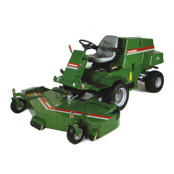
- Page 4 SERIAL NUMBER MACHINE NAME YEAR POWER WEIGHT Fig.1 GB-F-NL-2...
- Page 5 CONTENTS Page Safety Instructions ..............4 Engine and Machine Specification ..........12 Controls ..................18 Operation of the Machine ............26 Assembly of Cutting Units to Machine ........32 Lubrication and Maintenance Charts ........34 Cutting Performance ..............37 Lubrication ................40 Maintenance ................
-
Page 6: Safety Instructions
New safety labels are obtainable from Ransomes dealers. STARTING THE ENGINE Before starting the engine check that the brakes are Ce symbole de sécurité indique les messages de applied, drives are in neutral, guards are in position sécurité... -
Page 7: Veiligheidsvoorschriften
Nieuwe veiligheidsetiketten kunnen rechange auprès du Service de Pièces Détachées worden aangevraagd bij de Afdeling Onderdelen van de Ransomes. Ransomes (Ransomes Spare Parts Department). MISE EN ROUTE DU MOTEUR DE MOTOR STARTEN Avant de mettre le moteur en route vérifier que tous Controleer, voordat de motor wordt gestart, of de les freins sont mis, que les entraînements sont au... - Page 8 While mowing, always wear substantial footwear and long trousers. Do not operate the equipment when barefoot or wearing open sandals. Check the grass catcher frequently for wear or deterioration. After striking a foreign object. Inspect. the lawnmower for damage and make repairs before restarting and operating the equipment.
- Page 9 Verwijder of vermijd obstakels in het gebied dat N’oubliez jamais que l’opérateur ou l’utilisateur est wordt gemaaid, om te voorkomen dat uzelf en/of responsable des accidents dont peuvent être omstanders letsel oplopen. Let extra goed op victimes d’autres personnes ou leurs biens, ainsi que obstakels en/of omstanders wanneer de machine des risques auxquels ces personnes ou leurs biens achteruitrijdt.
-
Page 10: Adjustments, Lubrication And Maintenance
BLOCKED CUTTING CYLINDERS Stop the engine and make sure all moving parts are stationary. Apply brakes and disengage all drives. Release blockages with care. Keep all parts of the body away from the cutting edge. Beware of energy in the drive which can cause rotation when the blockage is released. - Page 11 Vermijd terreinomstandigheden waardoor de Vous devez être particulièrement prudent lorsque vous vous déplacez sur des pentes herbues. machine kan gaan slippen. De snelheid van de machine op hellingen en gedurende scherpe NE PAS UTILISER SUR DES PENTES bochten, zo laag mogelijk houden. SUPERIEURES A 15°...
- Page 12 WARNING: HYDRAULIC FLUID ESCAPING UNDER PRESSURE CAN PENETRATE SKIN AND DO SERIOUS DAMAGE. IMMEDIATE MEDICAL ASSISTANCE MUST BE SOUGHT. WARNING: BATTERIES PRODUCE EXPLOSIVE GASES AND CONTAIN CORROSIVE ACID AND SUPPLY LEVELS OF ELECTRICAL CURRENT HIGH ENOUGH TO CAUSE BURNS. THE OPERATING INSTRUCTIONS FOR THE FAIRWAY CUTTING UNITS ARE CONTAINED IN A SEPARATE PUBLICATION.
- Page 13 Let erop dat het voorgeschreven maximumtoerental Remettez soigneusement en place tous les van de motor niet wordt overschreden (zie de bouchons du réservoir et des récipients de motorspecificatie). De instellingen van de carburant. Rangez le carburant dans des récipients toerentalbegrenzer van de motor nooit wijzigen. Het spécialement prévus à...
-
Page 14: Engine Specification
SPECIFICATIONS ENGINE SPECIFICATION TYPE: Kubota 25KW (33HP) @ 3000 RPM, 4 cylinder (in line) vertical Diesel engine, 4 stroke, water cooled, 1335cc (81.47 cu.in) with 12V electric start. Model: V1305-BBS-EC-1 Maximum Speed: 3000 ± 50 RPM (No load) Idle Speed: 1500 Oil Sump Capacity: 6 litres (10.56 Imp.pints) (12.68 US pints) -
Page 15: Specificaties
SPECIFICATIES CARACTERISTIQUES MOTOR SPECIFICATIES TECHNIQUES Type: Kubota 25 kw @ 3000 tpm, 4-cilinder (in line) vertikale Diesel motor, 4-takt, CARACTERISTIQUES DU MOTEUR watergekoeld, 1335 cc, 12V elektrische Type: Moteur diesel 4 temps Kubota 25 kW (33 ontsteking. ch) à 3000 t/mn, 4 cylindres (en ligne) Model: V1305-BBS-EC-1 verticaux, refroidissement par eau, 1335... -
Page 16: Dimensions
ELECTRICAL SYSTEM Battery: Exide 134 Charging: 30amp alternator. Lights: Optional 2 headlights; indicators. Starting: 12 volt with 650amp cold cranking. Warning system: Audible alarm for high engine coolant temperature; low engine oil pressure; visual alarm for engine oil pressure; hydraulic oil temperature and charging system fuse and circuit breaker pro- tected. - Page 17 CIRCUIT ELECTRIQUE ELEKTRISCHE SYSTEEM Battery: Exide 134 Battery: Exide 134 Charge: Alternateur 30 A. plader: 30 amp generator Feux: 2 phares optionnels et clignotants. Lichten: Optioneel 2 koplampen; indicators Démarreur: 12 V, démarrage à froid manuel 650 A. Start: 12 volt met 650 amp koudstart Alarmes: Alarme sonore de surchauffe du liquide Waarschuwingssysteem:...
- Page 18 CUTTING DECKS Construction: Heavy duty welded steel. Deck drive: Hydraulic motor driving single poly vee belt. Cutter heads: 31.75mm (1.25in) diameter spindle with double sealed bearings. Blades: 1.52m (60 in) deck Three 533mm x 6mm (21in x .25in) heat treated blade. 1.60m (63in ) deck Three 558mm x 6mm (22in x .25in) heat treated blade.
- Page 19 DISPOSITIF DE COUPE MAAIBLADEN Réalisé en: acier soudé épais. Constructie: duurzaam gelast staal. Entraînement: moteur hydraulique entraînant une Aandrijving: hydraulische motor met enkele V-band courroie trapézoïdale à poulie unique. aandrijving. Têtes de coupe: axe de 31,75 mm de diamètre à Maaikoppen: 31,75 mm diameter as met dubbele belagering.
-
Page 20: Vibration Level
VIBRATION LEVEL The machine was tested for whole body and hand/ arm vibration levels. The operator was seated in the normal operating postion with both hands on the steering mechanism. The engine was running and the cutting device was rotating with the machine stationary. - Page 21 NIVEAU DES VIBRATIONS VIBRATIENIVEAU La machine a été soumise à des essais réalisés aux De machine is getest voor vibratie van het gehele niveaux des vibrations subies par le corps, les mains lichaam en hand-/armvibratie. De bestuurder zat in et bras. L’opérateur était assis normalement avec les de normale bedieningshouding met beide handen deux mains sur le volant.
- Page 22 CONTROLS THROTTLE CONTROL (A Fig.2) Push lever forward to increase engine speed. Pull back to reduce engine speed. IGNITION SWITCH (B Fig.2) The ignition key should be inserted and turned all the Fig.2 way clockwise to start engine. Let go of the key when engine starts.
- Page 23 BEDIENINGSHENDELS COMMANDES GASHENDEL (A Fig.2) ACCELERATEUR (A Fig.2) Duw de hendel naar voren om de motor sneller te Pousser le levier vers l’avant pour augmenter le laten draaien en naar achteren om de snelheid te régime moteur, le tirer vers l’arrière pour le réduire. laten afnemen.
- Page 24 FORWARD/REVERSE FOOTPEDAL (Fig.4) Using the right foot push down the upper part of the pedal for forward running and the rear part for reverse. Ground speed is increased the further the pedal is depressed. The pedal is spring controlled and will automatically return to the neutral position when the foot pressure is removed.
-
Page 25: Pedale De Marche Avant/Marche Arriere
VOETPEDAAL VOORUIT/ACHTERUIT (Fig.4) PEDALE DE MARCHE AVANT/MARCHE ARRIERE (Fig.4) Druk de bovenkant van het pedaal met de rechter voet in om vooruit te gaan en de onderkant om Avec le pied droit, enfoncer la partie supérieure de la achteruit te gaan. De rijsnelheid neemt toe naarmate pédale pour passer en M.AV., et la partie arrière het pedaal verder wordt ingedrukt. - Page 26 ALTERNATOR LIGHT (E Fig.7) Light comes on with the key in the start position and in the run position if the engine has not been started. Lamp will be illuminated while the engine is running if system is not charging. OIL LIGHT (F Fig.7) Light comes on at start up until engine builds up pressure then extinguishes.
- Page 27 GENERATORLAMPJE (E Fig.7) VOYANT ALTERNATEUR (E Fig.7) Ce voyant s’allume lorsque la clé est en position de Het lampje gaat branden door de sleutel op start te démarrage et en position marche (Run) si le moteur zetten en in de rijstand als de motor niet is gestart. n’a pas démarré.
-
Page 28: Operation Of The Machine
OPERATION OF THE MACHINE Read the Safety Instructions. STARTING THE ENGINE 1. Set throttle control to 1/2. Ensure PTO is disen- gaged and foot is not touching footpedal. If the foot pedal is not in the neutral position, the tractor will not start. 2. -
Page 29: Bediening Van De Machine
BEDIENING VAN DE FONCTIONNEMENT DU MACHINE MICROTRACTEUR Lire les instructions de sécurité Lees de veligheidsinstructies POUR DEMARRER MOTOR STARTEN Zet gashendel op 1/2. Zorg dat PTO is Mettre le levier d’accélération à mi-course. Vérifier que la prise de force n’est pas uitgeschakeld en het voetpedaal niet wordt enclenchée et que le pied n’est pas sur la ingedrukt. - Page 30 TO SLOW DOWN OR STOP MACHINE Gradually release the pressure on the footpedal. On inclines, move the pedal towards neutral till machine stops, and apply brake. CUTTING WITH THE MACHINE 1. Start the engine and run at lowest speed. 2. Lower the cutter deck. 3.
-
Page 31: Pour Ralentir Ou S'arreter
DE MACHINE LANGZAAM LATEN RIJDEN OF POUR RALENTIR OU S’ARRETER STOPPEN Relâcher progressivement la pédale. Sur des Verminder geleidelijk de druk op het voetpedaal. Zet surfaces inclinées, déplacer la pédale vers le point op hellingen het pedaal in zijn vrij tot de machine mort jusqu’à... - Page 32 PUSHING THE MACHINE WITH THE ENGINE STOPPED (Fig.9) This machine can be pushed or towed with the engine stopped. This can be accomplished as follows: a) Unscrew the cap U from the Free Wheel Valve b) Insert an allen wrench into the top of the Fig.9 exposed needle valve and rotate counterclockwise completely.
- Page 33 DE MACHINE VERPLAATSEN ZONDER MOTOR POUR POUSSER LE TRACTEUR AVEC LE (Fig.9) MOTEUR ARRETE (Fig.9) De machine kan worden voortgeduwd of getrokken Ce tracteur peut être poussé ou remorqué avec le als de motor uit is. Dit wordt als volgt bereikt: moteur arrêté.
- Page 34 ASSEMBLY OF CUTTER DECK TO TRACTOR NOTE: All references to right hand (RH) or left hand (LH) are with respect to the operator seated on the tractor. Fig.10 1. Start tractor and use implement lift to lower lift arms A. Make sure both arms are down as far as they will go.
-
Page 35: Montage Du Dispositif De Coupe Sur Le Microtracteur
MAAIBLAD OP TRACTOR MONTAGE DU DISPOSITIF MONTEREN DE COUPE SUR LE MICROTRACTEUR N.B.: Als wordt gerefereerd aan rechter hand (RH) of linker hand (LH), wordt REMARQUE: Les références aux côtés droit aangenomen dat de bestuurder op de (DR.) et gauche (GCHE.) tractor zit. - Page 36 12. Be sure hoses do not rub on tractor when raising or lowering cutter decks. 13. Make sure all tractor and cutterdeck tire pressures are set to 14 psi. (1 kg/cm ). Tires may be overinflated for shipping. 14. Check battery electrolyte level and charge. Use protective equipment such as, but not limited to, goggles, face shield, rubber gloves, and apron.
- Page 37 12. Zorg dat de slangen de tractor niet raken bij het 12. Vérifier que les flexibles ne frottent pas contre heffen en neerlaten van de maaibladen. une partie du tracteur lorsque le dispositif de coupe est relevé ou abaissé. 13. Zorg dat de druk van de tractor- en maaibladbanden ligt op 1 kg/cm².
- Page 38 SERVICE ITEM HOURS OF OPERATION FIRST 8 DAILY HOURS Check Interlock System Check / Top-up Engine Oil Level Check Hydraulic Oil Level Check / Top-up Coolant Level Check Water Separator Check Tyre Pressure Check/Clean Engine Compartment & Radiator Lubricate Grease Fittings (Cutter Deck Grease Fittings Daily) Clean air cleaner element Every 400 hours Unless Operating Under...
- Page 39 GB-F-NL-37...
- Page 40 GB-F-NL-38...
- Page 41 GB-F-NL-39...
-
Page 42: Lubrication
LUBRICATION • Lubricate every 50 working hours at arrows (except lubricate all cutter deck fittings daily). o l l o l l o l l o l l GB-F-NL-40... -
Page 43: Lubrification
SMERING LUBRIFICATION • Lubrifier toutes les 50 heures de marche aux • Smeren na elke 50 uur in bedrijf op de punten die points indiqués par les flèches (sauf pour tous de pijlen aangeven (Alle maaiblad aansluitpunten les embouts graisseurs du dispositif de coupe, dienen dagelijks te worden gesmeerd). - Page 44 ENGINE OIL (Check daily) (Fig.15 / 16) 1. Change engine oil and filter every 100 hours (See engine manual for more information.) a) First warm up the engine. Shut off engine when warm. b) Loosen bolts holding access cover R on the bottom of fuel tank and pivot to the side c) Remove oil drain plug and drain the oil from Fig.15...
- Page 45 HUILE MOTEUR (vérifier le niveau chaque jour) MOTOROLIE (dagelijk controleren) (Fig.15 / 16) (Fig.15 / 16) Ververs de motorolie en vervang het filter na elke 1. Changer l’huile et le filtre toutes les 100 heures 100 uur gebruik (Zie motorhandleiding voor meer (Pour de plus amples renseignements, voir le informatie.) manuel du moteur.)
- Page 46 MAINTENANCE Read the safety instructions COOLANT (Fig.17 / 18) Fill the radiator with a 50% anti-freeze solution to the correct level. The level is correct when the coolant Fig.17 is at the bottom of the filler neck. The overflow bottle O should normally be 1/4-1/2 full. To drain the cooling system, attach a 3/8 I.D.
-
Page 47: Radiateur En Motorkamer Reinigen
ONDERHOUD MAINTENANCE Lees de veiligheidsvoorschriften Lire les consignes de sécurité LIQUIDE DE REFROIDISSEMENT (Fig.17 / 18) KOELVLOEISTOF (Fig.17 / 18) Remplir le radiateur au niveau correct avec une Vul de radiateur met een 50% anti-vries oplossing tot solution d’antigel à 50 %. Le niveau est correct het juiste niveau. - Page 48 HYDRAULIC NOTES: • When any hydraulic port is opened, plug to reduce risk of contamination. • When checking for hydraulic leaks do not use your hands. Hydraulic fluid under pressure can get under skin and will require immediate medical attention. Use cardboard or similar method to check for leaks.
-
Page 49: Remarques : Equipement Hydraulique
OPMERKINGEN HYDRAULISCH SYSTEEM: REMARQUES : EQUIPEMENT HYDRAULIQUE • Sluit een geopende hydraulische leiding zo snel • Pendant toute intervention, boucher toute mogelijk weer af om het risico van vervuiling te ouverture sur le circuit hydraulique pour éviter une minimaliseren. contamination du fluide par l’humidité ambiante. •... - Page 50 WATER FUEL SEPARATOR (Fig.23) The machine is equipped with a water fuel separator. Water which can accumulate with the fuel is separated and trapped in the glass bowl. When approximately 1" (25mm) of water has been collected in the bowl, it should be drained off as follows: 2.
- Page 51 WATER BRANDSTOF SEPARATOR (Fig.23) SEPARATEUR EAU/GAZOLE (Fig.23) De machine is uitgerust met een water-brandstof Ce tracteur est équipé d’un séparateur eau/gazole separator. Water dat bij de brandstof is gekomen qui enlève l’eau ayant pu s’accumuler dans le wordt afgescheiden en opgevangen in de glazen bak. carburant et la recueille dans la cuve en verre.
- Page 52 Cleaning particle collector (every 50 hours) (Fig.27) 1. Remove end cover R and filter element 2. Reassemble with arrows on end cover pointing vertically upwards. BATTERY (Fig.28) Keep fluid levels above battery plates. Fig.27 WARNING Wear eye protection when servicing battery. OTHER REGULAR SERVICE •...
-
Page 53: Autres Operations D'entretien Regulier
Stofzak reinigen (na elke 50 uur) (Fig.27) Nettoyage du collecteur de particules (toutes les 50 heures) (Fig.27) Verwijder deksel R en het filterelement. 1. Enlever le couvercle R et l’élément du filtre. Na reinigen weer bevestigen, waarbij de pijltjes op het deksel recht omhoog moeten wijzen. 2. - Page 54 ADJUSTMENTS Read the safety instructions PARKING BRAKE (Fig.29 / 30) To loosen or tighten brakes: Fig.29 1. Adjust (2) brake cable nuts at P. 2. Additional adjustment can be made by removing the tractor wheels, following the cable to brake arm Q and adjusting both brake cable nuts at S.
- Page 55 AFSTELLINGEN REGLAGES Lees de veiligheidsvoorschriften Lire les consignes de sécurité PARKEERREM (Fig.29 / 30) FREIN DE PARKING (Fig.29 / 30) Losser of strakker instellen: Pour resserrer ou desserrer les freins: Stel de (2) remkabelmoeren bij P in. 1. Ajuster les (2) écrous du câble de frein P. Verdere afstelling kan worden bereikt door de 2.
- Page 56 FORWARD/REVERSE FOOTPEDAL (Fig.33 / 34) With the engine running and the footpedal latched into the neutral postion, the tractor should remain stationary. If it moves, correct as follows. IMPORTANT - Shut engine off between each adjustment. WARNING - Properly support raised machinery with jacks.
- Page 57 VOETPEDAAL VOORUIT/ACHTERUIT (Fig.33 / PEDALE M.AV./M.AR. (Fig.33 / 34) Avec le moteur en marche et la pédale de marche au Als de motor loopt en het voetpedaal in neutraalstand point mort, le tracteur doir rester stationnaire. S’il se is vergrendeld, loopt de tractor stationair. Als de déplace, corriger ce défaut comme suit.
- Page 58 SEAT (GRAMMER) The seat can be adjusted for operators weight and leg reach to provide a comfortable position for operating the machine. 1. ADJUSTMENT FOR OPERATOR WEIGHT The seat is adjustable for operator weights between 50Kgs (110lbs) and 130Kgs (285lbs). To Adjust: Fig.39 The position of the adjusting lever and weight gauge...
- Page 59 STOEL (GRAMMER) SIÈGE (GRAMMER) De stoel kan worden ingesteld op het gewicht en de Pour que la position de conduite soit confortable le beenruimte van de bestuurder, zodat de machine op siège peut être réglé en fonction du poids et de la comfortabele wijze kan worden bediend.
- Page 60 The cutting height is determined by the position of the blades in relation to the caster wheels. Changes to this height are made at (4) points and can be made in any order. For the following procedure, refer to the Height of Cut chart below.
- Page 61 De maaihoogte wordt bepaald door de positie van de La hauteur de coupe est déterminée par la position maaibladen t.o.v. de wielen. De maaihoogte kan op 4 des lames par rapport aux roulettes. Les plaatsen worden bijgesteld in willekeurige volgorde. changements de cette hauteur sont effectués en (4) Zie onderstaande Maaihoogte Kaart.
- Page 62 It is essential that the balance of the blades are maintained. NOTE: Always replace blades with original Ransomes blades, do not use another manufacturers blades. • Service the blades with the tractor turned off, and Fig.40...
- Page 63 REMARQUE: Toujours remplacer les lames avec des N.B.: Gebruik ter vervanging uitsluitend originele lames d’origine Ransomes; ne jamais utiliser une Ransomes bladen en geen bladen van een ander autre marque. merk. • Intervenir sur les lames avec le moteur coupé, le •...
- Page 64 Fig.43 GB-F-NL-62...
-
Page 65: Electrical System
ELECTRICAL SYSTEM BATTERY Cable Colour Code STARTER MOTOR ALTERNATOR ORANGE TEMPREATURE GAUGE BLACK TEMPREATURE SENDER FUEL GAUGE GREEN FUEL SENDER WHITE ENGINE OIL TEMPREATURE WARNING YELLOW LAMP PINK ENGINE OIL PRESSURE WARNING LAMP GREY BATTERY CHARGE WARNING LAMP BROWN GLOW PLUG WARNING LAMP BLUE GLOW PLUG LAMP TIMER DARK BLUE... - Page 66 Fig.42 GB-F-NL-64...
-
Page 67: Elektrisch Systeem
ELEKTRISCH SYSTEEM ELEKTRISCH SYSTEEM ACCU Kabelicleurcode STARTMOTOR Oranje WISSELSTROOMDYNAMO Zwan TEMPERATUURMETER Rood TEMPERATUURZENDER Groen BRAN DSTOFMETER BRANDSTOFZENDER Geel WAARSCHUWINGSLAMPJE Roze TEMPERATUUR MOTOROLIE Grijs WAARSGHUWINGSLAMPJE Bruin MOTOROLIEDRUK Blauw WMRSCHUW1NGSLAMPJE ACCULADER Donkerblauw WAARSCHUWINGSLAMPJE Lichtbiauw GLOEIBOUGIE TIMER GLOEIBOUGIELAMPJE GWEIBOUGIE RELAIS GLOElBOUGlES Zekeringen VOORUIT/ACHTERUIT NEUTRAAL Fl 3Oamp SCHAKELAAR F2 lOamp... - Page 68 Fig.42 GB-F-NL-66...
-
Page 69: Circuit Electrique
CIRCUIT ELECTRIQUE CIRCUIT ELECTRIQUE BATTERIE DEMARREUR ALTERNATEUR JAUGE DE TEMPERATURE TRANSMETTEUR DE TEMPERATURE JAUGE DE CARBURANT TRANSMETTEUR DE CARBURANT VOYANT DE TEMPERATURE D’HUILE MOTEUR VOYANT DE PRESSION D’HUILE VOYANT DE CHARGE DE BATTERIE VOYANT DE BOUGIE DE PRECHAUFFAGE MINUTERIE DE LAMPE DE BOUGIE DE PRECHAUFFAGE RELAIS DE BOUGIE DE PRECHAUFFAGE BOUGlES DE PRECHAUFFAGE... - Page 70 21 22 Fig.44 GB-F-NL-68...
-
Page 71: Hydraulic System
HYDRAULIC SYSTEM Unit Motor Valve Unit Lift Transmission Pump Lift Cylinder Relief valve 206.8bar (3000psi) Lift Cylinder Relief Valve 206.8bar (3000psi) To Steering Wheel Check Valve 13.8bar (200psi) Steering Unit Pump Steering Cylinder Hydraulic Tank Oil Cooler Inlet Manifold Suction Filter Flow Divider Valve 4 Wheel Drive Wheel Motor LH Front... - Page 72 GB-F-NL-70...
-
Page 73: Safety Decals
SAFETY DECALS 2000655: READ AND UNDERSTAND THE OPERATORS MANUAL BEFORE OPERATING 2000644: SERVICE/MAINTENANCE. Stop engine, remove key and spark plug wire before performing service or maintenance. Consult operators manual for procedures. 2000641: FLAMMABLE LIQUIDS - when refueling. Stop engine, do not smoke, do not spill fuel, do not overfill and allow 25mm for fuel expansion. - Page 74 GB-F-NL-72...
- Page 75 2000643 BLADE BOLT INSTALLATION Conical washer must be positioned as shown. See Operator’s Manual for blade changing instructions. 2000637 ROTATING PARTS Keep clear when engine is running. Do not operate with cover removed. 2000639 ROTATING BLADES Stay clear of blades when engine is running. Stop engine and let blades stop before removing grass collector or unclogging.
- Page 76 GB-F-NL-74...
-
Page 77: Instruction Decals
INSTRUCTION DECALS A903950: TYRE PRESSURE Tyre pressure in both wheels should be the same. 2000669: PARKING BRAKE Push down foot pedal to apply brake. Push down on foot pedal and pull up lever next to steering tower to release brake. 2000647: FOOT PEDAL Push front of pedal down for forward travel. - Page 78 Ransomes uses grade 5 bolts as standard (minimum commercial quality). Do not use lower quality bolts unless otherwise noted. BLADE BOLT TORQUE: 70 ft-lbs (95 Nm) WHEEL LUG NUTS: 55-65 ft-lbs (75-88 Nm) TORSIES Aanbevolen torsies (±...
- Page 79 ) t f ) t f ) t f ) t f ) t f ) t f ) t f ) t f ) t f ) t f GB-F-NL-77...
- Page 80 Ransomes' Dealer and that the defective part shall, if we so request, be returned to us or to the Dealer. This guarantee is in addition to, and...
-
Page 81: Garantie
Hierbij worden geen arbeidsloon, materiaalkosten of vervoerskosten binnen het Verenigd oninkrijk in rekening gebracht, op voorwaarde dat de vordering onder deze garantie wordt ingediend via een erkende Ransomes dealer en het defecte onderdeel, op ons verzoek, naar ons of naar de dealer wordt teruggezonden. - Page 82 GARANTIE Toutes nos machines neuves, sauf spécification contraires sur la facture, bénéficient d'une garantie de 12 mois pièces et main-d'oeuvre. Toutefois, la garantie ne sera pas acquise si: L'intervention technique est due à une cause autre que celle d'une utilisation normale du matériel, Des fournitures autres que celles prévues pour un fonctionnement correct ont été...
- Page 84 The following warning is for users of this product in California USA and is as required by proposition 65. CALIFORNIA Proposition 65 Warning Diesel engine exhaust and some of its constituents are known to the State of California to cause cancer, birth defects, and other reproductive harm.