Publicité
Les langues disponibles
Les langues disponibles
Liens rapides
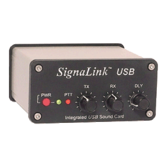
INTERFACE SIGNALINK USB
INSTALLATION ET FONCTIONNEMENT
Il y a toujours un risque d'endommager vos autres appareils. Par conséquent, il est extrêmement
important que vous preniez le temps de lire ces instructions d'installation pour éviter d'éventuels
problèmes.
- INTRODUCTION –
La SignaLink USB combine la performance légendaire de notre SL- 1 + avec l'intégration d'une
carte son à faible bruit.
Cette conception innovante offre de nombreux avantages par rapport aux interfaces traditionnelles
de la carte son que doit utiliser la carte son de l'ordinateur.
Il s'agit, notamment, des performances optimales, l'installation et le fonctionnement très simplifiée,
et la capacité de pouvoir facilement exécuter plusieurs interfaces sur un seul ordinateur en même
temps.
La SignaLink USB prend en charge tous les modes de son numérique et modes vocaux.
Ceci comprend les modes « traditionnels» tels que RTTY, SSTV et CW , ainsi que les modes
populaires comme le PSK31, MT- 63, JT65, ROS et EchoLink.
La performance sur tous les modes a été optimisée par l'utilisation de pièces spéciales à faible
bruit et une conception technique soignée, ainsi que des commandes de face avant pratiques qui
vous permettent de régler votre niveau de transmission audio ainsi que votre niveau de réception
audio, également un réglage de retard PTT.
La SignaLink USB est conçue et fabriquée en utilisant seulement les meilleurs composants de
haute qualité . Le montage se fait à l'aide des équipements de production robotisés.
Des tests rigoureux de chaque unité, et notre niveau élevé de contrôle de la qualité vous assure
d'un produit de qualité supérieure qui fournira de nombreuses années de service fiable.
Beaucoup d'efforts ont été consacrés à la conception et la fabrication de la SignaLink USB, et
nous pensons que vous serez d'accord que nous vous avons offert un niveau d'innovation, de
qualité et de valeur qui ne peut être égalé !
Publicité

Sommaire des Matières pour Signalink USB
- Page 1 Beaucoup d'efforts ont été consacrés à la conception et la fabrication de la SignaLink USB, et nous pensons que vous serez d'accord que nous vous avons offert un niveau d'innovation, de...
- Page 2 - Présentation de l'installation La SignaLink USB est facile à installer et à utiliser. Toutefois, si elle n'est pas installée et utilisée correctement, vous ne réaliserez pas sa meilleure performance et dans les cas extrêmes, vous ne pourrez pas fonctionner du tout.
- Page 3 Un câble radio avec le cas échéant un connecteur pour votre transceiver a été fourni avec la SignaLink USB dans ce but. Une extrémité de ce câble se branche sur le connecteur « RADIO » de la SignaLink, et l'autre extrémité se branche soit sur la prise Micro , data , ou accessoire de votre transceiver selon le modèle.
- Page 4 Au lieu de cela, vous aurez besoin de connecter le câble mono fourni par le haut-parleur externe ou casque de la prise du transceiver, à la prise SPKR sur le panneau arrière de la SignaLink USB. Cela va passer le signal audio HP du transceiver dans la SignaLink.
- Page 5 Parce que la SignaLink USB dispose de sa propre carte son intégrée, vous pourrez configurer Windows pour utiliser la carte son intégrée de la Signalink USB à la place de la carte son de votre ordinateur. Votre programme de communication peut alors être configuré pour utiliser uniquement le SignaLink USB.
- Page 6 SignaLink USB répertoriée comme ceci ( " USB Audio Codec " ). Cliquez sur le bouton OK et fermez le Panneau de configuration.
- Page 7 • Démarrez votre logiciel de communication et vérifier dans les paramètres de celui-ci que la carte son sélectionnée pour la transmission et la réception est " USB Audio Codec " ( c'est le nom de la carte son utilisée par la SignaLink USB ).
- Page 8 Si vous n'êtes pas sûr du mode à utiliser, consultez votre manuel. • Réglez Mic Gain contrôle du TX à 50 %. Notez que si la SignaLink est connectée à un port de données (data) ou accessoire, ce contrôle ne peut avoir aucun effet sur la puissance de sortie.
- Page 9 Figure 2 - fenêtre Propriétés • Le panneau de contrôle du volume s'ouvre alors. Réglez le Contrôle " Speaker " (contrôle gauche ) à un volume maximal de 100% , et réglez le Contrôle "Wave" à 50 % . Notez que les contrôles du haut parleur et Wave ne doivent pas être mis en sourdine (MUTE).
- Page 10 LED PTT allumée, voyez la section Dépannage à la fin de ce manuel. • Vous devriez maintenant être en mesure de régler le niveau « TX » de la SignaLink USB pour ajuster le niveau de puissance d' émission souhaitée ( voir la note importante ci-dessous ). Si vous ne pouvez pas obtenir une puissance suffisante, voyez les notes sur le cavalier JP3 en vertu de la Section "Cavaliers spécial "...
- Page 11 Interrupteur d'alimentation – Pour alimenter les circuits d’émission et de réception de la SignaLink USB, cet interrupteur ne coupe pas l’alimentation de la carte son intégrée. La carte son de la SignaLink USB n’est plus alimentée quand l’ordinateur est arrêté ou lorsque l’alimentation de celui-ci passe en mode veille.
- Page 12 Figure 4 - Emplacement des cavaliers JP2 , JP3 et JP4 .
-
Page 13: Support Technique
Assurez-vous que vous avez le logiciel et la documentation la plus récente disponible. Merci. Si vous rencontrez un problème que vous ne pouvez pas résoudre avec la SignaLink (pas logiciel), s'il vous plaît communiquez avec notre personnel de soutien technique au ( 541 ) 862- 2639. -
Page 14: Caractéristiques Générales
RX Audio / Spkr - 3,5 mm Mono Connecteur PC: USB 1.1/2.0 Compatible USB standard type "A" Conn Autres connecteurs : Aux . Speaker- 3,5 mm Mono Boîtier: en aluminium extrudé - 6061T4 Dimensions : 1.6 " x 3.2 " x 3.6 "... - Page 15 PTT ne dépasse pas la spécification du circuit de chiffrement SignaLink. Vérifiez que le PTT se fait par mise à la masse en émission et que le signal PTT ne dépasse pas 3 Ampères à 90V. Cela devrait être dans les notes de toutes les TX modernes mais pourrait être un problème sur certains matériels plus anciens.
- Page 16 à 1=1, 2=2, 3=3, etc sur chaque broche du connecteur radio de la Signalink USB. Vous vérifierez les numéros que vous avez enregistrés précédemment dans le manuel TX. Notez que si votre TX a un connecteur micro séparé, il peut y avoir une légère résistance par rapport à...
- Page 17 Si votre TX fourni une tension pour accessoires, vous pouvez mettre sous tension et utiliser votre multimètre (échelle volts) pour tester la puissance sur la broche appropriée de JP-1. La SignaLink USB n'utilise pas l’alimentation du TX, mais cette ligne peut toujours être utilisée à des fins de vérification.
- Page 18 Au lieu de cela, vous aurez besoin d'installer le câble mono fourni entre la prise casque de votre TX et la prise « SPKR » sur le panneau arrière du SignaLink USB. Cela va passer le signal haut- parleur du TX dans le SignaLink de sorte que l'appareil peut recevoir. Une fois que vous êtes sur que les cavaliers sont installés correctement, vous pouvez mettre la carte SignaLink Circuit USB...
- Page 19 «Réglage des niveaux audio". Si elles sont trop faibles, la SignaLink USB ne pourra pas transmettre. Le TX ne transmet pas mais la led PTT de la SignaLink est allumée - Si la led PTT de la SignaLink USB s'allume mais que le TX ne passe pas émission c’est que vous avez probablement un cavalier mal positionné...
- Page 20 Je n'arrive pas à recevoir - Il existe plusieurs causes possibles à ce problème: • Le contrôle du niveau RX SignaLink USB ou le contrôle du niveau BF du TX est trop faible - Vérifiez que la commande de niveau RX de la SignaLink RX est environ à moitié Si vous utilisez le haut parleur du TX (pas le niveau fixe du signal des ports Data / Accy Port), vérifiez que votre...
- Page 21 Si vous suivez pas à pas cette notice, il faut 15 minutes pour configurer l’interface et le logiciel que vous utilisez. Vous ne devez pas rencontrer de problèmes majeurs avec la Signalink. Il se peut qu’avec certains modes et certains TX vous rencontriez des anomalies qui, dans l’ensemble, sont assez simples à...
-
Page 22: Windows Vista
Setting the software Recording Levels (SignaLink SL-1 and SL-1+ only) Installing the SignaLink USB As with previous versions of Windows, the installation of the SignaLink USB on the computer is as simple as plugging the SignaLink into your computer's USB port. Windows will recognize the SignaLink USB's hardware, and after approximately 30 seconds (depending on the speed of your computer), the drivers will be automatically installed by the Operating System. - Page 23 ATTENTION WINDOWS 8 USERS: ATTENTION WINDOWS 8 USERS: You will need to first select the "Desktop" ATTENTION WINDOWS 8 USERS: ATTENTION WINDOWS 8 USERS: You will need to first select the "Desktop" You will need to first select the "Desktop" You will need to first select the "Desktop"...
- Page 24 If this is not possible, then you can leave it set to the SignaLink's sound card. SignaLink's sound card. We have not noticed any negative affects form doing this. We have not noticed any negative affects form doing this. SignaLink's sound card.
- Page 25 If you are using the SignaLink USB, then select "Speakers (USB Audio Codec)" as shown below. If you are using the SignaLink SL-1 or SL-1+, then you will need to select your computer's sound card since these products do not have a built-in sound card.
- Page 26 Applications volume control, then you will need to put your program in Transmit and re-open this window. 4. If you are using the SignaLink USB, then you should adjust the Speakers and Applications controls as shown above. Note that the Speakers control MUST be set to 100%, and the Applications control MUST be set to 50%.
- Page 27 "Wave" controls referred to in the SignaLink SL-1 and SL-1+ manuals. Please refer to the SignaLink manual for guidelines on setting these controls. Setting the software Recording Levels (SignaLink SL-1, SL-1+ only) NOTE: Do NOT use your communications program's "Set Transmit Levels" ("Transmitter...
- Page 29 4. You can now adjust the Microphone volume control and Microphone Boost Option (if available). Please refer to the guidelines in the SignaLink SL-1 and SL-1+ manuals to adjust the Microphone volume control, and Microphone Boost option. Click OK when done...
- Page 30 - Un-terminated cable (bare wires on radio end) for building your own cable Accessories: Accessories: Accessories: Accessories: • Plug & Play Jumper Modules - Click here for part numbers and radios supported • SLHEAD - SignaLink Programming Header for wiring your own jumper module...
- Page 31 While it is fairly simple to install the SignaLink, it is possible to DAMAGE YOUR RADIO or the information against your radio's manual before doing the actual installation. While it is fairly simple to install the SignaLink, it is possible to DAMAGE YOUR RADIO or the information against your radio's manual before doing the actual installation.
- Page 32 Kenwood, Yaesu, Some Others Kenwood, Yaesu, Some Others - You should verify in your radio manual that the radio PTT requirements do not exceed the specifications of the SignaLink keying circuit • (please refer to the SignaLink manual) and that the PTT line is “Grounded” to make the radio transmit. If your radio exceeds the specifications listed or requires some other keying arrangement, then please contact our Technical Support Staff for suggestions.
- Page 33 NOTE: making a mistake that could possibly damage the SignaLink or your radio. Note that the SignaLink USB does NOT use the PWR jumper wire, so you can disregard this jumper during installation. All other jumper settings are the same.
- Page 34 ALINCO 8 8 8 8 - - - - Pin Round Mic Connector Pin Round Mic Connector Pin Round Mic Connector Pin Round Mic Connector (use SLUSB8R, SL1+8R, SL1 (use SLUSB8R, SL1+8R, SL1 (use SLUSB8R, SL1+8R, SL1 (use SLUSB8R, SL1+8R, SL1- - - - 8R or SLCAB8R) 8R or SLCAB8R) 8R or SLCAB8R) 8R or SLCAB8R)
- Page 35 Notes Pin 1 – Mic Input TR-7/22/33 Power is not available on this connector, so you will Pin 2 – PTT UV-3 need to use external power for the SignaLink Model Pin 3 – N/C SL-1+. Pin 4 – GND...
- Page 36 Pin 7 - GND so you will need to use external power for the Pin 8 - GND SignaLink Model SL-1+. Elecraft K3 rear panel Audio In, Audio Out and PTT connectors Elecraft K3 rear panel Audio In, Audio Out and PTT connectors...
- Page 37 Pin 1 - Mic Two cable connections are required from the only Pin 2 - PTT SignaLink to the Elecraft KX3 as follows: Pin 3 - GND Pin 4 - NC Connect the RJ-45 end of the SLCABKX3 radio Pin 5 - NC cable to the SignaLink’s “Radio”...
- Page 38 If the SignaLink is attached to your radio's 8 If the SignaLink is attached to your radio's 8 If the SignaLink is attached to your radio's 8- - - - pin Accessory Port, then please see the pin Accessory Port, then please see the...
- Page 39 IC-761/765/775/781 IC-820H/901/910 IC-1201/1271/1275 IC-2400/2500 IC-3200/3210/3220/3230 IC-7400/7600/7700/7800 RJ- - - - 45 Mic Connector 45 Mic Connector 45 Mic Connector 45 Mic Connector (use SLUSBRJ4, SL1+RJ45, SL1 (use SLUSBRJ4, SL1+RJ45, SL1- - - - RJ45 or (use SLUSBRJ4, SL1+RJ45, SL1 (use SLUSBRJ4, SL1+RJ45, SL1 RJ45 or RJ45 or RJ45 or SLCABRJ4)
- Page 40 IC-703**/706MKIIG** Pin 6 – Squelch IC-746PRO** Power is not available on any 6-pin mini DIN Data Port, so IC-7000** you will need to use external power for the SignaLink Model IC-7100 SL-1+. IC-7400 IC-910H## **IC-703 - If you are using the Data Port on this radio, then ID-880 you must set menu #36 to "1200".
- Page 41 PORT only. If the SignaLink is attached to your radio's 8 If the SignaLink is attached to your radio's 8- - - - pin Round Mic Jack, then please see the If the SignaLink is attached to your radio's 8...
- Page 42 This will force the radio to use the same PTT pin wiring information. for all bands so you will not need to change the SignaLink's jumper settings. **The IC-718 does NOT mute the Mic jack when using the 13-pin Accy Port, so you will need to turn the Mic Gain down.
- Page 43 Pin-out Radio Models Notes Pin 1 - NC IC-251AE Pins marked as "NC" are not used by the SignaLink, Pin 2 - +13.8V IC-730/751 but might be connected internally inside the radio. Pin 3 - PTT Pin 4 - AF Out...
- Page 44 Pin 2 – PTT TR-7400A so you will need to use external power for Pin 3 – GND TR-7500 the SignaLink Model SL-1+. Pin 4 – Mic GND TS-120S/130S/180S TS-511S/520/530 TS-600/700/820/830 8 8 8 8 - - - - Pin Round Mic Connector...
- Page 45 TM-D710/710A/E Pin 6 – Squelch TM-G707 Power is not available on any 6-pin mini DIN Data Port, so TM-V708 you will need to use external power for the SignaLink TM-733A Model SL-1+. TM-V7/V7A/V71A TS-480HX/SAT **Only European models of the TM-271 and TM-271A have the 6-pin mini-DIN Data Port.
- Page 46 After you have installed the jumpers, be sure to set the sound card audio levels as outlined in the SignaLink manual. If you do not set the levels correctly, then the SignaLink may not transmit, and you might mistake the problem for incorrect jumper settings. Note that external power is required for the SignaLink Model SL-...
- Page 47 Pin 1 – Mic Input 13-510 Power is not available on this connector, so you will need to use Pin 2 – GND external power for the SignaLink Model SL-1+. Pin 3 – N/C Pin 4 – PTT RADIO SHACK...
- Page 48 Pegasus). However you should verify that your radio Pin 3 – PTT Scout has the same pin-out before installing them. Pin 4 – N/C Power is not available on this connector, so you will need to use external power for the SignaLink Model SL-1+.
- Page 49 Power is not available on this connector, so you will need to Pin 5 - NC use external power for the SignaLink Model SL-1+. 8 8 8 8 - - - - Pin DIN Accessory Connector Pin DIN Accessory Connector...
- Page 50 Pin 1 – GND FT-7B Power is not available on this connector, so you will need to Pin 2 – Mic Input FT-101/FT-101ZD use external power for the SignaLink Model SL-1+. Pin 3 – PTT FT-221 Pin 4 – N/C FT-227R...
- Page 51 RJ- - - - 11 Mic Connecto 11 Mic Connecto 11 Mic Connecto 11 Mic Connector r r r (use SLUSBRJ1, SL1 (use SLUSBRJ1, SL1- - - - RJ11, SL1+RJ11 or SLCABRJ1) (use SLUSBRJ1, SL1 (use SLUSBRJ1, SL1 RJ11, SL1+RJ11 or SLCABRJ1) RJ11, SL1+RJ11 or SLCABRJ1) RJ11, SL1+RJ11 or SLCABRJ1) JP- - - - 1 1 1 1...
- Page 52 **The FT-1000MPMKV and FT-1000MKV Field MUST be in "Packet" mode FTDX-9000/D/MP (NOT usb!) for digital operation. For PSK31 or other "USB" digital modes, you'll need to set your radio's "User Mode" (selection 8-6) to "PS31U". This will configure the radio to look at the Packet jack and use the correct side band for PSK31.
- Page 53 **FT-450 - Some users have reported that this radio has a very FT-7900R sensitive Data Port, making power adjustments with the SignaLink FT-8100 USB's TX knob somewhat touchy. If this is the case with your radio, FT-8500 then please click here for a simple solution to this problem.
- Page 54 NOTE: This jack works great on HF, but it does not appear to work on VHF/UHF. For VHF/UHF operation, you'll need to use the 8-pin Mic jack, or the 6-pin mini-DIN Data Port. For HF operation on the FT-847, we recommend that you attach the SignaLink to the "Data I/O" jack. This jack works for virtually all sound card digital and voice modes, and will let you keep your microphone plugged into the radio.
- Page 55 3) Câblage sur connecteur Patch + AF out + PTT Cette dernière solution présente l’avantage de pouvoir transmettre en modes digitaux en USB ce qui n’est pas possible avec la DIN 5 broches contrairement à des transceivers plus récents. Le soft du FT-1000 ne permet pas de choisir entre LSB et USB.
- Page 56 Schéma de câblage Prise RJ45 Signalink VUE DU DESSUS Connecteur PTT 8 Ground 7 Ground 6 Ground 5 --- Connecteur PATCH 4 --- 3 PTT 2 MIC 1 SPK Connecteur AF OUT On prendra soin d’utiliser du câble informatique blindé et d’ajouter une ferrite clipsable au ras du connecteur RJ45...
- Page 57 Our new "Plug & Play" jumper modules plug into the SignaLink in place of the jumper wires that you would normally use to configure the un Our new "Plug & Play" jumper modules plug into the SignaLink in place of the jumper wires that you would normally use to configure the unit for your radio.
- Page 58 13-pin Accy Port. For a list of compatible radios please click here. NOTE: This module works with the SignaLink USB only. It is physically too tall to fit inside the older SignaLink SL-1+ model "as is", although some customers have trimmed the PTT jumper leads to make it fit.
- Page 59 Module Insertion Module Insertion - - - - To install the jumper module, place it lightly on the SignaLink's JP1 jumper socket being careful to align the notch on the jumper To install the jumper module, place it lightly on the SignaLink's JP1 jumper socket being careful to align the notch on the jumper...
- Page 60 SignaLink's socket. in the SignaLink's socket. This is NOT covered under warranty and you would need to return the SignaLink to the factory to have the socket replaced, as well as in the SignaLink's socket.