
Manuels Connexes pour AERMEC FCX 24USPO


Sommaire des Matières pour AERMEC FCX 24USPO
- Page 1 FCX US P FCX US PO FCX US Technical Manual Manuel Technique FCX US FAN COIL VENTILO-CONVECTEURS FCX USP FCX USPO IFCXUSTN 1505 - 4033750_04...
- Page 2 AERMEC S.p.A AERMEC S.p.A. reserves the right to make any modifications considered necessary to improve its products at any moment and is not obliged to add these modifications to machines that have already been manufactured, delivered or are under construction.
- Page 3 MODÈLE PLUS ACCESSOIRES : Il est interdit de faire fonctionner l’appareil avec des accessoires qui ne sont pas fournis de Aermec. MODELL + ZUBEHÖR : Falls das Gerät mit Zubehörteilen ausgerüstet wird, die nicht von Aermec geliefert werden, ist dessen Inbetriebnahme solange untersagt.
- Page 4 TRASPORTO • TRANSPORT • TRANSPORT • TRANSPORT • TRANSPORTE NON bagnare. Tenere al KEEP DRY. Keep out of the NE PAS mouiller. Tenir à l’abri NICHT nass machen. Vor NO mojar. Conservar protegi- riparo dalla pioggia. rain. de la pluie. Regen geschützt anbringen do de la lluvia.
-
Page 5: Emballage
échelle mécanique, d'echauf- faudages ou d'autres systèmes de levée employés pour AERMEC S.p.A. declines all responsibility for any damage effectuer des interventions en garantie. whatsoever caused by improper use of the machine, and a partial or superficial acquaintance with the information con- AERMEC S.p.A. -
Page 6: Table Des Matières
Index 4-Rows coil heating capacity - puissance thermique rendement Description of the unit - description de l’unite ..........7 batterie à 4 rangs ..................40 Main components - composants principaux ..........8 Single-row coil heating capacity - puissance thermique rendement batterie à 1 rang ...................... -
Page 7: Description Of The Unit - Description De L'unite
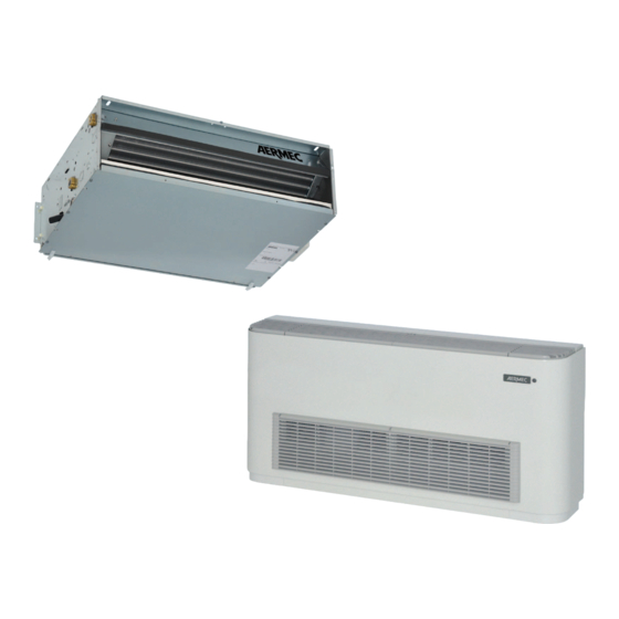
DESCRIPTION of the unit - description de l’unite DESCRIPTION DESCRIPTION DE L’UNITE PURPOSE OF THE UNIT BUT DE L’APPAREIL The fan coil unit treats room air during summer (cooling) Le ventiloconvecteur est une unité terminale servant au trai- and winter (heating). tement de l’air d’un milieu tant en hiver qu’en été. -
Page 8: Description Des Composants - Batterie D'echange Thermique
MAIN COMPONENTS • COMPOSANTS PRINCIPAUX 1. DESCRIPTION OF COMPONENTS - DESCRIPTION DES COMPOSANTS MAIN COMPONENTS • COMPOSANTS PRINCIPAUX 1 Control panel (optional) • Panneau des commandes (optio- 6 Fan • Ventilateurs nal) 7 Bearing structure • Structure portante 2 Heat exchanger • Batterie d’échange thermique 8 Condensate discharge •... - Page 9 damping elastic supports. jours enclenché, directement accouplé aux ventilateurs et amorti à l'aide de supports élastiques. - MAIN FRAME - STRUCTURE PORTANTE Made from adequately sized galvanized sheet steel. The rear section features holes for wall-mounting. Hanging models Réalisée en tôle zinguée d’une épaisseur appropriée. Dans la also feature a front cover panel over the fan assembly.
-
Page 10: Selection Criteria - Critères De Choix
SELECTION CRITERIA - critÈRES DE CHOIX SELECTION CRITERIA CRITÈRES DE CHOIX Les versions verticales (US) sont équipées de reprise à l'avant, Vertical cabinet versions (US) feature frontal air intake, and are installations verticales au mur. suited for vertical wall installation. Les versions suspendues (USP-USPO), sans carrosserie et avec repri- Hanging versions (USP-USPO) come without housing and fea- se par le bas, conviennent aussi bien aux installation horizontales. -
Page 11: Technical Data - Donnees Techniques - Fcx Us - Usp - 3 Row - 3 Rangs - Metric System
TECHNICAL DATA • DONNEES TECHNIQUES - FCX US - USP - 3 ROW - 3 RANGS - METRIC SYSTEM TAB 1 - FCX US - USP TECHNICAL DATA • DONNEES TECHNIQUES FCX US - USP Mod. FCX US - USP (3 row • 3 rangs) max. -
Page 12: Technical Data - Donnees Techniques - Fcx Us - Usp - 3 Row - 3 Rangs - Us System
TECHNICAL DATA • DONNEES TECHNIQUES - FCX US - USP - 3 ROW - 3 RANGS - US SYSTEM TAB 1 A - FCX US - USP TECHNICAL DATA • DONNEES TECHNIQUES FCX US - USP Mod. FCX US - USP (3 row • 3 rangs) max. -
Page 13: Technical Data - Donnees Techniques - Fcx Uspo - 3 Row - 3 Rangs - Metric System
TECHNICAL DATA • DONNEES TECHNIQUES - FCX USPO - 3 ROW - 3 RANGS - METRIC SYSTEM TAB 2 - TECHNICAL DATA FCX USPO (3 ROW) • DONNEES TECHNIQUES FCX USPO (3 RANGS) Mod. FCX USPO (3 row • 3 rangs) Heating capacity max.(*) 3400... -
Page 14: Technical Data - Donnees Techniques - Fcx Uspo - 3 Row - 3 Rangs - Us System
TECHNICAL DATA • DONNEES TECHNIQUES - FCX USPO - 3 ROW - 3 RANGS - US SYSTEM TAB 2 A - TECHNICAL DATA FCX USPO (3 ROW) • DONNEES TECHNIQUES FCX USPO (3 RANGS) Mod. FCX USPO (3 row • 3 rangs) Heating capacity max.(*) [Btu/hr]... -
Page 15: Technical Data - Donnees Techniques - Fcx Usp - 4 Row - 4 Rangs - Metric System
TECHNICAL DATA • DONNEES TECHNIQUES - FCX USP - 4 ROW - 4 RANGS - METRIC SYSTEM TAB 3 - TECHNICAL DATA FCX USP (4 ROW) • DONNEES TECHNIQUES FCX USP (4 RANGS) Mod. FCX USP (4 row • 4 rangs) max. -
Page 16: Technical Data - Donnees Techniques - Fcx Usp - 4 Row - 4 Rangs - Us System
TECHNICAL DATA • DONNEES TECHNIQUES - FCX USP - 4 ROW - 4 RANGS - US SYSTEM TAB 3 A - TECHNICAL DATA FCX USP (4 ROW) • DONNEES TECHNIQUES FCX USP (4 RANGS) Mod. FCX USP (4 row • 4 rangs) max. -
Page 17: Technical Data - Donnees Techniques - Fcx Uspo - 4 Row - 4 Rangs - Metric System
TECHNICAL DATA • DONNEES TECHNIQUES - FCX USPO - 4 ROW - 4 RANGS - METRIC SYSTEM TAB 4 - TECHNICAL DATA FCX USPO (4 ROW) • DONNEES TECHNIQUES FCX USPO (4 RANGS) Mod. FCX USPO (4 row • 4 rangs) Heating capacity max.(*) 3950... -
Page 18: Technical Data - Donnees Techniques - Fcx Uspo - 4 Row - 4 Rangs - Us System
TECHNICAL DATA • DONNEES TECHNIQUES - FCX USPO - 4 ROW - 4 RANGS - US SYSTEM TAB 4 A - TECHNICAL DATA FCX USPO (4 ROW) • DONNEES TECHNIQUES FCX USPO (4 RANGS) Mod. FCX USPO (4 row • 4 rangs) Heating capacity max.(*) [Btu/hr]... -
Page 19: Operating Limits - Limites De Fonctionnement
OPERATING LIMITS - LIMITES DE FONCTIONNEMENT OPERATING LIMITS LIMITES DE FONCTIONNEMENT Maximum water inlet temperature ....176°F / 80 °C Température maximale d’entrée de l’eau ..176°F / 80 °C Maximum working pressure ......115psi / 8 bar Pression maximale de fonctionnement ..115psi / 8 bar The assembling place must be chosen so that the max. -
Page 20: Cooling Capacity Correction Factors (3 Rows) - Facteurs De Correction De La Puis- Sance Frigorifique (3 Rangs)
COOLING CAPACITY CORRECTION FACTORS (3 ROWS) - FACTEURS DE CORRECTION DE LA PUISSANCE FRIGORIFIQUE (3 RANGS) COOLING CAPACITY CORRECTION FACTORS (4 ROWS) - FACTEURS DE CORRECTION DE LA PUISSANCE FRIGORIFIQUE (4 RANGS) COOLING CAPACITY CORRECTION FACTORS (3 ROWS) FACTEURS DE CORRECTION DE LA PUISSANCE FRIGORIFIQUE (3 RANGS) The cooling capacities in the tables from TAB. -
Page 21: Delivered Cooling Capacity - Puissance Frigorifique Delivree
DELIVERED COOLING CAPACITY - PUISSANCE FRIGORIFIQUE DELIVREE TAB 5 FCX 17 - DELIVERED COOLING CAPACITY • PUISSANCE FRIGORIFIQUE DELIVREE TOTAL COOLING CAPACITY (W) SENSIBLE COOLING CAPACITY (W) PUISSANCE FRIGORIFIQUE TOTALE (W) PUISSANCE FRIGORIFIQUE SENSIBLE (W) Water temp. Wet bulb air temperature (°C) Dry bulb air temperature (°C) Inlet (°C) Température air bulbe humide (°C) - Page 22 TAB 5 A FCX 17 - DELIVERED COOLING CAPACITY • PUISSANCE FRIGORIFIQUE DELIVREE TOTAL COOLING CAPACITY (Btu/hr) SENSIBLE COOLING CAPACITY (Btu/hr) PUISSANCE FRIGORIFIQUE TOTALE (Btu/hr) PUISSANCE FRIGORIFIQUE SENSIBLE (Btu/hr) Water temp. Wet bulb air temperature (°F) Dry bulb air temperature (°F) Inlet (°F) Température air bulbe humide (°F) Température air bulbe sèch (°F)
- Page 23 TAB 6 FCX 22 - DELIVERED COOLING CAPACITY • PUISSANCE FRIGORIFIQUE DELIVREE TOTAL COOLING CAPACITY (W) SENSIBLE COOLING CAPACITY (W) PUISSANCE FRIGORIFIQUE TOTALE (W) PUISSANCE FRIGORIFIQUE SENSIBLE (W) Water temp. Wet bulb air temperature (°C) Dry bulb air temperature (°C) Inlet (°C) Température air bulbe humide (°C) Température air bulbe sèch (°C)
- Page 24 TAB 6 A FCX 22 - DELIVERED COOLING CAPACITY • PUISSANCE FRIGORIFIQUE DELIVREE TOTAL COOLING CAPACITY (Btu/hr) SENSIBLE COOLING CAPACITY (Btu/hr) PUISSANCE FRIGORIFIQUE TOTALE (Btu/hr) PUISSANCE FRIGORIFIQUE SENSIBLE (Btu/hr) Water temp. Wet bulb air temperature (°F) Dry bulb air temperature (°F) Inlet (°F) Température air bulbe humide (°F) Température air bulbe sèch (°F)
- Page 25 TAB 7 FCX 32 - DELIVERED COOLING CAPACITY • PUISSANCE FRIGORIFIQUE DELIVREE TOTAL COOLING CAPACITY (W) SENSIBLE COOLING CAPACITY (W) PUISSANCE FRIGORIFIQUE TOTALE (W) PUISSANCE FRIGORIFIQUE SENSIBLE (W) Water temp. Wet bulb air temperature (°C) Dry bulb air temperature (°C) Inlet (°C) Température air bulbe humide (°C) Température air bulbe sèch (°C)
- Page 26 TAB 7 A FCX 32 - DELIVERED COOLING CAPACITY • PUISSANCE FRIGORIFIQUE DELIVREE TOTAL COOLING CAPACITY (Btu/hr) SENSIBLE COOLING CAPACITY (Btu/hr) PUISSANCE FRIGORIFIQUE TOTALE (Btu/hr) PUISSANCE FRIGORIFIQUE SENSIBLE (Btu/hr) Water temp. Wet bulb air temperature (°F) Dry bulb air temperature (°F) Inlet (°F) Température air bulbe humide (°F) Température air bulbe sèch (°F)
- Page 27 TAB 8 FCX 42 - DELIVERED COOLING CAPACITY • PUISSANCE FRIGORIFIQUE DELIVREE TOTAL COOLING CAPACITY (W) SENSIBLE COOLING CAPACITY (W) PUISSANCE FRIGORIFIQUE TOTALE (W) PUISSANCE FRIGORIFIQUE SENSIBLE (W) Water temp. Wet bulb air temperature (°C) Dry bulb air temperature (°C) Inlet (°C) Température air bulbe humide (°C) Température air bulbe sèch (°C)
- Page 28 TAB 8 A FCX 42 - DELIVERED COOLING CAPACITY • PUISSANCE FRIGORIFIQUE DELIVREE TOTAL COOLING CAPACITY (Btu/hr) SENSIBLE COOLING CAPACITY (Btu/hr) PUISSANCE FRIGORIFIQUE TOTALE (Btu/hr) PUISSANCE FRIGORIFIQUE SENSIBLE (Btu/hr) Water temp. Wet bulb air temperature (°F) Dry bulb air temperature (°F) Inlet (°F) Température air bulbe humide (°F) Température air bulbe sèch (°F)
- Page 29 TAB 9 FCX 50 - DELIVERED COOLING CAPACITY • PUISSANCE FRIGORIFIQUE DELIVREE TOTAL COOLING CAPACITY (W) SENSIBLE COOLING CAPACITY (W) PUISSANCE FRIGORIFIQUE TOTALE (W) PUISSANCE FRIGORIFIQUE SENSIBLE (W) Water temp. Wet bulb air temperature (°C) Dry bulb air temperature (°C) Inlet (°C) Température air bulbe humide (°C) Température air bulbe sèch (°C)
- Page 30 TAB 9 A FCX 50 - DELIVERED COOLING CAPACITY • PUISSANCE FRIGORIFIQUE DELIVREE TOTAL COOLING CAPACITY (Btu/hr) SENSIBLE COOLING CAPACITY (Btu/hr) PUISSANCE FRIGORIFIQUE TOTALE (Btu/hr) PUISSANCE FRIGORIFIQUE SENSIBLE (Btu/hr) Water temp. Wet bulb air temperature (°F) Dry bulb air temperature (°F) Inlet (°F) Température air bulbe humide (°F) Température air bulbe sèch (°F)
- Page 31 TAB 10 FCX 62 - DELIVERED COOLING CAPACITY • PUISSANCE FRIGORIFIQUE DELIVREE TOTAL COOLING CAPACITY (W) SENSIBLE COOLING CAPACITY (W) PUISSANCE FRIGORIFIQUE TOTALE (W) PUISSANCE FRIGORIFIQUE SENSIBLE (W) Water temp. Wet bulb air temperature (°C) Dry bulb air temperature (°C) Inlet (°C) Température air bulbe humide (°C) Température air bulbe sèch (°C)
- Page 32 TAB 10 A FCX 62 - DELIVERED COOLING CAPACITY • PUISSANCE FRIGORIFIQUE DELIVREE TOTAL COOLING CAPACITY (Btu/hr) SENSIBLE COOLING CAPACITY (Btu/hr) PUISSANCE FRIGORIFIQUE TOTALE (Btu/hr) PUISSANCE FRIGORIFIQUE SENSIBLE (Btu/hr) Water temp. Wet bulb air temperature (°F) Dry bulb air temperature (°F) Inlet (°F) Température air bulbe humide (°F) Température air bulbe sèch (°F)
- Page 33 TAB 11 FCX 82 - DELIVERED COOLING CAPACITY • PUISSANCE FRIGORIFIQUE DELIVREE TOTAL COOLING CAPACITY (W) SENSIBLE COOLING CAPACITY (W) PUISSANCE FRIGORIFIQUE TOTALE (W) PUISSANCE FRIGORIFIQUE SENSIBLE (W) Water temp. Wet bulb air temperature (°C) Dry bulb air temperature (°C) Inlet (°C) Température air bulbe humide (°C) Température air bulbe sèch (°C)
- Page 34 TAB 11 A FCX 82 - DELIVERED COOLING CAPACITY • PUISSANCE FRIGORIFIQUE DELIVREE TOTAL COOLING CAPACITY (Btu/hr) SENSIBLE COOLING CAPACITY (Btu/hr) PUISSANCE FRIGORIFIQUE TOTALE (Btu/hr) PUISSANCE FRIGORIFIQUE SENSIBLE (Btu/hr) Water temp. Wet bulb air temperature (°F) Dry bulb air temperature (°F) Inlet (°F) Température air bulbe humide (°F) Température air bulbe sèch (°F)
- Page 35 TAB 12 FCX 102 - DELIVERED COOLING CAPACITY • PUISSANCE FRIGORIFIQUE DELIVREE TOTAL COOLING CAPACITY (W) SENSIBLE COOLING CAPACITY (W) PUISSANCE FRIGORIFIQUE TOTALE (W) PUISSANCE FRIGORIFIQUE SENSIBLE (W) Water temp. Wet bulb air temperature (°C) Dry bulb air temperature (°C) Inlet (°C) Température air bulbe humide (°C) Température air bulbe sèch (°C)
- Page 36 TAB 12 A FCX 102 - DELIVERED COOLING CAPACITY • PUISSANCE FRIGORIFIQUE DELIVREE TOTAL COOLING CAPACITY (Btu/hr) SENSIBLE COOLING CAPACITY (Btu/hr) PUISSANCE FRIGORIFIQUE TOTALE (Btu/hr) PUISSANCE FRIGORIFIQUE SENSIBLE (Btu/hr) Water temp. Wet bulb air temperature (°F) Dry bulb air temperature (°F) Inlet (°F) Température air bulbe humide (°F) Température air bulbe sèch (°F)
-
Page 37: 3-Rows Coil Heating Capacity - Puissance Thermique Rendement Batterie À 3 Rangs
3-ROWS COIL HEATING CAPACITY • PUISSANCE THERMIQUE RENDEMENT BATTERIE À 3 RANGS 3-ROWS COIL HEATING CAPACITY • PUISSANCE THERMIQUE RENDEMENT BATTERIE À 3 RANGS 3-ROW HEATING CAPACITY CORRECTION FACTORS FACTEURS DE CORRECTION DE LA PUISSANCE THERMIQUE AVEC BATTERIE 3 RANGS Capacities are referred to high speed. - Page 38 TAB 15 FCX 32 MODEL • MODELE FCX 32 ∆t (temperature entering water - temperature entering air) • ∆t (température eau à l’entrée - température air à l’entrée) 20°C 30°C 40°C 50°C 60°C 70°C 68°F 86°F 104°F 122°F 140°F 158°F 7,5 kW kBtu/h Heating Capacity •...
- Page 39 TAB 18 FCX 62 MODEL • MODELE FCX 62 ∆t (temperature entering water - temperature entering air) • ∆t (température eau à l’entrée - température air à l’entrée) 2100 20°C 30°C 40°C 50°C 60°C 70°C 1900 68°F 86°F 104°F 122°F 140°F 158°F 1700...
-
Page 40: 4-Rows Coil Heating Capacity - Puissance Thermique Rendement Batterie À 4 Rangs
4-ROWS COIL HEATING CAPACITY • PUISSANCE THERMIQUE RENDEMENT BATTERIE À 4 RANGS 4-ROWS COIL HEATING CAPACITY • PUISSANCE THERMIQUE RENDEMENT BATTERIE À 4 RANGS Capacities are referred to high speed. To obtain values for other speed, multiply the values read by following factors: Les rendements thermiques se rapportent à... - Page 41 TAB 24 FCX 54 MODEL • MODELE FCX 54 ∆t (temperature entering water - temperature entering air) • ∆t (température eau à l’entrée - température air à l’entrée) 1050 20°C 30°C 40°C 50°C 60°C 70°C 68°F 86°F 104°F 122°F 140°F 158°F kBtu/h Heating Capacity •...
-
Page 42: Single-Row Coil Heating Capacity Puissance Thermique Rendement Batterie À 1 Rang
SINGLE-ROW COIL HEATING CAPACITY - PUISSANCE THERMIQUE RENDEMENT BATTERIE À 1 RANG SINGLE-ROW COIL HEATING CAPACITY PUISSANCE THERMIQUE RENDEMENT BATTERIE À 1 RANG The performance of the 3R+1R versions can be calculated from TAB. 27 to 34 concerning the standard coils with the fac- tors here below. - Page 43 TAB 29 FCX 32 MODEL • MODELE FCX 32 ∆t (temperature entering water - temperature entering air) • ∆t (température eau à l’entrée - température air à l’entrée) 1.75 20°C 30°C 40°C 50°C 60°C 70°C 68°F 86°F 104°F 122°F 140°F 158°F 1.50 1.25...
- Page 44 TAB 32 FCX 62 MODEL • MODELE FCX 62 ∆t (temperature entering water - temperature entering air) • ∆t (température eau à l’entrée - température air à l’entrée) 20°C 30°C 40°C 50°C 60°C 70°C 68°F 86°F 104°F 122°F 140°F 158°F 12 14 18 20 24 26...
-
Page 45: Direct Expansion Coil Cooling Capacity Puissance Frigorifique Rendement Batterie À Détente Directe
DIRECT EXPANSION COIL COOLING CAPACITY - PUISSANCE FRIGORIFIQUE RENDEMENT BATTERIE À DÉTENTE DIRECTE DIRECT EXPANSION COIL COOLING CAPACITY PUISSANCE FRIGORIFIQUE RENDEMENT BATTERIE À DÉTENTE DIRECTE The cooling capacities in the tables 35 to 41 are with reference to the maximum speed. For the other speeds, the values must be multiplied by the following factors: Les rendements du tableaux 35 à... - Page 46 TAB 37 MODEL FCX 42• FCX 42 MODELE Total capacity • Rendement total Sensible capacity • Rendement sensible kBtu/h kBtu/h 11.9 23.9 20.5 10.2 17.0 13.6 10.2 31 °C °C 62.6 66.2 69.8 73.4 75.2 °F 69.8 73.4 80.6 84.2 87.8 °F wet bulb temperature intake air dry bulb temperature intake air...
- Page 47 TAB 40 MODEL FCX 82 • FCX 82 MODELE Sensible capacity • Rendement sensible Total capacity • Rendement total kBtu/h kBtu/h 23.9 44.4 37.6 20.5 30.7 17.1 23.9 13.6 17.1 10.2 10.2 °C 31 °C 62.6 66.2 69.8 73.4 75.2 °F 69.8 73.4...
-
Page 48: Hanging Versions Head - Pression Statique Utile Des Versions Suspendues
HANGING VERSIONS HEAD • PRESSION STATIQUE UTILE DES VERSIONS SUSPENDUES HANGING VERSIONS HEAD • PRESSION STATIQUE UTILE DES VERSIONS SUSPENDUES Les ventiloconvecteurs de la série USPO ont été conçus USPO series fancoils have been designed to adjust available static pressure provided by the fan to pressure drop in the pour permettre d'adapter la pression statique fournie par le ducting system by selecting the appropriate operating speed. - Page 49 TAB 44 FCX 42 - 44 MODEL • MODELE FCX 42- 44 L1: max. speed USPO version • vit. maxi version USPO max. speed version USP • vit. maxi version USP L7: min. speed USPO version • vit. mini version USPO min.
- Page 50 TAB 46 FCX 62 - 64 MODEL • MODELE FCX 62 - 64 L1: max. speed USPO version • vit. maxi version USPO max. speed version USP • vit. maxi version USP L7: min. speed USPO version • vit. mini version USPO min.
- Page 51 3-ROWS COIL PRESSURE DROP - PERTES DE CHARGE BATTERIE À 3 RANGS SINGLE-ROW COIL PRESSURE DROP PERTES DE CHARGE BATTERIE À 1 RANG TAB 49 3-ROWS COIL PRESSURE DROP PERTES DE CHARGE BATTERIE À 3 RANGS ft. wg FCX 32 17.5 FCX 42 FCX 17-22...
-
Page 52: 4-Rows Coil Pressure Drop - Pertes De Charge Batterie À 4 Rangs
4-ROWS COIL PRESSURE DROP - PERTES DE CHARGE BATTERIE À 4 RANGS TAB 51 4-ROWS COIL PRESSURE DROP PERTES DE CHARGE BATTERIE À 4 RANGS ft. wg FCX 64 31.5 24.5 FCX 44 FCX 84 17.5 FCX 54 FCX 34 FCX 24 10.5 2200... -
Page 53: Correction Factors In Cooling Operation With Glycol Water - Facteurs De Correction En Mode Refroidissement Avec Eau Additionnée De Glycol
CORRECTION FACTORS IN COOLING OPERATION WITH GLYCOL WATER - FACTEURS DE CORRECTION EN MODE REFROIDISSEMENT AVEC EAU ADDI- TIONNÉE DE GLYCOL CORRECTION FACTORS IN COOLING OPERATION WITH GLYCOL WATER FACTEURS DE CORRECTION EN MODE REFROIDISSEMENT AVEC EAU ADDITIONNÉE DE GLYCOL TAB 52 GLYCOL WATER AT 10% •... -
Page 54: Correction Factors In Heating Operation With Glycol Water Facteurs De Correction En Mode Chauffage Avec Eau Additionnée De Glycol
CORRECTION FACTORS IN HEATING OPERATION WITH GLYCOL WATER - FACTEURS DE CORRECTION EN MODE CHAUFFAGE AVEC EAU ADDITIONNÉE DE GLYCOL CORRECTION FACTORS IN HEATING OPERATION WITH GLYCOL WATER FACTEURS DE CORRECTION EN MODE CHAUFFAGE AVEC EAU ADDITIONNÉE DE GLYCOL TAB 55 GLYCOL WATER AT 10% •... -
Page 55: Sound Pressure Level Rated In Db (A) - Niveau De Pression Sonore Exprimés En Db (A)
SOUND PRESSURE LEVEL RATED IN db (A) - NIVEAU DE PRESSION SONORE EXPRIMÉS EN db (A) SOUND POWER LEVEL RATED IN db - NIVEAU DE PUISSANCE SONORE EXPRIMÉS EN db TAB 58 SOUND PRESSURE LEVEL rated in db (A) NIVEAU DE PRESSION SONORE exprimés en db (A) Speed •... -
Page 56: Sound Power Levels Of Ducted Hanging Versions Niveaux De Puissance Sonore Des Versions Suspendues En Conduit
SOUND POWER LEVELS OF DUCTED HANGING VERSIONS - NIVEAUX DE PUISSANCE SONORE DES VERSIONS SUSPENDUES EN CONDUIT SOUND POWER LEVELS OF DUCTED HANGING VERSIONS NIVEAUX DE PUISSANCE SONORE DES VERSIONS SUSPENDUES EN CONDUIT The sound power level generated by ducted fancoils depen- Le niveau de la puissance sonore émise par les ventilocon- ds on fan speed and on the point of operation reached vecteurs installés en conduit dépend, non seulement de la... - Page 57 TAB 62 FCX 42-44 MODEL • MODELE FCX 42-44 The overall sound power level expressed in dB(A) are given for each curve. A proximité de chaque courbe est indiqué le niveau de puissance sonore correspondant (pondéré A), exprimé en dB(A) in.
- Page 58 TAB 64 FCX 62-54 MODEL • MODELE FCX 62-64 The overall sound power level expressed in dB(A) are given for each curve. A proximité de chaque courbe est indiqué le niveau de puissance sonore correspondant (pondéré A), exprimé en dB(A) in.
-
Page 59: Accessories
ACCESSORIES ACCESSORIES AMP20 SUPPORTS POUR INSTALLATION SUSPENDUE BV WATER HEATING COIL Le kit d'installation comprend les pattes et les boulons de The single-row heating coil can be installed in four-tube fan- coils above the standard coil. fixation au plafond. BC BAC À CONDENSATS COMPLÉMENTAIRE GA INTAKE LOUVRE Réalisé... -
Page 60: Accessories Compatibility - Tableau De Compatibilite Des Accessoires
ACCESSORIES COMPATIBILITY • TABLEAU DE COMPATIBILITE DES ACCESSOIRES ACCESSORIES RPA RACCORD A 90° POUR ASPIRATION AIR En tôle zinguée, est employé pour convoyer l'air en aspi- AMP20 BRACKETS FOR HANGING UNITS ration en cas d'installation unité encastrée dans le sens Kit includes brackets and bolts for ceiling installation. -
Page 61: Accessories Data - Caracteristiques Accessories
ACCESSORIES DATA • CARACTERISTIQUES ACCESSORIES FCX Fancoil • Ventilo-convecteur FCX Accessories Size • Modèlles Accessoires Versions • Versions 22 - 24 32 - 34 42 - 44 50 - 54 62 - 64 82 - 84 USP-USPO RD 32 USP-USPO USP-USPO USP-USPO USP-USPO... -
Page 62: Bc4 Bac De Recuperation De La Condensation
ACCESSORIES DATA • CARACTERISTIQUES ACCESSORIES BC4 DRIP TRAY BC5-6 DRIP TRAY BC4 BAC DE RECUPERATION DE LA BC5-6 BAC DE RECUPERATION DE LA CONDENSATION CONDENSATION Ø 2 Ø DIMENSIONS • DIMENSIONS DIMENSIONS • DIMENSIONS Mod. FCX 17÷50 FCX 62÷102 Mod. BC 5 BC 6 FCX 24÷54... - Page 63 ACCESSORIES DATA • CARACTERISTIQUES ACCESSORIES HEATING COIL • BATTERIE DE CHAUFFAGE Mod. FCX 17 FCX 22 FCX 32 FCX 42 FCX 50 FCX 62 FCX 82 FCX 102 Coil connections (female) ”F ”F ”F ”F ”F ”F ”F ”F Raccords batterie (femelle) Mod.
- Page 64 ACCESSORIES DATA • CARACTERISTIQUES ACCESSORIES GM AIR DELIVERY GRILL GA AIR SUCTION GRILL GA GRILLE D’ASPIRATION GM GRILLE DE REFOULEMENT DIMENSIONS - DIMENSIONS DIMENSION - DIMENSIONS Mod. Mod. [mm] [mm] GA 17 GM 17 [inches] 15.6 8.40 17.3 10.2 15.4 8.19 [inches] 13.7 15.4 13.5...
- Page 65 ACCESSORIES DATA • CARACTERISTIQUES ACCESSORIES PA INLET PLENUM • PLÉNUM DE REPRISE Mod. PA 17 PA 22 PA 32 PA 42 PA 62 [mm] 1072 [inches] 15.4 19.7 28.8 37.4 42.2 N° intake blocks No. bouches de refoulement PA-F SAME FACE RETURN PLENUM • PLÉNUM DE REPRISE AVANT 2 4 5 2 4 5 2 1 6...
-
Page 66: Dimensions
ACCESSORIES DATA • CARACTERISTIQUES ACCESSORIES PC REAR CLOSING PANEL • PANNEAU DE FERMETURE ARRIERE DIMENSIONS • DIMENSIONS [mm] PC 18 [inches] 24 17.2 [mm] PC 23 [inches] 28.3 17.2 [mm] PC 33 [inches] 37.4 17.2 [mm] 1191 PC 43 [inches] 46.9 17.2 [mm] 1312... - Page 67 ACCESSORIES DATA • CARACTERISTIQUES ACCESSORIES RD AIR DELIVERY RDA STRAIGHT AIR INTAKE UNION RD RACCORD DROIT RDA RACCORD DROIT POUR ASPIRATION AIR DIMENSIONS • DIMENSIONS DIMENSIONS • DIMENSIONS Mod. Mod. [mm] [mm] RD 17 RDA 17 [inches] 13.6 16.2 [inches] 13.6 15.3 [mm] [mm]...
- Page 68 ACCESSORIES DATA • CARACTERISTIQUES ACCESSORIES FRESH AIR LOUVER • REGISTRE AIR EXTERIEUR DIMENSIONS • DIMENSIONS Mod. SE 15 X SE 20 X SE 30 X SE 40 X SE 80 X [mm] 1118 [inches] 17.2 21.5 30.6 39.3 [mm] [inches] HANDLED FRESH AIR •...
-
Page 69: Dimensions - Dimensions
DIMENSIONS • DIMENSIONS DIMENSIONS • DIMENSIONS FCX - US FCX - USE FCX - USR FCX - USER MINIMUM TECHNICAL SPACE • ESPACE TECHNIQUES MINIMUS Mod. FCX 17US FCX 22US FCX 32US FCX 42US FCX 50US FCX 62US FCX 82US FCX 102US US measure system •... - Page 70 DIMENSIONS • DIMENSIONS DIMENSIONS WITHOUT EXTERNAL CASING • DIMENSIONS SANS MEUBLE EXTERIEUR US measure system • Systéme de mesure US 3 R / 4 R 3 R + 1 R FCX 17 - 22 - 32 - 42 - 50 US FCX 24 - 34 - 44 - 54 US 8.50 8.50...
- Page 71 DIMENSIONS • DIMENSIONS DIMENSIONS WITHOUT EXTERNAL CASING • DIMENSIONS SANS MEUBLE EXTERIEUR Metric system • Systéme métrique FCX 17 - 22 - 32 - 42 - 50 US FCX 24 - 34 - 44 - 54 US 3 R / 4 R 3 R + 1 R 9 x 20 41 101...
- Page 72 DIMENSIONS • DIMENSIONS 3 AND 4 ROW COIL • BATTERIE A 3 ET 4 RANGS Mod. FCX 17 FCX 22 FCX 32 FCX 42 FCX 50 FCX 62 FCX 82 FCX 102 Coil connections (female) ”F ”F ”F ”F ”F ”F ”F ”F...
- Page 73 DIMENSIONS • DIMENSIONS US measure system • Systéme de mesure US FCX 17 - 22 - 32 - 42 - 50 USP / USPO FCX 24 - 34 - 44 - 54 USP / USPO 3 R / 4 R 3 R + 1 R 8.50 8.50...
- Page 74 41.89 50.71 50.71 78.26 78.26 Poids ” F ” F ” F ” F ” F ” F Mod. FCX 24USPO FCX 34USPO FCX 44USPO FCX 54USPO FCX 64USPO FCX 84USPO [inches] 22.95 32.05 40.71 40.71 45.98 45.98 [inches] 20.55 29.65...
- Page 75 DIMENSIONS • DIMENSIONS Metric system • Systéme métrique FCX 17 - 22 - 32 - 42 - 50 USP / USPO FCX 24 - 34 - 44 - 54 USP / USPO 3 R / 4 R 3 R + 1 R A (FCX USP-USPO) 9 x 20 41 101...
- Page 76 Weight [Kg] 13,5 35,5 35,5 Poids ” F ” F ” F ” F ” F ” F Mod. FCX 24USPO FCX 34USPO FCX 44USPO FCX 54USPO FCX 64USPO FCX 84USPO [mm] 1034 1034 1168 1168 [mm] 1122 1122 [mm]...
- Page 77 DIMENSIONS • DIMENSIONS Fig. 1 FCX - USP FCX - USPO FCX - USE FCX - USEO FCX - USPR FCX - USPOR FCX - USPER FCX - USPOER Fig. 2 Fig. 4 Fig. 3 FCX - US FCX - USE FCX - USR FCX - USER EN - 77...
- Page 78 DIMENSIONS • DIMENSIONS FCX - USP FCX - USPO FCX - USE FCX - USEO FCX - USPR FCX - USPOR FCX - USPER FCX - USPOER Fig. 5 FCX - USP FCX - USPO FCX - USE FCX - USEO FCX - USPR FCX - USPOR FCX - USPER...
-
Page 79: Unit Installation - Installation De L'unite
UNIT INSTALLATION - INSTALLATION DE L'UNITE UNIT INSTALLATION INSTALLATION DE L'UNITE WARNING: check that the power supply is disconnected ATTENTION ! avant d'effectuer une intervention quelconque before performing operations on the unit. s'assurer que l'alimentation électrique est bien désactivée. WARNING: wiring connections installation of the fancoil ATTENTION: les raccordements électriques, l'installation des and relevant accessories should be performed by a techni- ventiloconvecteurs et de leurs accessoires ne doivent être exé-... -
Page 80: Electric Connections - Raccordements Electriques
ELECTRIC CONNECTIONS - RACCORDEMENTS ELECTRIQUES ELECTRIC CONNECTIONS • RACCORDEMENTS ELECTRIQUES FCX US FCX USP FCX US E FCX USPO FCX US R FCX US RE FCX USP R FCX USP RE FCX USPO R FCX USPO RE 80 - EN IFCXUSTN 15.05 cod: 4033750_04... -
Page 81: Wiring Diagrams - Schemas Electriques
WIRING DIAGRAMS - SCHEMAS ELECTRIQUES WIRING DIAGRAMS • SCHEMAS ELECTRIQUES READING KEY • LEGENDE = Main switch • Interupteur général = White • Blanc = Blue • Bleu = Terminal board • Boitier = Grey • Gris MV = Fan motor • Moteur ventilateur = Brown •... - Page 82 WIRING DIAGRAMS • SCHEMAS ELECTRIQUES FCX - USPO MOTOR CONNECTION DIAGRAM • SCHEMA DE RACCORDEMENT MOTEUR FCX - USPO Power supply 3 4 5 6 7 FCX US R FCX US RE FCX USP R FCX USP RE FCX USPO R FCX USPO RE POWER SUPPL Y 82 - EN...
-
Page 83: Improper Uses - Usages Impropres
IMPROPER USES • USAGES IMPROPRES MAINTENANCE MAINTENANCE The AERMEC fancoil is constructed with state of the art Le convecteur soufflant AERMEC est construit avec des technolo- technology that ensures long-term efficiency and operation. gies modernes qui garantissent son efficacité et son fonctionne- The only maintenance required is to clean the air filters, ment pour longtemps. - Page 84 AERMEC S.p.A. 37040 Bevilacqua (VR) Italia–Via Roma, 996 Tel. (+39) 0442 633111 Telefax (+39) 0442 93577 www.aermec.com carta riciclata recycled paper papier recyclé recycled Papier...