Table des Matières
Publicité
Les langues disponibles
Les langues disponibles
Liens rapides
Publicité
Chapitres
Table des Matières
Dépannage

Manuels Connexes pour MINN KOTA RIPTIDE FORTREX


Sommaire des Matières pour MINN KOTA RIPTIDE FORTREX
- Page 1 RIPTIDE FORTREX ® ® BOW-MOUNT TROLLING MOTOR USER MANUAL...
- Page 2 A registration card is enclosed or you can complete registration on our website at minnkotamotors.com. NOTE: Do not return your Minn Kota motor to your retailer. Your retailer is not authorized to repair or replace this unit. You may obtain service by: calling Minn Kota at (800) 227-6433;...
-
Page 3: Table Des Matières
TABLE OF CONTENTS Two-Year Limited Warranty Features Mount Installation Battery & Wiring Installation 10-11 Boat Rigging & Product Installation Conductor Gauge and Circuit Breaker Sizing Table Push-to-Test Battery Meter Selecting the Correct Batteries How to Connect Batteries Motor Wiring Diagram Using &... -
Page 4: Two-Year Limited Warranty
MINN KOTA LIMITED LIFETIME WARRANTY ON COMPOSITE SHAFT JOME warrants to the original retail purchaser only that the composite shaft of the purchaser’s Minn Kota trolling motor will be materially free from defects in materials and workmanship appearing within the original purchaser’s lifetime. JOME will provide a new composite shaft, free of charge, to replace any composite shaft found by JOME to be defective during the term of this warranty. -
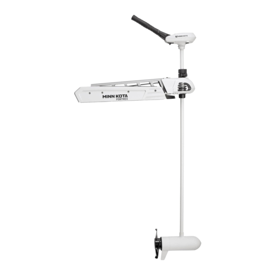
Page 5: Features
FEATURES Tilt/Extend Tiller Controls: On/Off, Speed, Forward/Reverse and Direction Battery Meter Mono-Arm Design Depth Collar Knob BowGuard 360° ® Breakaway Protection Lift-Assist Lifetime Warranty Flexible Composite Shaft Cool Quiet Power Motor Propeller Specifications subject to change without notice. This diagram is for reference only and may differ from your actual motor. minnkotamotors.com | 5 ©2017 Johnson Outdoors Marine Electronics, Inc. -
Page 6: Mount Installation
MOUNT INSTALLATION TOOLS AND RESOURCES REQUIRED: • Phillips Screw Driver • 1/4” Allen Wrench • Drill • 9/32” Drill Bit • 7/16” Box End Wrench • A second person to help with the installation ASSEMBLY OF MOTOR TO MOUNT 1. Place the mount on an elevated surface such as a workbench or tailgate of pickup. 2. - Page 7 MOUNT INSTALLATION INSTALLATION OF THE BOW-MOUNT We recommend that you have another person help with this procedure. 1. For installation, DO NOT REMOVE THE SHAFT/MOTOR FROM THE BOWGUARD. The Bowguard spring is under tension and must always remain secured. 2. Place the mount, with the motor in the fully stowed (fl at) position, on the deck of the boat: •...
- Page 8 MOUNT INSTALLATION INSTALLING THE BOWMOUNT STABILIZER 1. Place motor in the stowed position. 2. Unthread the composite rod from the bracket and attach bracket to the bottom of the Bowguard using the 5/16” cap screws and nuts. The nuts fi t into pocket on the inside of the Bowguard behind the spring. NOTE: The bracket can be installed on the left or right side of the Bowguard.
- Page 9 MOUNT INSTALLATION REMOVAL OF THE BOWGUARD WARNING: The gas assist lift mechanism in this unit is under HIGH SPRING PRESSURE when the motor is in the deployed position. DO NOT remove the Bowguard assembly from the mount without disconnecting one end of the gas spring. Failure to do this can create a condition where accidental pulling of the rope may cause the mount to spring open rapidly, striking anyone or anything in the direct path.
-
Page 10: Battery & Wiring Installation
CAUTION: These guidelines apply to general rigging to support your Minn Kota motor. Powering multiple motors or additional electrical devices from the same power circuit may impact the recommended conductor gauge and circuit breaker size. If you are using wire longer than that provided with your unit, follow the conductor gauge and circuit breaker sizing table below. -
Page 11: Selecting The Correct Batteries
Breaker Sizing Table” in the previous section to fi nd the appropriate circuit breaker or fuse for your motor. For motors requiring a 60-amp breaker, the Minn Kota MKR-19 60-amp circuit breaker is recommended. CONNECTING THE BATTERIES IN SERIES (IF REQUIRED FOR YOUR MOTOR) -
Page 12: Motor Wiring Diagram
MOTOR WIRING DIAGRAM NOTE: This is a universal, multi-voltage diagram. Double-check your motor's voltage for proper connections. Over-Current Protection Devices not shown in this illustration. BLACK M- SPEED ADJUSTMENT SWITCH BATTERY GAUGE RED B+ BLACK B- BLACK 12V BATT 1 MOTOR 12V BATT 1 12V BATT 2... -
Page 13: Using & Adjusting The Motor
USING AND ADJUSTING THE MOTOR STOWING AND DEPLOYING THE MOTOR WARNING: When raising or lowering the motor, keep fi ngers clear of all hinge and pivot points and all moving parts. MOUNT FEATURES • The motor mount is designed to fold back and lock the motor fl at on the deck when not in use and to provide secure stowage for transport. -
Page 14: Adjusting The Depth Of The Motor
USING & ADJUSTING THE MOTOR ADJUSTING THE DEPTH OF THE MOTOR Quick Release Depth Collar Lever Arm When setting the depth be sure the top of the motor is submerged at least 12” to avoid churning or agitation of surface water. The propeller must be completely Steering Tension Vertical Stow Knob submerged. -
Page 15: Adjusting The Tilt/Extend Tiller
USING & ADJUSTING THE MOTOR ADJUSTING THE TILT/EXTEND TILLER Your trolling motor features 7 usable handle tilt positions: 45°, 30°, and 15° up and down from the 0° (horizontal) position. To use the down positions, you must fi rst press the release button located on the left underside of the pivot handle. -
Page 16: Service & Maintenance
SERVICE & MAINTENANCE PROPELLER REPLACEMENT Propeller TOOLS AND RESOURCES REQUIRED: • Box End Wrench - 1/2” for motors with 70 lbs thrust or lower. - 9/16” for motors with 80 lbs thrust or higher. • Screwdriver (optional) Anode/Nut Washer CAUTION: Disconnect the motor from the battery before beginning any prop work or maintenance. -
Page 17: Troubleshooting & Repair
AUTHORIZED SERVICE CENTERS Minn Kota has over 300 authorized service centers in the United States and Canada where you can purchase parts or get your products repaired. Please visit our Authorized Service Center page on our website to locate a service center in your area. -
Page 18: Environmental Compliance Statements
Minn Kota motors are not subject to the disposal regulations EAG-VO (electric devices directive) that implements the WEEE directive. Nevertheless never dispose of your Minn Kota motor in a garbage bin but at the proper place of collection of your local town council. -
Page 19: Parts Diagram
RIPTIDE FORTREX 112 112 LBS THRUST - 36 VOLT - 62” SHAFT This page provides Minn Kota® WEEE compliance disassembly instructions. For more information about where you should dispose of your waste equipment for recycling and recovery and/or your European Union member state require- ments, please contact your dealer or distributor from which your product was purchased. -
Page 20: Parts List
PARTS LIST RIPTIDE FORTREX 112 112 LBS THRUST - 36 VOLT - 62” SHAFT PART PART ITEM DESCRIPTION ITEM DESCRIPTION NUMBER NUMBER 2317091 36V MOTOR 62” SW 2333101 NUT, 10-24, NYLOCK, SS 2-100-245 ARMATURE ASSEMBLY 2991521 CAM LOCK/DEPTH COLLAR ASSY... - Page 21 PARTS LIST RIPTIDE FORTREX 112 112 LBS THRUST - 36 VOLT - 62” SHAFT PART PART ITEM DESCRIPTION ITEM DESCRIPTION NUMBER NUMBER 2281702 WASHER, LOCK 1/4 2286700 PLUG, SPACER 2284212 OUTER ARM, LONG, 62” 2283900 RAMP, MOTOR 2992302 ROPE GUIDE ASSEMBLY 2283631 RAIL, MACH., MOTOR REST...
- Page 22 Stop buying new batteries and start taking care of the ones you’ve got. Many chargers can actually damage your battery over time – creating shorter run times and shorter overall life. Digitally controlled Minn Kota chargers are designed to provide the fastest charge that protect and extend battery life.
- Page 23 RIPTIDE FORTREX ® ® MOTEUR DE PÊCHE À LA TRAÎNE MONTÉ SUR L’ÉTRAVE MANUEL DE L’UTILISATEUR...
- Page 24 REMARQUE : ne pas retourner le moteur Minn Kota au détaillant. Le détaillant n’est pas autorisé à réparer ou à remplacer cet appareil. Pour le service communiquer avec Minn Kota au +1 (800) 227-6433; retourner le moteur au Centre de service de l’usine de Minn Kota; envoyer ou apporter le moteur à...
- Page 25 TABLE DES MATIÈRES Garantie Limitée de Deux Ans Caractéristiques Installation du Support 28-31 Installation de la Batterie et du Câblage 32-33 Gréement de l’embarcation et Installation du Produit Tableau des Dimensions de Gabarit des Conducteurs et Disjoncteurs Gabarit « Poussoir d’essai » de la batterie Sélectionner une Batterie Adéquate Comment raccorder la Batterie Schéma de Câblage du Moteur...
-
Page 26: Garantie Limitée De Deux Ans
Les articles achetés à l’extérieur des États-Unis doivent être retournés, port payé avec la preuve d’achat (y compris la date d’achat et le numéro de série), à tout centre de service agréé Minn Kota dans le pays de l’achat. Le service au titre de la garantie peut être obtenu en communiquant avec le centre de service agréé... -
Page 27: Caractéristiques
CARACTÉRISTIQUES La poignée d’inclinaison/d’extension contrôle la fonction marche/arrêt, la vitesse, la marche avant/arrière et la direction Jauge de Batterie Conception Mono-Bras Bouton du Collier de Profondeur Protection BowGuard 360° ® Mécanisme de levage assisté Arbre compositeFlexible Garanti à Vie Moteur Cool Power Silencieux Hélice Les spécifications sont sujettes à... -
Page 28: Installation Du Support
INSTALLATION DU SUPPORT OUTILS ET RESSOURCES NÉCESSAIRES: • Tournevis Phillips • Clé Allen de 6,35 mm (1/4”) • Perceuse • Mèche de 7,144 mm (9/32”) • Clé à oeil de 11 mm (7/16”) • Une deuxième personne pour vous aider avec l’installation ASSEMBLAGE DU MOTEUR AU MONTANT 1. - Page 29 INSTALLATION DU SUPPORT MONTAGE SUR LA PROUE Il est recommandé de se faire assister pour cette procédure. 1. Pour la pose, ne séparez pas l’arbre/moteur du garde-proue Bowguard. Le ressort du garde-proue est sous tension et doit toujours rester assuré. 2.
- Page 30 INSTALLATION DU SUPPORT INSTALLER LE STABILISATEUR DU MONTANT DE PROUE (SI COMPRIS) 1. Placez le moteur en position rangée. 2. Dévissez la tige de composite du support et fi xez le support au bas du protège proue à l’aide des vis Allen de 7,93 mm (5/16 po) et écrous.
- Page 31 INSTALLATION DU SUPPORT DÉPOSE DU GARDE-PROUE AVERTISSEMENT: Le mécanisme de levage assisté dans cette unité est sous HAUTE PRESSION PAR LE RESSORT quand le moteur est en position déployée. N’ENLEVEZ PAS l’assemblage de garde-proue du montant sans décrocher une extrémité du ressort au pas du gaz.
-
Page 32: Gréement De L'embarcation Et Installation Du Produit
é. Les spécifi cations suivantes sont seulement des lignes directrices générales: MISE EN GARDE!: ces lignes directrices s’appliquent au gréement général pour soutenir le moteur de Minn Kota. L’alimentation de multiples moteurs ou d’autres appareils électriques, à partir du même circuit d’alimentation, peut infl uer sur le gabarit de conducteurs et le dimensionnement des disjoncteurs recommandé. -
Page 33: Sélectionner Une Batterie Adéquate
Si vous utilisez une batterie à manivelle pour démarrer un moteur hors-bord à essence, nous vous recommandons d’utiliser des batteries marines à décharge profonde séparées pour votre propulseur électrique Minn Kota. -
Page 34: Schéma De Câblage Du Moteur
SCHÉMA DE CÂBLAGE DU MOTEUR REMARQUE: Il s’agit d’un schéma multi-tensions universel. Vérifier à nouveau la tension du moteur afin de vous assurer que les raccordements sont appropriés. Les dispositifs de protection contre la surintensité ne figurent pas dans cette illustration. NOIR M- INTERRUPTEUR DE RÉGLAGE... -
Page 35: Utilisation Et Réglage Du Moteur
UTILISATION ET RÉGLAGE DU MOTEUR L’ARRIMAGE ET LE DÉPLOIEMENT DU MOTEUR AVERTISSEMENT! : Lorsque vous remontez ou abaissez le moteur, gardez vos doigts loin de toutes charnières et points de pivot et de toutes pièces mobiles. CARACTÉRISTIQUES DU SUPPORT • Le support Edge est conçu pour se replier et verrouiller le moteur à plat sur le pont, lorsqu’il n’est pas utilisé, et pour fournir un arrimage sûr pour le transport. -
Page 36: Contrôle De Vitesse Et Direction Avec Le Tiller
UTILISATION ET RÉGLAGE DU MOTEUR RÉGLAGE DE LA PROFONDEUR DU MOTEUR Collier de Profondeur Bras de Levier Relâche Rapide Au moment du réglage de la profondeur, s’assurer que le dessus du moteur est immergé à au moins 12 po (30,5 cm) afi n d’éviter de faire tourbillonner ou d’agiter Bouton de Tension RÉGLAGE DE LA PROFONDEUR DU MOTEUR de la Direction... -
Page 37: Réglage De La Barre D'inclinaison/D'extension Tiller
UTILISATION ET RÉGLAGE DU MOTEUR RÉGLAGE DE LA BARRE D’INCLINAISON / D’EXTENSION TILLER Votre moteur de pêche à la traîne dispose d’une poignée permettant 7 positions d’inclinaison: De 45°, 30° et 15° vers le haut et le bas à part de la position (horizontale) de 0°. -
Page 38: Service Et Entretien
SERVICE ET ENTRETIEN REMPLACEMENT DE L’HÉLICE REMPLACEMENT DE L’HÉLICE Hélice OUTILS ET RESSOURCES NÉCESSAIRES: Hélice OUTILS ET RESSOURCES NÉCESSAIRES: • Clé à oeil - 12.5mm pour les moteurs à £ 70 ou moins poussée. • Clé à oeil - 14.2875 mm pour les moteurs à poussée £ 80 ou plus) - 12.5mm pour les moteurs à... -
Page 39: Dépannage Et Réparation
FOIRE AUX QUESTIONS Notre site Web présente FAQ visant à répondre à toutes vos questions au sujet des produits Minn Kota. Veuillez visiter le site Web minnkotamotors.com, puis cliquer sur « Foire aux questions » pour trouver réponse à vos questions. -
Page 40: Déclaration De Conformité
Les moteurs Minn Kota ne sont pas soumis à la réglementation concernant l’élimination VGE-VO (directive pour les dispositifs électriques), qui transpose la directive DEEE. Néanmoins, ne jamais jeter le moteur Minn Kota dans une poubelle, mais plutôt à l’endroit approprié où s’eff ectue la collecte, recommandé par le conseil municipal local. -
Page 41: Schéma Des Pièces
RIPTIDE FORTREX 112 POUSSÉE DE 112 LBS - 36 VOLT - ARBRE 62 PO Cette page fournit les consignes de dépose de Minn Kota® en conformité avec la directive DEEE. Pour de l’information supplémentaire sur l’endroit où vous pou- vez vous débarrasser de l’équipement usagé pour le recyclage et la récupération et/ou sur les exigences de votre État membre de l’Union européenne, veuillez... -
Page 42: Liste Des Pièces
LISTES DES PIÈCES RIPTIDE FORTREX 112 POUSSÉE DE 112 LB - 36 VOLTS - ARBRE 62 PO NUMÉRO NUMÉRO ARTICLE QTÈ DESCRIPTION ARTICLE QTÈ DESCRIPTION DE PIÈCE DE PIÈCE 2317091 MOTEUR 36V 62” FW 2333101 ÉCROU — 10-24, NYLOCK 2-100-245... - Page 43 LISTES DES PIÈCES RIPTIDE FORTREX 112 POUSSÉE DE 112 LB - 36 VOLTS - ARBRE 62 PO NUMÉRO NUMÉRO ARTICLE QTÈ DESCRIPTION ARTICLE QTÈ DESCRIPTION DE PIÈCE DE PIÈCE 2281702 RONDELLE À RESSORT 1/4 2073408 VIS, 1/4-20 X 7/8 (6.3 MM-20 X 1 X 22,2 MM) 2284212 BRAS EXTÉRIEUR...
- Page 44 à la longue, pouvant entraîner une autonomie réduite et une durée de vie plus courte. Les chargeurs Minn Kota à commande numérique assurent une charge rapide pour une protection et une durée de vie prolongée.