
Manuels Connexes pour Chauvin Arnoux C.A 25


Sommaire des Matières pour Chauvin Arnoux C.A 25
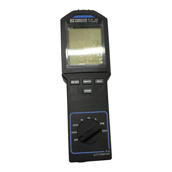
- Page 1 C.A 25 TACHYMETRE TACHOMETER C.A 27 FRANCAIS Mode d'emploi E N G L I S H User's manual...
-
Page 2: Précautions D'emploi
PRÉCAUTIONS D'EMPLOI ! ! ! ! ! En mesure sans contact : Avant d'utiliser le tachymètre, vérifier que la fenêtre frontale de visée soit parfaite- ment propre. La distance de détection minimale est de 1 cm, il faut cependant éviter la proximité immédiate de toute pièce en mouvement qui pourrait être dangereuse pour l'opérateur et pour l'appareil. -
Page 3: Table Des Matières
English version see page 47 ..........................SOMMAIRE Page INTRODUCTION ..........................DESCRIPTION ............................Tachymètre ............................Afficheur ..............................Étiquettes mode d'emploi ..................... UTILISATION ............................Mesures sans contact ......................Mesures avec contact ......................Mesures avec entrée externe ..................FONCTIONNEMENT ........................Choix de l'unité de mesure .................... -
Page 4: Introduction
INTRODUCTION Spécialement conçu pour des applications industrielles, les tachymètres C.A 25 et C.A 27 mesurent à distance, ou par contact, la vitesse de rotation de toute pièce en mouvement. Par leur capteur optique intégré à infrarouges modulés, ces deux modèles offrent l'avantage de pouvoir travailler dans n'importe quelle ambiance lumineuse. - Page 5 11- touche RANGE - changement de gamme manuel ou automatique. - élargissement du domaine de mesure en basse fréquence. 12 - touche MIN MAX - enregistrement des minima et maxima. - inhibition du buzzer. Modèle C.A 27 uniquement 2 - touche - en programmation, déplacement du chiffre ou de la virgule vers la droite 3 - touche - en programmation, incrémentation du chiffre...
-
Page 6: Afficheur
AFFICHEUR (voir dessins en fin de mode d'emploi) Modèles C.A 25 et C.A 27 10 témoin clignotant de fonctionnement du capteur infrarouge. 11 valeur de la fin d'échelle (de 2 à 200 x 1000). 12 affichage analogique par bargraph 42 segments. -
Page 7: Étiquettes Mode D'emploi
Modèle C.A 27 uniquement mode programmation en service. seuil bas franchi. coefficient K de fin d'échelle en programmation ou en service. fonction seuil bas en programmation ou en service. demande d'émission sur sortie RS232 effectuée. fonction seuil haut en programmation ou en service. seuil haut franchi. -
Page 8: Utilisation
UTILISATION MESURES SANS CONTACT La prise de mesure sans contact s'effectue par le capteur optique intégré à l'appareil. Ce capteur placé dans la partie avant de l'appareil, se compose d'un émetteur de lumière infrarouge modulée en fréquence. Le récepteur infrarouge est calé... -
Page 9: Mesures Avec Contact
MESURES AVEC CONTACT L'adaptateur mécanique est un accessoire qui vient se placer devant la fenêtre de visée du capteur optique. Il transforme la mesure optique sans contact en une mesure avec contact sur la pièce en mouvement. Les différents accessoires prévus sont au nombre de trois : - un cône en élastomère dont la pointe finale permet la mesure en bout d'arbre (diamètre minimum : 5 mm). - Page 10 Le raccordement de la broche n°1 à la broche n°3 permet de changer le seuil de déclenchement : - Broches 1 et 3 non connectées. Ce mode de fonctionnement est prévu pour être utilisé avec des signaux à la norme TTL O-5 V ou à...
- Page 11 L'utilisation de l'entrée externe est nécessaire pour la mesure de signaux lents à partir de 0,1 Hz. Le tableau ci-après résume les caractéristiques de cette entrée. GAMME DE FRÉQUENCE de 1Hz à 10 kHz DE MESURE de 0,1 Hz à 10 kHz en gamme élargie FONCTIONS DISPONIBLES Idem capteur optique PRÉCISION...
-
Page 12: Fonctionnement
FONCTIONNEMENT CHOIX DE L'UNITÉ DE MESURE La sélection de l'unité de mesure se fait à l'aide du commutateur rotatif à 8 positions. Position OFF : Arrêt. Position tr/min : mesure de vitesse de rotation en tour par minute (tr/min). Position m/min : mesure de vitesse linéaire en mètre par minute (m/min). Position Hz : mesure de fréquence en Hertz (Hz). - Page 13 Fonction Marche/Arrêt. La position OFF du commutateur rotatif coupe l'alimentation de l'appareil de manière mécanique. En position marche, un système d'économie de pile coupe automatiquement l'alimentation de l'appareil si il n'y a pas eu pendant 5 minutes: - appui sur une touche, - ni manoeuvre du commutateur rotatif, - ni interrogation de la sortie numérique.
-
Page 14: Enregistrement Min/Max
Remarque : toute rotation du commutateur de mesure annule les fonctions enregistrement MIN/MAX (RECORD), lissage (SMOOTH), maintien (HOLD), gamme manuelle (RANGE), comptage (COUNT) et alarmes (LO AL et HI AL). ENREGISTREMENT MIN/MAX Cette fonction n'est accessible qu'en mesure, le symbole PRGM étant éteint sur l'afficheur. -
Page 15: Maintien De La Valeur Numérique À L'affichage
Pendant la lecture, la mémoire continue d'enregistrer les minima et maxima éventuels tandis que le bargraph indique la mesure instantanée. Si pendant l'enregistrement, le symbole SMOOTH est affichée, celui-ci sera fait sur les valeurs de mesures filtrées (voir "LISSAGE DE LA MESURE"). Arrêt de la fonction enregistrement MIN/MAX L'arrêt de la fonction enregistrement est obtenu, soit par un appui sur MIN MAX... - Page 16 Une nouvelle pression sur libère l'enregistrement des MIN et des HOLD MAX : - les symboles HOLD et PAUSE s'éteignent - l'afficheur numérique indique la mesure en cours ou le contenu de la mémoire MIN/MAX en relecture - l'appareil est à nouveau en fonction MIN/MAX mais les mémoires n'ont pas été...
-
Page 17: Lissage De La Mesure
Application : lorsqu'il est nécessaire de positionner le tachymètre dans un endroit où la visualisation est difficile ou impossible, l'utilisation de la fonction HOLD couplée avec l'enregistrement MIN/MAX permet de conserver en mémoire le minimum et maximum atteint. Il est alors plus aisé de déplacer le tachymètre de sa position de mesure pour aller lire les valeurs enregistrées. -
Page 18: Comptage
En mode automatique, l'afficheur numérique passe sur une gamme supérieure quand 20 000 points sont atteints. Une première pression momentanée (<2s) sur bloque le changement RANGE automatique de gamme, pour les deux affichages, sur la gamme de mesure en cours. RANGE apparaît sur l'afficheur. L'indicateur numérique a alors une capacité d'affichage de 100 000 points. -
Page 19: Impression
- en standard, l'appareil compte des mètres ou des pieds ("feet") avec une définition de mesure égale à la circonférence de l'embout utilisé, soit 0,1 m ou 0,328 ft (roue calibrée CHAUVIN ARNOUX). Cette définition peut être modifiée en changeant K. - Page 20 A chaque pression de , l'appareil envoie une série d'informations au PRINT standard RS232 sous la forme < fonction > 3 espaces < mesure > 3 espaces < unité > Chaque groupe est séparé par 3 espaces. La sortie se termine par un retour chariot et deux sauts de ligne.
- Page 21 avec SMOOTH. PRINT La valeur imprimée est alors la valeur lissée, quand cette fonction est engagée (SMOOTH à l'écran). Exemple : SMOOTH 112,32 m/min à la mise en marche du tachymètre. PRINT Si cette touche est enfoncée à la mise en marche de l'appareil, on obtient l'impression des valeurs contenues dans la mémoire programme pour la fonction sélectionnée par le commutateur rotatif.
-
Page 22: Alarmes
ALARMES (C.A 27 uniquement) La fonction "Alarmes" est disponible uniquement en mesure. Lorsque des seuils ont été programmés, la pression de met en service ALARM la détection de franchissement de ces seuils par la mesure. Les symboles , ou les deux, s'allument sur l'afficheur en fonction du type de seuil programmé. -
Page 23: Programmation
PROGRAMMATION (C.A 27 uniquement) L'appareil possède quatre valeurs programmables par l'utilisateur qui permettent de définir : - un seuil d'alarme basse LO AL - un seuil d'alarme haute HI AL - un coefficient multiplicateur K - un intervalle d'impression SCAN Ces quatre valeurs sont programmables séparément, pour chacune des douze unités de mesure disponibles par le commutateur rotatif et la touche COUNT... - Page 24 Mode Opératoire Les explications ci-dessous décrivent la procédure à employer pour programmer les différentes mémoires du C.A 27. Ces étapes sont communes à toutes les fonctions : scanning, seuils, et coefficient K. Les paragraphes "Seuils d'alarmes" à "Intervalle d'impression" décrivent les particularités relatives à...
- Page 25 Exemple : 1. Affichage 2. Touche 3. Affichage Une pression constante sur une touche entraîne une incrémentation ou une décrémentation automatique. Il faut relâcher la touche à l'apparition du chiffre désiré. Si pendant les opérations d'incrémentation ou de décrémentation les capacités maximales de l'afficheur sont dépassées, l'afficheur indiquera à...
- Page 26 Exemple : 1. Affichage 2. Touche 3. Affichage 4. Touche 5. Affichage Lorsque la virgule active est située à l'extrémité gauche ou droite de l'afficheur, toute nouvelle pression sur provoquera l'apparition de "-----". Pour obtenir le retour de la virgule sur l'afficheur, il suffit d'appuyer sur suivant que celle-ci est sortie à...
-
Page 27: Seuils D'alarmes
Le passage du comutateur de "tr/min" sur "OFF" entraîne la perte de la valeur en cours de programmation. Les valeurs précédemment entrées restent en mé- moire. La relecture des informations contenues en mémoire s'effectue de la même manière que la programmation, sauf que les touches ne doivent pas être pressées. - Page 28 Exemples : - Programmation d'un rapport de boite. Ceci permet de visualiser directement la vitesse en sortie d'un réducteur par mesure de la vitesse sur l'entrée. - Mesure de débit. Un débitmètre fournit une impulsion tous les 2 m . En Hz on a directement la mesure du débit (K = 2) par seconde.
-
Page 29: Intervalle D'impression
coefficient K programmé Unités de mesure 0,01 99,999 fréq.Max entrée 9999,9 Hz 1 000 Hz donnant un 99 999 pts 99 999 pts affichage Max de 0,1 Hz 0,1 Hz fréq.Min entrée donnant un 0,0010 pts 9,9999 pts affichage Min de fréq.Max entrée 10 000 Hz 16,666 Hz... -
Page 30: Interrogation À Distance
La valeur programmée fixe le nombre de secondes séparant deux impressions successives. Les limites sont 10 secondes minimum et 99 999 secondes maximum (environ 27 heures). Lorsqu'une valeur a été programmée, le symbole SCAN apparaît sur l'afficheur seulement après appui sur en mode mesure (voir "... - Page 31 Le réveil obtenu par une commande à distance ne remet pas l'émetteur optique en marche, celui-ci doit être commandé séparément par la commande prévue à cet effet. Une action sur durant la transmission des données permet de stopper PRINT cette transmission. Elle ne peut pas démarrer la fonction scanning. Le symbole "COM"...
- Page 32 Une commande d'arrêt envoyée alors que le capteur est déjà arrêté est inopérante. - Interrogation de la mesure Codes à envoyer à l'appareil pour déclencher l'émission de la mesure : - 3 F Hexa, 63 Décimal, graphisme correspondant : ? La réponse à...
- Page 33 Le groupe 1 contient 4 caractères, alignés sur la droite, indiquant les fonctions programmées. Elles seront données dans l'ordre : - LO AL : pour le seuil bas - HI AL pour le seuil haut pour le coefficient multiplicateur - SCAN : pour le nombre de secondes du Scanning Les caractères non utilisés sont remplacés par des espaces.
- Page 34 Pendant l'impression des valeurs contenues dans la mémoire, la manoeuvre du commutateur rotatif ou l'action sur une des touches n'a aucune action sur la sortie des informations. - Interrogation partielle de la mémoire Codes à envoyer pour obtenir la sortie du contenu de la mémoire uniquement dans la fonction sélectionnée pour la mesure : - 23 Hexa, 35 décimal, graphisme correspondant : # La réponse à...
- Page 35 - SEN. si le capteur optique est allumé, OFF si le capteur optique est arrêté, EXT si l'entrée capteur externe est à 0, - BAT. si la pile est bonne, symbole pile éteint sur l'afficheur, OFF si la pile est déchargée, symbole pile allumé sur l'afficheur.
-
Page 36: Exemple D'utilisation
EXEMPLE D'UTILISATION MESURE DE RAPPORT CYCLIQUE SUR ENTRÉE EXTERNE L'utilisation de l'entrée externe nécessite le raccordement du connecteur FRB fourni avec l'appareil à la source du signal à mesurer, puis le branchement de ce connecteur sur la prise marquée EXT. Supposons avoir un signal du type de celui montré... -
Page 37: Programme De Scrutation Sur Ordinateur
= 60 % 3 + 2 Pour effectuer cette mesure avec les tachymètres C.A 25 ou C.A 27, il faut : 1)Vérifier l'amplitude du signal entrant dans l'appareil. Ceci permet de déterminer le seuil à fixer. Ici l'amplitude est supérieure à +1,1 V, donc il ne faut pas raccorder les broches 1 et 3 de la prise FRB entre elles. -
Page 38: Programme De Communication
PROGRAMME DE COMMUNICATION print "**** AFFICHAGE DES MESURES DU TACHYMETRE ****" Open "COM1 : 1200, N, 8, 1, RS" as #1 print #1, chr$(07) 'réveil de l'appareil ... delay 2.5 print #1, chr$(63) 'interrogation de la mesure... carac = 0 : k$ = "" : D = 0 while k$ = ""... -
Page 39: Adaptateurs Et Embouts
ADAPTATEUR ET EMBOUTS L'adaptateur mécanique et ses embouts permettent la mesure par contact en bout d'arbre ou sur surface en mouvement linéaire. Au nombre de 3, ces embouts se fixent sur un mécanisme commun : l'adaptateur mécanique. L'adaptateur et les embouts ne sont pas fournis avec le tachymètre. CARACTÉRISTIQUES - Embout cônique Il permet la mesure par contact en bout d'axe évidé... -
Page 40: Fixation
FIXATION L'adaptateur se fixe sur l'avant du boitier du tachymètre à l'aide de 3 pattes type 1/ 4 de tour. Un verrouillage en fin de course assure le maintien en position (système à baïonette). - Montage Pour fixer l'adaptateur, il suffit de glisser ses trois ergots derrière ceux du boitier par un mouvement de rotation dans le sens inverse des aiguilles d'une montre. -
Page 41: Entretien
ENTRETIEN Le tachymètre ne réclame aucun entretien particulier, hormis le remplacement de la pile et le nettoyage du boitier. - réglages L'appareil ne possède aucun réglage interne. La précision de mesure est donnée par un quartz de grande stabilité qui pilote le microprocesseur. - nettoyage du boitier Le nettoyage du boitier peut être effectué... -
Page 42: Caractéristiques
CARACTÉRISTIQUES CARACTÉRISTIQUES GÉNÉRALES Appareil : tachymètre à capteur optique, entrée externe et entrée/sortie RS232 (C.A 27 uniquement) Fonctions : mesures de tr/min, m/min, Hz, ms et rapport cyclique Boitier : polycarbonate, lentille capteur en méthacrylate Dimensions : 216 x 72 x 47 mm Masse : environ 250 g. -
Page 43: Métrologiques
CARACTÉRISTIQUES MÉTROLOGIQUES - Conditions de références Grandeur d'influence Condition de référence Tolérances Température ambiante + 22°C ± 2°C Humidité relative 65 % ± 5 % Champ magnétique ext. < 40 A/m à 50 ou 60 Hz Champ électrique < 1 V/m à 50 ou 60 Hz Tension pile ±... - Page 44 - Fonction Hz. Pour des fréquences supérieures à 10 kHz (limite supérieure du domaine d'utilisa- tion) l'appareil peut indiquer des valeurs erronnées. Calibre * 0,1000 10,000 100,00 1000,0 9,9999 99,999 999,99 9999,9 résolution 0,0004 Hz 0,004 Hz 0,04 Hz 0,4 Hz précision 4.10 de la lecture ±...
- Page 45 - Fonction périodemètre Calibre * 9999,9 999,99 99,999 9,9999 1000,0 100,00 10,000 0,1000 résolution 0,3 ms 0,03 ms 0,003 ms 0,0005 ms précision 1.10 de la lecture ± 5 points temps de 11s>t>1,5s 1,5s>t>0,5s <0,5s mesure stabilité ± 1 résolution * de 1000,0 à...
-
Page 46: Capteurs
- Fonction compteur d'évènements Gamme de mesure de 0 à 99 999 évènements de 1 Hz à 10 kHz Gamme de fréquence de comptage de 0,1 Hz à 10 kHz avec l'entrée extérieure en gamme élargie Précision du comptage ± 1 évènement CARACTÉRISTIQUES DES CAPTEURS Conditions de mesure Capteur optique... - Page 47 - capteur optique Longueur d'onde d'émission : 890 nm. Puissance lumineuse d'émission : dépend de la distance de visée, à 1 cm : ~ 0,5 mW/cm à 50 cm : ~ 2 mW/cm Puissance lumineuse minimale en réception : 10 µW/cm Rapport surface réfléchissante/surface cible : >...
-
Page 48: Pour Commander
Accessoires du C.A 25 KIT ACCESSOIRES MECANIQUES P01.1749.02 ................. composé de 1 adaptateur mécanique, 1 roue calibrée, 1 embout conique, 1 embout cylindrique et 1 boîte d'emballage CHAUVIN ARNOUX. GAINE ANTICHOC P01.2980.09A ..........................Rechanges du C.A 25 EMBOUTS (jeu de 3) P01.1749.03... -
Page 49: Annexe : Fonctionnement De La Liaison Rs 232
ANNEXE : fonctionnement de la liaison RS 232 La sortie RS 232 est une interface bi-directionnelle qui permet à l'appareil de communiquer avec des périphériques extérieurs. Les signaux de transmission des informations sont à la norme RS 232 C dont l'amplitude est comprise entre +/- 5 V et +/- 15 V. - Page 50 English...
-
Page 51: Safety Precautions
SAFETY PRECAUTIONS For measurement without contact : Before using the tachometer check that the front sighting window is perfectly clean. The minimum detection distance is 1 cm, nevertheless avoid immediate proximity of any moving part which could be dangerous for the user or the instrument. For measurement with contact : Keep your hands as far as possible from the moving part. - Page 52 CONTENTS Page INTRODUCTION ..........................DESCRIPTION ............................Tachometer ............................Display ..............................Operator's manual labels ...................... OPERATION ............................Measurements without contact ..................Measurements with contact ....................Measurements with external input ................HOW TO USE ............................Choice of the measurement function ................. MIN/MAX recording ........................
-
Page 53: Introduction
INTRODUCTION Specially designed for industrial applications, the C.A 25 and C.A 27 tachymeters measure at a distance, or by contact, the rotational speed of any moving part. With their integrated modulated infrared optical sensor both these models have the advantage of being able to work in any lighting conditions. - Page 54 RANGE button - manual or automatic range change. - extension of the measurement range to low frequency. button MIN MAX - records min and max. - suppresses buzzer. Model C.A 27 only button - when programming, more the digit or the decimal point to the right button - when programming, increase of the digit button...
-
Page 55: Display
DISPLAY (see drawing at the end of the user's manual) Models C.A 25 and C.A 27 10 Flashing indicator showing sensor operation 11 End of scale value (from 2 to 200 x 1000) 12 Analogue display by 42 segment bargraph 13 Arrow symbolising over-ranging end of scale 14 R.P.M.: rotational speed... -
Page 56: Operator's Manual Labels
Model C.A 27 only Programming mode operational Low threshold exceeded Programming end of scale K coefficient Programming low threshold function RS 232 output request made Programmable high threshold function High threshold exceeded Programming printing rate function RS 232 output or input functioning 15 Revolutions: rev counter 30 Instrument is counting events OPERATOR'S MANUAL LABELS... -
Page 57: Operation
OPERATION MEASUREMENTS WITHOUT CONTACT Measurements that are taken without contact are done with the optical sensor integrated in the instrument. This sensor, located in the front end of the instrument, consists of a frequency modulated infrared light emitter. The infrared receiver is set at the same modulation frequency. -
Page 58: Measurements With Contact
MEASUREMENTS WITH CONTACT The mechanical adaptor is an accessory which is placed in front of the sighting window of the optical sensor. It transforms the optical measurement without contact into a measurement with contact on the moving part. There are three different accessories available : - a rubber cone with a tip allowing measurements at the end of shafts on axles down to 5 mm diameter. - Page 59 Connection of pin n°1 to pin n°3 makes it possible to change the tripping threshold. - Pins 1 and 3 not connected. This operating mode is designed to be used with standard TTL 0-5 V signals or single polarity signals. The trip threshold is set at + 1.1 V (at 1 kHz). To avoid problems due to noise which is often present in industrial locations, the threshold has a hysteresis of 250 mV.
- Page 60 The use of the external input is necessary for the measurement of slow signals from 0.1 Hz. The table below summarizes the specifications of this input. MEASUREMENT FREQUENCY from 1Hz to 10 kHz RANGE from 0.1 Hz to 10 kHz on extended range FUNCTIONS AVAILABLE Idem optical sensor ACCURACY...
-
Page 61: How To Use
HOW TO USE CHOICE OF THE MEASUREMENT FUNCTION The selection of the measurement function is done with the 8 position rotary switch. OFF position: Off Rpm position: Measurement of rotational speed in revs per minute (rpm) M/min position: Measurement of the linear speed in metres per minute (m/min) Hz position: Measurement of frequency in Hertz (Hz) ms position: Measurements of periodicity in milliseconds (ms) % position: Measurement of the duty in %... - Page 62 On/off function. The OFF position of the rotary switch cuts off the power supply to the instrument mechanically. In the ON position, a battery economy system cuts off the power supply automatically after 5 minutes when none of the following conditions apply: - pressing a button - operation of the rotary switch - reading the digital output...
-
Page 63: Min/Max Recording
Note: Any rotation of the measurement switch cancels the MIN/MAX (RECORD), SMOOTH, HOLD, RANGE, COUNT and LO AL and HI AL alarm functions. MIN/MAX RECORDING This function is only accessible during measurement, the PRGM symbol not being visible on the display. The recording function allows the memorisation of the minimum and maximum values of the measurements. -
Page 64: Hold Display
If during the recording the SMOOTH symbol is displayed, the recording applies to the filtered measurement values (see ch. "SMOOTH MEASUREMENT"). Switching off the MIN/MAX record function The MIN/MAX function is switched off either by pressing the button for MIN MAX more than 2 seconds, or by turning the rotary switch. - Page 65 - The instrument is again on the MIN/MAX function but the memories are not reinitialised and they contain the MIN and MAX values present before HOLD When the HOLD and RECORD-PAUSE symbols are displayed, it is still possible to display, in a circular manner, the values of the memories and the instantaneous measurement by short presses on MIN MAX Displayed value...
-
Page 66: Smoothing The Measurement
SMOOTHING THE MEASUREMENT This function is only available during measurement, PRGM not visible on the display. One press on the button activates smoothing of the measurement SMOOTH (SMOOTH is displayed). The digital value indicated is then the result of a sliding average calculated from 10 measurements (approx. -
Page 67: Counting
Each new press on increases the two displays (analogue and digi- RANGE tal) to the next range up. At the highest range (200,000) resets the RANGE instrument to range 2. To exit manual range operation, press for more than 2 seconds. RANGE Notes: - If the value of the measurement is higher than the selected range, the digital... -
Page 68: Printing
The symbols Hz, ms and % disappear. There are no more units; the instrument simply counts the number of pulses received. Press to block counting. A second press restarts the counting that HOLD was blocked. When it reaches 99999 events, the display changes to OL. To exit counting, presss a second time. - Page 69 with HOLD PRINT The printout will be the value of the digital display, preceded by HOLD. Example: HOLD 215.50 rpm with MIN/MAX recording. PRINT When the instrument is on record mode, RECORD, MIN or MAX on the screen, the printout indicates, in this order, the Min value, the Max value and the current measurement.
-
Page 70: Alarms
Whilst the printout data is being emitted, the PRINT and COM symbols are visible on the display. When the Scanning function is programmed (see programming in "Printing interval"), pressing the button starts the measurement PRINT printing cycle with the programmed interval. The SCAN symbol lights and remains lit throughout the scanning operation. -
Page 71: Programming
If no threshold value has been programmed, a 4 kHz beep is emitted when is pressed and this control is not taken into account. ALARM ALARM To stop the alarm function press again when the indica- tors are lit. PROGRAMMING (C.A 27 only) The instrument has four values that can be programmed by the user which define : - a low alarm threshold LO AL - a high alarm threshold HI AL... - Page 72 Programming function Measurement function buttons buttons shift to left MIN MAX shift to right HOLD Increase digit SMOOTH Decrease digit RANGE SCAN Programme scanning PRINT Programme thresholds ALARM ALARM Programme k coefficient COUNT Operating mode The explanations below describe the procedure to be used to programme the different memories of the C.A 27.
- Page 73 Input a value into the memory as follows : A/ Write all the digits comprising the required value, without taking into account the decimal point. B/ Position the decimal point. A/ Writing a number without a decimal point As soon as one of the arrows on the keyboard is pressed the 5 hyphens change into 5 zeros.
- Page 74 B/ Positioning the decimal point In addition to the 5 digits, the display has a decimal point which can take the five following positions : .-.-.-.-.-. When using this function and when there is no programmed value, the decimal point furthest to the left is lit. To move the displayed decimal point to the right, press until the last digit on the right flashes.
-
Page 75: Alarm Thresholds
When only one value, or the cancelling symbols have been chosen, the validation is done : - either by pressing . Exit the programming mode and PRGM PRGM disappears from the display. - or by changing to another programming function using ALARM SCAN - or by turning the rotary switch to another measurement function, except OFF. - Page 76 Example: When counting objects on pallets, each pulse recorded corresponds to the passage of a pallet of 15 objects. To obtain a direct reading of the number of objects counted, it is first necessary to set K to 15, then select the count function by pressing COUNT This can be done on the "Hz"...
-
Page 77: Printing Interval
Coefficient Programmed K Measurement units 0.01 99.999 Max F input 9999.9 Hz 1 000 Hz giving a Max 99 999 counts 99 999 counts display of 0.1 Hz 0.1 Hz Min F input giving a Min 0.0010 pts 9.9999 pts display of Max F input 10 000 Hz... -
Page 78: Remote Reading
The value programmed sets the number of seconds separating two successive printouts, the limits are 10s minimum and 99999 seconds maximum (approx 27 hours). When the scanning function is ON, the SCAN symbol appears on the display after is pressed on measurement mode (see paragraph 4.7). PRINT If the printout interval exceeds five minutes, the optical emitter of the instrument is switched off between each measurement (... - Page 79 The wake up obtained by a remote control does not switch on the optical emitter, it must be switched separately by the control provided for this purpose. Pressing during the transmission of date will stop this transmission. PRINT It cannot start the SCANNING function. The "COM"...
- Page 80 - Measurement read instruction Codes to send to the instrument to start the measurement emission: - 3 F Hexa, 63 decimal, corresponding graphic: ? The response to this instruction is the emission by the instrument, on the TxD output, of the codes corresponding to the results of the measurements present at the moment when the instruction is sent.
- Page 81 Group 1 contains 4 characters, aligned on the right, indicating the programmed functions. They are given in the order : - LO AL : for the low threshold - HI AL : for the high threshold : for the multiplying coefficient - SCAN : for the number of seconds of the scan The characters that are not used are replaced by spaces.
- Page 82 - Partial readout of the memory Codes to send to output the memory contents only in the measurement function selected: - 23 Hexa, 35 decimal, corresponding graphic: # The response to this road instruction is identical to the preceding output but only systematically supplies 4 lines for the values corresponding to the measurement function that the instrument is in when the enquiry is made.
- Page 83 - BAT if the battery is good, battery symbol not visible on the display. OFF if the battery is discharged, battery symbol visi ble on the display. Note : the use of the TACHOGRAPH makes it possible to free the user from the remote read instruction.
-
Page 84: Example Of Use
EXAMPLE OF USE MEASUREMENT OF DUTY % ON AN EXTERNAL INPUT The use of the external input requires the connection of the FRB connector supplied with the instrument at the source of the signal to be measured, then the connection of this connector to the socket marked EXT. -
Page 85: Scanning Programme On Computer
Duty % = x100 = 60 % To make this measurement with the C.A 25 or C.A 27 tachymeters, you must : 1) Check the amplitude of the signal input at the instrument. This makes it possible to determine the threshold to be set. - Page 86 COMMUNICATION PROGRAM print "**** DISPLAY OF THE TACHOMETER MEASUREMENTS ****" Open "COM1:1200,N,8,1,RS" as #1 print #1,chr$(07) ' wakes up the instrument... delay 2.5 print #1,chr$(63) ' reads the measurement... carac = 0 : k$ = "" : D = 0 while k$ = ""...
-
Page 87: The Mechanical Adaptors
THE MECHANICAL ADAPTORS The mechanical sensors allow measurement by contact at the end of a shaft or on a linear moving surface. There are three of them and they all fit to the same mechanism. These mechanical sensors and their adaptor are not supplied with the tachometer. SPECIFICATIONS - Pointed tip Enables measurement by contact at the end of an axle hollowed out to receive it... -
Page 88: Mounting
MOUNTING The adaptor is mounted on the front of the tachometer case using 3 ¼ turn type lugs. It locks when it is pushed home to ensure that it holds in position. - Fitting To attach the adaptor, simply slide its three lugs behind those of the case with an anti-clockwise rotational movement. -
Page 89: Maintenance
MAINTENANCE The tachometer does not require any particular cleaning, except for replacing the battery and cleaning the case. - adjustments There is no internal adjustment to the instrument. The accuracy of the measurement is given by a high stability quartz which drives the microprocessor. - cleaning the case The case can be cleaned with any non-abrasive, non acid cleaning agent such as alcohol, flugene, etc... -
Page 90: Specifications
SPECIFICATIONS GENERAL SPECIFICATIONS - Instrument : tachometer with optical sensor, external input and RS 232 input/ output (C.A 27 only) - Functions : measurements of rpm, m/min, Hz, ms and duty %. - Case : polycarbonate, sensor lens of methacrylate - Dimensions : 216 x 72 x 47 mm - Weight : approx 250 g - Watertightness : IP54 in accordance with IEC 529... -
Page 91: Metrological Specifications
METROLOGICAL SPECIFICATIONS - reference conditions Distortion magnitude Reference condition Tolerances Ambient temperature + 22°C ± 2 C Relative humidity 65 % ± 5 % External magnetic field < 40 A / m at 50 or 60 Hz Electrical field < 1 V / m at 50 or 60 Hz Battery voltage ±... -
Page 92: Sensors
- Hz Function. For frequencies greater than 10 kHz (upper limit of operating range) the instrument may indicate incorrect values. Range * 0.1000 10.000 100.00 1000.0 9.9999 99.999 999.99 9999.9 resolution 0.0004 Hz 0.004 Hz 0.04 Hz 0.4 Hz accuracy 4.10 of the reading ±... - Page 93 Periodicity function Range * 9999.9 999.99 99.999 9.9999 .99999 1000.0 100.00 10.000 1.0000 .10000 resolution 0.3 ms 0.03 ms 0.003 ms 0.0005 ms 0.00005 ms accuracy 1.10 of the reading ± 5 counts measurement 11s>t>1.5s 1.5s>t>0.5s <0.5s time stability ± 1 resolution * from 1000.0 to 9999.9 ms : only usable with external input.
- Page 94 - Event counter function Measurement range from 0 to 99 999 events from 1 Hz to 10 k Hz Frequency counting range from 0.1 Hz to 10 k Hz with the external input on the extended range counting accuracy ± 1 event SPECIFICATIONS OF THE SENSORS Measurement conditions - optical sensor...
- Page 95 - optical sensor Length of wave emitted : 890 nm. Power of light emitted : Depends on the distance sighted. at 1 cm: 0.5 mw/cm² at 50 cm: 2 mw/cm² Minimum power of light received : 10 µW/cm² Ratio of reflective surface/target surface : > 5 % Detection distance : from 1 to 50 cm Sighting angle in relation to the perpendicular of the target : 0°...
-
Page 96: To Order
Accessories of the C.A 25 KIT OF MECHANICAL ACCESSORIES P01.1749.02 ............... consisting of 1 adaptor tip, 1 calibrated wheel, 1 adaptor cone, 1 adaptor tube and 1 CHAUVIN ARNOUX packaging carton SHOCKPROOF CASE P01.2980.09A ........................Spares for the C.A 25 ADAPTORS (set of 3) P01.1749.03... -
Page 97: Appendix : Description Of The Rs 232 Link
APPENDIX : Operation of the RS 232 The RS 232 output is a bi-directional interface which allows the instrument to communicate with external peripherals. The transmission signals of the data are at the RS 232 C standard which has an amplitude between ±... - Page 98 TACHOMETER C.A 25 Remarque : les numéros absents sont réservés au TACHOMETER C.A 27. Note : the missing numbers refer to the TACHOMETER C.A 27. Voir description page 1 See description page 50 27 26 25 24 23...
- Page 99 TACHOMETER C.A 27 5 6 7 Voir description page 1 See description page 50 27 26 25 24 23...
- Page 100 06-96 Code 906 900 421 - Ed.3 Austria : CA Ges.m.b.H - Slamastraβe 29 / 3 - 1230 Wien - Tel : (1) 61 61 9 61 - Fax : (1) 61 61 9 61 61 Deutschland : CA GmbH - Honsellstraβe 8 - 77694 Kehl / Rhein - Tel : (07851) 50 52 - Fax : (07851) 7 52 90 Espana : CA Iberica - C/Roger de Flor N°...