Publicité
Les langues disponibles
Les langues disponibles
Liens rapides
„ DÉTECTEUR DE TENSION
„ VOLTAGE DETECTOR
„ SPANNUNGSPRÜFER
„ RIVELATORE DI TENSIONE
„ DETECTOR DE TENSIÓN
Notice de fonctionnement
FRANÇAIS
User's manual
E N G L I S H
Bedienungsanleitung
DEUTSCH
Manuale d'uso
ITALIANO
Manual de instrucciones
ESPAÑOL
C.A 771
C.A 771 IP2X
CHAUVIN ARNOUX GROUP
®
Publicité

Manuels Connexes pour Chauvin Arnoux AEMC Instruments C.A 771 IP2X


Sommaire des Matières pour Chauvin Arnoux AEMC Instruments C.A 771 IP2X
- Page 1 „ VOLTAGE DETECTOR C.A 771 IP2X „ SPANNUNGSPRÜFER „ RIVELATORE DI TENSIONE „ DETECTOR DE TENSIÓN ® Notice de fonctionnement FRANÇAIS CHAUVIN ARNOUX GROUP User's manual E N G L I S H Bedienungsanleitung DEUTSCH Manuale d’uso ITALIANO Manual de instrucciones...
- Page 2 English ................22 Deutsch ................. 42 Italiano ................62 Español ................. 82 Vous venez d’acquérir un détecteur de tension C.A 771 ou C.A 771 IP2X et nous vous remercions de votre confiance. Pour obtenir le meilleur service de votre appareil : „...
- Page 3 PRÉCAUTIONS D’EMPLOI Cet appareil est protégé contre des tensions n’excédant pas 1000 V par rapport à la terre en catégorie de mesure IV. La protection assurée par l’appareil peut-être compromise si celui-ci est utilisé de façon non spécifiée par le constructeur et mettre ainsi l’utilisateur en danger. „...
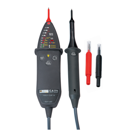
- Page 4 1. PRÉSENTATION 1.1. C.A 771 Pointe de touche Pointe de noire L1. touche rouge. Éclairage Capuchon. du point de mesure. Bargraphe. 1400 Indicateur de 1000 phase. Indicateur de tension 100Ω dangereuse. 2kΩ 60kΩ 300kΩ L1-L2-L3 Indicateur L1-L3-L2 de polarité. Ordre des 30mA Ω...
- Page 5 1.2. AU DOS La pointe de touche noire peut se fixer au dos de l’appareil de deux manières possible : „ à plat, et l’entraxe des pointes de touche est de 16 mm, „ sur le côté, et l’entraxe des pointes de touche est de 19 mm. 16 mm 19 mm Pointe de touche...
- Page 6 1.3. POINTES DE TOUCHE Les bouts des pointes de touche peuvent se retirer. 1400 1000 100Ω 2kΩ 60kΩ 300kΩ L1-L2-L3 L1-L3-L2 30mA AUTO TEST 1.4. C.A 771 IP2X 30mA Voir le § 2.8. 1.5. FONCTIONNALITÉS Le C.A 771 est un Détecteur De Tension (DDT) à voyants. Il est conforme aux prescriptions de la norme IEC 61243-3.
- Page 7 2. UTILISATION Cet appareil est un détecteur. Les indications qu’il fournit ne doivent pas être utili- sées à des fins de mesure. 2.1. AUTO TEST Avant d’utiliser le C.A 771, procédez à un autotest. Il permet de vérifier l’intégrité du cordon et des pointes de touche, le bon fonctionnement du circuit électronique et un niveau de tension suffisant pour les piles.
- Page 8 „ Si un voyant sur trois s’éteint, c’est qu’il y a un problème au niveau des pointes de touche. Vérifiez qu’elles sont correctement branchées et qu’elles sont bien en contact et appuyez à nouveau sur le bouton AUTO TEST. Si le problème persiste, les pointes de touche doivent être remplacées.
- Page 9 2.3. DÉTECTION DE TENSION Connectez la pointe de touche rouge sur la borne + et la pointe de touche noire sur la borne L1. Placez vos mains derrière la garde de l’appareil et de la pointe de touche. Position limite des mains. Placez les pointes de touche sur l’élément à...
- Page 10 Les deux premiers voyants du bargraphe sont verts pour indiquer que la tension n’est pas dangereuse et l’appareil n’émet pas de bip. Les suivants sont rouges et l’appareil émet des bips. Si le voyant ELV s’allume seul, les piles sont usées ou absentes. 1400 1000 100Ω...
- Page 11 „ Comprise entre 100 W et 2 kW : ce sont les 4 premiers voyants du bargraphe qui clignotent. „ Comprise entre 2 kW et 60 kW : ce sont les 3 premiers voyants du bargraphe qui clignotent. „ Comprise entre 60 kW et 300 kW : ce sont les 2 premiers voyants du bargraphe qui s’allument.
- Page 12 „ Si la tension est inférieure à 50 V ou continue, la mesure n’est pas possible. „ Sinon, les deux voyants L1-L2-L3 et L1-L3-L2 clignotent alternativement. 1400 1000 100Ω 2kΩ 60kΩ 300kΩ L1-L2-L3 L1-L3-L2 Lorsque le C.A 771 émet deux bips aigus, déplacez la pointe de touche rouge sur la dernière phase du système.
- Page 13 Une indication de tension apparaît. Appuyez simultanément sur les deux touches , celle de l’appareil et celle de la 30mA pointe de touche. 30 mA Si la tension mesurée est comprise entre 8 Veff et 400 Veff, le test est déclenché. Si la tension est de 230 Veff, le différentiel 30 mA déclenche et l’indication de tension disparaît du bargraphe.
- Page 14 Pointes de touche IP2X 1400 1000 100Ω 2kΩ 60kΩ 300kΩ L1-L2-L3 L1-L3-L2 30mA Ω AUTO TEST 30mA C.A 771 SAFETY TESTER Pour effectuer un test, placez la pointe sur l’objet à tester et appuyez pour faire coulisser la protection.
- Page 15 3. CARACTÉRISTIQUES 3.1. CONDITIONS DE RÉFÉRENCE Grandeur d’influenc Valeurs de référence Température 23 ± 5 °C Humidité relative 30 à 75 % HR Tension d’alimentation 3 ± 0,1 V Fréquence du signal mesuré DC ou 45 à 65 Hz Type de signal sinusoïdal Champ électrique extérieur <...
- Page 16 3.2.4. ORDRE DES PHASES Fréquence comprise entre 45 et 400 Hz. Tension comprise entre 50 et 1000 V entre phases. Temps d’acquisition des informations après contact ≤ 1 s. Temps de rétention de l’information : 10 s. Taux de déséquilibre admissible en amplitude : 20%. Taux d’harmoniques admissible en tension : 10%.
- Page 17 3.4. ALIMENTATION L’alimentation du C.A 771 est réalisée par deux piles 1,5 V alcaline (type AA ou LR6). L’autonomie est de 5 000 mesures de 10 secondes. Les piles peuvent être remplacées par des accumulateurs rechargeables, mais l’autonomie sera bien moindre. 3.5.
- Page 18 4.4. RÉPARATION Pour les réparations sous garantie et hors garantie, contactez votre agence commer- ciale Chauvin Arnoux la plus proche ou votre centre technique régional Manumesure qui établira un dossier de retour et vous communiquera la procédure à suivre. Coordonnées disponibles sur notre site :...
- Page 19 01 44 85 44 85 (Chauvin Arnoux). Pour les réparations hors de France métropolitaine, sous garantie et hors garantie, retournez l’appareil à votre agence Chauvin Arnoux locale ou à votre distributeur. 5. GARANTIE Notre garantie s’exerce, sauf stipulation expresse, pendant douze mois après la date de mise à...
- Page 20 6. POUR COMMANDER Détecteur de tension C.A 771 ............P01191771 Livré avec : „ une pointe de touche rouge Ø 2 mm, „ une pointe de touche noire Ø 2 mm, „ un capuchon de protection pour les pointes de touche, „...
- Page 21 Pointe de touche rouge IP2X Ø 2 mm (une rouge et une noire) ..P01102127Z Pointes de touche rouge IP2X Ø 4 mm (une rouge et une noire) ..P01102128Z Capuchon ................... P01102126Z 6.2. OPTIONS Sacoche de transport ................P01298076...
- Page 22 ENGLISH Thank you for purchasing a C.A 771 or C.A 771 IP2X voltage detector. For best results from your instrument: „ read these operating instructions carefully, „ comply with the precautions for use. WARNING, risk of DANGER! The operator must refer to these instruc- tions whenever this danger symbol appears.
- Page 23 PRECAUTIONS FOR USE This device is protected against voltages up to 1000V with respect to earth in meas- urement category IV. The protection provided by the device may be compromised if it is used other than as specified by the manufacturer and so endanger the user. „...
- Page 24 1. INTRODUCTION 1.1. C.A 771 Black test Red test probe L1. probe. Lighting of Cap. measure- ment point. Bargraph. 1400 Phase indicator. 1000 Hazardous voltage 100Ω indicator. 2kΩ 60kΩ 300kΩ Polarity L1-L2-L3 L1-L3-L2 indicator. Order of 30mA Ω AUTO phases. TEST Function 30mA...
- Page 25 1.2. ON THE BACK There are two ways to attach the black test probe to the back: „ flat, with a 16 mm distance between test probes, „ on the side, with a 19 mm distance between test probes. 16 mm 19 mm Red test probe (underneath).
- Page 26 1.3. TEST PROBES The tips of the test probes are removable. 1400 1000 100Ω 2kΩ 60kΩ 300kΩ L1-L2-L3 L1-L3-L2 30mA AUTO TEST 1.4. C.A 771 IP2X 30mA See § 2.8. 1.5. FUNCTIONALITY The C.A 771 is a voltage detector with indicator lights. It complies with the recommendations of the IEC 61243-3 standard.
- Page 27 2. USE This device is a detector. The indications it provides must not be used for measure- ment purposes. 2.1. SELF-TEST Before using the C.A 771, run a self-test. This checks the integrity of the cable and the test probes, correct operation of the electronic circuit, and a sufficient voltage level for the batteries.
- Page 28 „ If every third indicator lights up, there is a problem with the test probes. Check that they are connected correctly and are in contact, and then press the AUTO TEST button again. If the problem persists, the test probes must be replaced. If the problem still persists, the device must no longer be used.
- Page 29 2.3. VOLTAGE DETECTION Connect the red test probe to the + terminal and the black test probe to the L1 terminal. Place your hands behind the guards on the device and the test probe. Hand position limit. Place the test probes on the element to be tested, and hold them firmly in contact. There is no need to switch on the C.A 771;...
- Page 30 The first two indicators on the bargraph are green to indicate that the voltage is not hazardous, and the device does not beep. The next ones are red, and the device beeps. If only the ELV indicator lights up, the batteries are spent or absent. 1400 1000 100Ω...
- Page 31 „ between 100 W and 2 kW: the first four indicators on the bargraph flash. „ between 2 kW and 60 kW: the first three indicators on the bargraph flash. „ between 60 kW and 300 kW: the first two indicators on the bargraph flash. „...
- Page 32 „ If the voltage is less than 50 V or dc, it cannot be measured. „ Otherwise, indicator lights L1-L2-L3 and L1-L3-L2 flash alternately. 1400 1000 100Ω 2kΩ 60kΩ 300kΩ L1-L2-L3 L1-L3-L2 When the C.A 771 emits two high-pitched beeps, move the red test probe to the last phase of the system.
- Page 33 ferential circuit breaker to be tested. A voltage indication appears. Press the two buttons together (the one on the device and the one on the test 30mA probe). 30 mA If the voltage measured is between 8 Vrms and 400 Vrms, the test is triggered. If the voltage is 230 Vrms, the 30 mA differential circuit breaker is triggered and the voltage disappears from the bargraph.
- Page 34 IP2X Test Probes 1400 1000 100Ω 2kΩ 60kΩ 300kΩ L1-L2-L3 L1-L3-L2 30mA Ω AUTO TEST 30mA C.A 771 SAFETY TESTER To perform a test, place the test probe on the object to be tested and press to slide the protective cover.
- Page 35 3. CHARACTERISTICS 3.1. REFERENCE CONDITIONS Influence quantit Reference values Temperature 23 ± 5°C Relative humidity 30 to 75% RH Power supply voltage 3 ± 0.1 V Frequency of the measured signal DC or 45 to 65 Hz Type of signal sinusoidal External electrical field <...
- Page 36 3.2.4. ORDER OF PHASES Phase between 45 and 400 Hz. Voltage between 50 and 1000 V between phases. Time for acquisition of information after contact ≤ 1 s. Information retention time: 10 s. Allowable unbalance amplitude: 20%. Allowable voltage harmonics: 10%. Rejection of EDF remote control frames (TCC-175 Hz-188 Hz).
- Page 37 3.4. POWER SUPPLY The C.A 771 is powered by two 1.5 V alkaline batteries (type AA or LR6). The battery life provides 5000 ten-second measurements. The batteries can be replaced with rechargeable accumulators, but these will not last as long. 3.5.
- Page 38 This instrument should be checked at least once a year. For checking and calibration, contact one of our accredited metrology laboratories (information and contact details available on request), at our Chauvin Arnoux subsidiary or the branch in your country. 4.4. REPAIR For all repairs before or after expiry of warranty, please return the device to your distributor.
- Page 39 5. WARRANTY Except as otherwise stated, our warranty is valid for twelve months starting from the date on which the equipment was sold. Extract from our General Conditions of Sale provided on request. The warranty does not apply in the following cases: „...
- Page 40 6. TO ORDER Voltage detector C.A 771 ..............P01191771 Delivered with: „ one red test probe Ø 2 mm, „ one black test probe Ø 2 mm, „ one protective cap for the test probes, „ one Velcro fastener, „ two alkaline batteries (AA or LR6) „...
- Page 41 Red IP2X test probe Ø 2 mm (one red and one black)......P01102127Z Red IP2X test probe Ø 4 mm (one red and one black)......P01102128Z Cap ..................... P01102126Z 6.2. OPTIONS Carrying case ..................P01298076...
- Page 42 DEUTSCH Sie haben einen Spannungsprüfer C.A 771 bzw. C.A 771 IP2X erworben und wir danken Ihnen für Ihr Vertrauen. Um die optimale Benutzung Ihres Gerätes zu gewährleisten, bitten wir Sie: „ diese Bedienungsanleitung sorgfältig zu lesen „ die Benutzungshinweise genau zu beachten. ACHTUNG, GEFAHR! Sobald dieses Gefahrenzeichen irgendwo er- scheint, ist der Benutzer verpflichtet, die Anleitung zu Rate zu ziehen.
- Page 43 SICHERHEITSHINWEISE Geräteschutz für max. Spannung von 1000 V gegenüber Erde bei Anlagen der Messkategorie IV. Der Geräteschutz und damit eine gefahrlose Handhabung sind nur dann gegeben, wenn das Gerät nach Herstellerangaben verwendet wird. „ Halten Sie sich an die Messkategorie und die max. zul. Nennspannungen und -ströme.
- Page 44 1. VORSTELLUNG 1.1. C.A 771 Schwarze Rote Prüfspitze L1 Prüfspitze Mess stellen- Schutzkappe leuchte Balken anzeige 1400 Phasenanzeiger 1000 Anzeige bei Gefahren- 100Ω spannung 2kΩ 60kΩ 300kΩ Polaritäts- L1-L2-L3 L1-L3-L2 anzeige Phasenfolge 30mA Ω AUTO TEST Außenleiter 30mA Funktion- stasten C.A 771 SAFETY TESTER...
- Page 45 1.2. DIE RÜCKSEITE Die schwarze Prüfspitzen finden an der Rückseite Platz, wenn das Gerät nicht im Einsatz ist: „ flach; dann beträgt der Achsabstand der Prüfspitzen 16 mm „ seitlich; dann beträgt der Achsabstand der Prüfspitzen 19 mm 16 mm 19 mm Rote Prüfspitze (unter)
- Page 46 1.3. PRÜFSPITZEN Die Spitzen der Prüfspitzen können abgenommen werden. 1400 1000 100Ω 2kΩ 60kΩ 300kΩ L1-L2-L3 L1-L3-L2 30mA AUTO TEST 1.4. C.A 771 IP2X 30mA Siehe Abschnitt 2.8 1.5. FUNKTIONSUMFANG Der C.A. 771 ist ein Spannungsprüfer mit LEDs. Entspricht der IEC 61243-3-Norm. Die Hauptfunktion des C.A 771 ist die Überprüfung der Spannungsfreiheit.
- Page 47 2. VERWENDUNG Es handelt sich um ein Prüfgerät, das nicht für Messeinsätze geeignet ist. 2.1. SELBSTTEST Führen Sie einen Selbsttest durch, bevor Sie den C.A 771 verwenden. Der Geräte- Selbsttest überprüft, dass die Kabel und Prüfspitzen unbeschädigt sind, dass die Leitungen einwandfrei funktionieren und dass die Batterien nicht zu schwach sind.
- Page 48 „ Jede dritte LED leuchtet nicht: Die Prüfspitzen sind gestört. Sie müssen über- prüfen, ob die Leitungen ordentlich angeschlossen sind und Kontakt haben. Dann den AUTO TEST wiederholen. Wenn das Problem damit nicht behoben ist, müssen Sie die Prüfspitzen austauschen. Wenn das Problem damit noch immer nicht behoben ist, darf das Gerät nicht verwendet werden.
- Page 49 2.3. SPANNUNGSPRÜFUNG Stecken Sie dazu die rote Prüfspitze in die +-Buchse und die schwarze Prüfspitze in die L1-Buchse. Fassen Sie das Gerät immer hinter dem Fingerschutz an Gerät und Prüfspitze an. Äußerste Position der Hände. Halten Sie die Prüfspitzen fest an den Prüfling. C.A 771 braucht nicht eigens eingeschaltet zu werden, dies geschieht automatisch.
- Page 50 Die ersten beiden LEDs im Balkendiagramm sind grün und bedeuten, dass keine Gefahrenspannung vorliegt. Kein akustisches Signal. Alle anderen Balken sind rot und das Gerät lässt ein akustisches Signal ertönen. Nur die LED ELV leuchtet auf: die Batterien sind schwach bzw. fehlen. 1400 1000 100Ω...
- Page 51 „ Zwischen 100 W und 2 kW: die ersten vier LEDs der Balkenanzeige leuchten. „ Zwischen 2 kW und 60 kW: die ersten drei LEDs der Balkenanzeige leuchten.. „ Zwischen 60 kW und 300 kW: die ersten beiden LEDs der Balkenanzeige leuchten. „...
- Page 52 „ Bei einem Wert unter 50 V bzw. V ist die Messung unmöglich. „ Andernfalls blinken die beiden LEDsL1-L2-L3 undL1-L3-L2 abwechselnd. 1400 1000 100Ω 2kΩ 60kΩ 300kΩ L1-L2-L3 L1-L3-L2 C.A 771 piept zwei Mal hoch. Verschieben Sie nun die rote Prüfspitze auf die letzte Phase des Systems.
- Page 53 Schutzleiter. Beide Leiter müssen zu dem Schaltkreis gehören, der an den geprüften Fehlerstromschutzschalter angeschlossen ist. Eine Spannungsanzeige erscheint. Drücken Sie nun beide Tasten - die Taste am Gerät und die Taste auf der 30mA Prüfspitze - gleichzeitig. 30 mA Bei einer Spannung zwischen 8 und 400 V .
- Page 54 Prüfspitzen IP2X 1400 1000 100Ω 2kΩ 60kΩ 300kΩ L1-L2-L3 L1-L3-L2 30mA Ω AUTO TEST 30mA C.A 771 SAFETY TESTER Vorgehensweise beim Prüfen: Halten Sie die Spitze an den Prüfling und drücken Sie, bis die Schutzvorkehrung zurückschiebt.
- Page 55 3. TECHNISCHE DATEN 3.1. REFERENZBEDINGUNGEN Einflussgröß Bezugswerte Temperatur 23 ± 5 °C Relative Luftfeuchte 30 bis 75 % r.F Versorgungsspannung 3 ± 0,1 V Signalfrequenz des Messsignals DC oder 45 bis 65 Hz Signalform Sinus Elektrische Feldstärke < 1 V/m Magnetfeldstärke DC <...
- Page 56 3.2.4 PHASENFOLGE DER AUSSENLEITER Frequenzbereich 45 bis 400 Hz Spannungsbereich 50 bis 1000 V zwischen Phasen Erfassungsdauer ≤ 1s. Datenverweildauer: 10s. Max. zul. Amplituden-Unsymmetriegrad: 20% Max. zul. Oberschwingungsgehalt (Spannung): 10% Abweisung der EDF (TCC-175Hz-188Hz) Fernsignale. 3.2.5. LASTSCHALTUNG Geschaltete Last: ca. 8 kW. Scheitelstrom (Peak): 90 mA.
- Page 57 3.4 VERSORGUNG C.A 771 wird mit zwei 1,5 V Alkalibatterien (AAA bzw. LR6) versorgt. Die Batterie-Betriebsdauer beträgt 5000 Messdurchgänge zu je 10 Sekunden. Anstelle der Batterien können Sie auch aufladbare Akkus verwenden, wodurch die Betriebsdauer allerdings erheblich reduziert wird. 3.5 ALLGEMEINE BAUDATEN Abmessungen (L x B x T) „...
- Page 58 4. WARTUNG Außer den Batterien enthält das Gerät keine Teile, die von nicht ausge- bildetem oder nicht zugelassenem Personal ausgewechselt werden dürfen. Jeder unzulässige Eingriff oder Austausch von Teilen durch sog. „gleichwer- tige“ Teile kann die Gerätesicherheit schwerstens gefährden. 4.1. REINIGUNG Halten Sie das Gerät immer tadellos sauber.
- Page 59 5. GARANTIE Unsere Garantie erstreckt sich, soweit nichts anderes ausdrücklich gesagt ist, auf eine Dauer von zwölf Monaten nach Überlassung des Geräts (Auszug aus unseren allgemeinen Geschäftsbedingungen, die Sie gerne anfordern können). Eine Garantieleistung ist in folgenden Fällen ausgeschlossen: „ Bei unsachgemäßer Benutzung des Geräts oder Benutzung in Verbindung mit einem inkompatiblen anderen Gerät.
- Page 60 6. BESTELLANGABEN Spannungsprüfer C.A 771 ..............P01191771 Lieferung mit: „ eine rote Prüfspitze Ø 2 mm, „ eine schwarze Prüfspitze Ø 2 mm, „ eine Schutzkappe für die Prüfspitzen, „ ein Klettverschluss, „ zwei Alkalibatterien AA bzw. LR6, „ eine Bedienungsanleitung in 5 Sprachen, „...
- Page 61 Prüfspitzen IP2X Ø 2 mm (eine rote und eine schwarze) ....P01102127Z Prüfspitzen IP2X Ø 4 mm (eine rote und eine schwarze) ....P01102128Z Schutzkappe ..................P01102126Z 6.2 OPTIONEN Transporttasche ..................P01298076...
- Page 62 ITALIANO Avete appena acquistato un rivelatore di tensione C.A 771 o C.A 771 IP2X. Vi ringraziamo per la fiducia che ci avete accordato. Per ottenere le migliori prestazioni dal vostro strumento: „ Leggete attentamente il presente manuale d’uso. „ Rispettate le precauzioni d’uso. ATTENZIONE, rischio di PERICOLO! L’operatore deve consultare il presente manuale d’uso ogni volta che vedrà...
- Page 63 PRECAUZIONI D’USO Questo strumento è protetto contro le tensioni non superiori a 1000 V rispetto alla terra nella categoria di misura IV. Se si utilizza lo strumento in maniera non conforme alle specifiche del costruttore, la sua protezione non potrà più essere garantita e l’utente sarà allora in pericolo. „...
- Page 64 1. PRESENTAZIONE 1.1. C.A 771 Punta di contatto Punta di contatto nera L1. rossa. Illuminazione Cappuccio. della punta di misurazione. Indicatore a barre. 1400 Indicatore di 1000 fase. Indicatore di tensione 100Ω pericolosa. 2kΩ 60kΩ 300kΩ Indicatore L1-L2-L3 L1-L3-L2 di polarità. Ordine 30mA Ω...
- Page 65 1.2. RETRO La punta di contatto nera sul retro dello strumento può essere fissata in due modi: „ in piano - l'interasse delle punte di contatto è di 16 mm; „ lateralmente - l'interasse delle punte di contatto è di 19 mm. 16 mm 19 mm Punta di contatto...
- Page 66 1.3. PUNTE DI CONTATTO Le estremità delle punte di contatto sono estraibili. 1400 1000 100Ω 2kΩ 60kΩ 300kΩ L1-L2-L3 L1-L3-L2 30mA AUTO TEST 1.4. C.A 771 IP2X 30mA Vedere il § 2.8. 1.5. FUNZIONALITÀ Il C.A 771 è un rivelatore di tensione con spie. E’...
- Page 67 2. UTILIZZO Questo strumento è un rivelatore. Le indicazioni fornite dal dispositivo non devono essere utilizzate a fini di misurazione. 2.1. AUTO-TEST Prima di utilizzare il C.A 771, procedete a un auto-test. Questo consente di verificare l'integrità del cavo e delle punte di contatto, il corretto funzionamento del circuito elettronico e un livello di tensione sufficiente per le pile.
- Page 68 „ Se si spegne una spia su tre, è presente un problema a livello delle punte di con- tatto. Verificate che siano collegate correttamente e che siano bene a contatto, quindi premete nuovamente il pulsante AUTO TEST. Se il problema persiste, sarà...
- Page 69 2.3. RILEVAMENTO DI TENSIONE Collegate la punta di contatto rossa al terminale + e la punta di contatto nera al terminale L1. Tenete le mani dietro la guardia dello strumento e della punta di contatto. Posizione limite delle mani. Collocate le punte di contatto sull'elemento da verificare e mantenete saldamente il contatto.
- Page 70 Le prime due spie dell'indicatore a barre sono verdi per indicare che la tensione non è pericolosa e lo strumento non emette segnali acustici. Quelle seguenti sono rosse e lo strumento emette segnali acustici. Se si illumina solo la spia ELV, le pile sono esaurite o assenti. 1400 1000 100Ω...
- Page 71 „ Compreso tra 100 W e 2 kW: lampeggiano le prime quattro spie dell'indicatore. „ Compreso tra 2 kW e 60 kW: lampeggiano le prime tre spie dell'indicatore. „ Compreso tra 60 kW e 300 kW: lampeggiano le prime due spie dell'indicatore. „...
- Page 72 „ Se la tensione è inferiore a 50 Vca o continua, la misurazione non è possibile. „ Altrimenti, le due spie L1-L2-L3 e L1-L3-L2 lampeggiano alternativamente. 1400 1000 100Ω 2kΩ 60kΩ 300kΩ L1-L2-L3 L1-L3-L2 Quando il C.A 771 emette due segnali acustici acuti, spostate la punta di contatto rossa sull'ultima fase del sistema.
- Page 73 Viene visualizzata un'indicazione della tensione. Premete contemporaneamente i due pulsanti , quello dell'apparecchio e quel- 30mA lo della punta di contatto. 30 mA Se la tensione misurata è compresa tra 8 Veff e 400 Veff, il test viene avviato. Se la tensione è...
- Page 74 Punte di con- tatto IP2X 1400 1000 100Ω 2kΩ 60kΩ 300kΩ L1-L2-L3 L1-L3-L2 30mA Ω AUTO TEST 30mA C.A 771 SAFETY TESTER Per eseguire un test, collocate la punta sull'oggetto da testare e premete per fare scorrere la protezione.
- Page 75 3. CARATTERISTICHE 3.1. CONDIZIONI DI RIFERIMENTO Grandezza d'influenz Valori di riferimento Temperatura 23 ± 5°C Umidità relativa Da 30% a 75% UR Tensione di alimentazione 3 ± 0,1V Frequenza del segnale misurato CC o da 45 a 65 Hz Tipo di segnale sinusoidale Campo elettrico esterno <...
- Page 76 3.2.4. ORDINE DELLE FASI Frequenza compresa tra 45 e 400 Hz. Tensione compresa tra 50 e 1000 V tra le fasi. Tempo di acquisizione dei dati dopo il contatto ≤ 1 s. Tempo di ritenzione del dato: 10 s. Percentuale ammissibile di squilibrio in ampiezza: 20%. Percentuale ammissibile di armoniche in tensione: 10%.
- Page 77 3.4. ALIMENTAZIONE L'alimentazione del C.A 771 è fornita da due pile alcaline da 1,5V (tipo AA o LR6). L'autonomia è pari a 5000 misurazioni della durata di 10 secondi. Le batterie possono essere sostituite con accumulatori ricaricabili, ma l'autonomia risulterà decisamente ridotta. 3.5.
- Page 78 Vi consigliamo almeno una verifica annuale dello strumento. Per le verifiche e le calibrazioni, rivolgetevi ai nostri laboratori di metrologia accreditati (informazioni e recapiti su richiesta), alla filiale Chauvin Arnoux del Vostro paese o al vostro agente. 4.4. RIPARAZIONE Per qualsiasi intervento da effettuare in o fuori garanzia, si prega d’inviare lo stru-...
- Page 79 5. GARANZIA Salvo stipulazione espressa la nostra garanzia si esercita,dodici mesi a decorrere dalla data di messa a disposizione del materiale. L’estratto delle nostre Condizioni Generali di Vendita sarà comunicato su domanda. La garanzia non si applica in seguito a: „...
- Page 80 6. PER ORDINARE Rivelatore di tensione C.A 771 ............P01191771 Consegnato con: „ una punta di contatto rossa Ø 2 mm, „ una punta di contatto nera Ø 2 mm, „ una cappuccio di protezione per le punte di contatto, „ un attacco Velcro, „...
- Page 81 Punte di contatto IP2X Ø 2 mm (una rossa e una nera) ...... P01102127Z Punte di contatto IP2X Ø 4 mm (una rossa e una nera) ...... P01102128Z Cappuccio ..................P01102126Z 6.2. OPZIONI Borsello per il trasporto ............... P01298076...
- Page 82 ESPAÑOL Usted acaba de adquirir un detector de tensión C.A 771 o C.A 771 IP2X y le agradecemos la confianza que ha depositado en nosotros. Para conseguir las mejores prestaciones de su instrumento: „ lea atentamente este manual de instrucciones, „...
- Page 83 PRECAUCIONES DE USO Este instrumento está protegido contra tensiones que no superan 1000 V con respecto a la tierra en la categoría de medida IV. La protección garantizada por el instrumento puede verse alterada si el mismo se utiliza de forma no especificada por el fabricante y poner así en peligro al usuario. „...
- Page 84 1. PRESENTACIÓN 1.1. C.A 771 Punta de prueba Punta de negra L1. prueba roja. Iluminación Tapa. del punto de medida. Escala de medición. 1400 Indicador de 1000 fase. Indicador de tensión 100Ω peligrosa. 2kΩ 60kΩ 300kΩ L1-L2-L3 Indicador de L1-L3-L2 polaridad.
- Page 85 1.2. REVERSO La punta de prueba negra se puede fijar en el reverso del instrumento de dos formas posibles: „ en horizontal; la separación entre las puntas de prueba es de 16 mm, „ en un lateral; la separación entre las puntas de prueba es de 19 mm. 19 mm 16 mm Punta de prueba roja...
- Page 86 1.3. PUNTAS DE PRUEBA Los extremos de las puntas de prueba se pueden retirar. 1400 1000 100Ω 2kΩ 60kΩ 300kΩ L1-L2-L3 L1-L3-L2 30mA AUTO TEST 1.4. C.A 771 IP2X 30mA Véase el apartado 2.8. 1.5. FUNCIONES El C.A 771 es un detector de tensión (DDT) con indicadores luminosos. Cumple las disposiciones de la norma IEC 61243-3.
- Page 87 2. UTILIZACIÓN Este instrumento es un detector. Las indicaciones que proporciona no se deben utilizar con fines de medición. 2.1. AUTOCOMPROBACIÓN Antes de utilizar el C.A 771, efectúe una autocomprobación del instrumento. Esta operación permite comprobar el estado del cable y de las puntas de prueba, así como el correcto funcionamiento del circuito electrónico y la presencia de un nivel de tensión suficiente para las pilas.
- Page 88 „ Si uno de cada tres indicadores permanece apagado, significa que existe un problema relacionado con las puntas de prueba. Compruebe que estén bien conectadas y que hagan contacto correctamente; pulse el nuevo el botón de AUTO TEST. Si el problema persiste, es necesario sustituir las puntas de prueba. Si no se resuelve el problema ni siquiera cambiando las puntas de prueba, no se debe usar el instrumento.
- Page 89 2.3. DETECCIÓN DE TENSIÓN Conecte la punta de prueba roja al terminal + y la punta de prueba negra al ter- minal L1. Coloque las manos detrás de la protección del instrumento y de la punta de prueba. Posición límite de las manos. Coloque las puntas de prueba en el elemento que se vaya a comprobar y mantenga el contacto con firmeza.
- Page 90 Los dos primeros indicadores de la escala de medición son verdes para señalar que la tensión no es peligrosa y el instrumento no emite ningún pitido. Las si- guientes son rojas y el instrumento emite pitidos. Si solo se enciende el indicador de ELV, significa que no hay pilas o que están agotadas. 1400 1000 100Ω...
- Page 91 „ Entre 100 W y 2000 W: parpadean los cuatro primeros indicadores de la escala de medición. „ Entre 2000 W y 60.000 W: parpadean los tres primeros indicadores de la escala de medición. „ Entre 60.000 W y 300.000 W: parpadean los dos primeros indicadores de la escala de medición.
- Page 92 „ Si la tensión es inferior a 50 V o continua, no es posible efectuar la medición. „ De lo contrario, los dos indicadores L1-L2-L3 y L1-L3-L2 parpadean de forma alternativa. 1400 1000 100Ω 2kΩ 60kΩ 300kΩ L1-L2-L3 L1-L3-L2 Cuando el C.A 771 emita dos pitidos agudos, desplace la punta de prueba roja a la primera fase del sistema.
- Page 93 Aparece una indicación de tensión. Pulse simultáneamente las dos teclas , la del instrumento y la de la punta de 30mA prueba. 30 mA Si la tensión medida se sitúa entre 8 y 400 Veff, se pone en marcha la prueba. Si la tensión es de 230 Veff, se dispara el diferencial de 30 mA y la indicación de tensión desaparece de la escala de medición.
- Page 94 Puntas de prueba IP2X 1400 1000 100Ω 2kΩ 60kΩ 300kΩ L1-L2-L3 L1-L3-L2 30mA Ω AUTO TEST 30mA C.A 771 SAFETY TESTER Para realizar una prueba, coloque la punta en el ob- jeto a estudiar y presione para hacer que se deslice la protección.
- Page 95 3. CARACTERÍSTICAS 3.1. CONDICIONES DE REFERENCIA Valores de refe- Parámetro de influenci rencia Temperatura 23 ± 5 °C Humedad relativa 30 % a 75 % de HR Tensión de alimentación 3 ± 0,1 V Frecuencia de la señal medida CC o 45 a 65 Hz Tipo de señal Sinusoidal Campo eléctrico exterior...
- Page 96 3.2.4. ORDEN DE LAS FASES Frecuencia comprendida entre 45 y 400 Hz. Tensión comprendida entre 50 y 1000 V entre fases. Tiempo de adquisición de la información tras contacto ≤1 s. Tiempo de retención de la información: 10 s. Tasa de desequilibrio admisible de amplitud: 20 %. Tasa de armónicos admisible en tensión: 10 %.
- Page 97 3.4. ALIMENTACIÓN El C.A 771 recibe alimentación a través de dos pilas alcalinas de 1,5 V (de tipo AA o LR6). Tiene una autonomía de 5000 mediciones de 10 segundos. Las pilas se pueden cambiar por baterías recargables, pero estas ofrecen una autonomía muy inferior.
- Page 98 Le aconsejamos por lo menos una verificación anual de este instrumento. Para las verificaciones y calibraciones, póngase en contacto con nuestros laboratorios de metrología acreditados (solicítenos información y datos), con la filial Chauvin Arnoux o con el agente de su país.
- Page 99 5. GARANTÍA Nuestra garantía tiene validez, salvo estipulación expresa, durante doce meses a partir de la fecha de entrega del material. El extracto de nuestras Condiciones Generales de Venta, se comunica a quien lo solicite. La garantía no se aplicará en los siguientes casos: „...
- Page 100 6. PARA PEDIDOS Detector de tensión C.A 771 ............P01191771 Se entrega con los siguientes elementos: „ una punta de prueba roja de Ø 2 mm, „ una punta de prueba negra de Ø 2 mm, „ una tapa de protección para las puntas de prueba, „...
- Page 101 Puntas de prueba roja IP2X de Ø 2 mm (una roja y una negra) ..P01102127Z Puntas de prueba roja IP2X de Ø 4 mm (una roja y una negra) ..P01102128Z Tapa ....................P01102126Z 6.2. OPCIONES Funda de transporte ................P01298076...
- Page 104 CHAUVIN ARNOUX GROUP 07 - 2014 Code 693625A00 - Ed. 1 USA - Chauvin Arnoux Inc - d.b.a AEMC Instruments 200 Foxborough Blvd. - Foxborough - MA 02035 Tel: (508) 698-2115 - Fax: (508) 698-2118 DEUTSCHLAND - Chauvin Arnoux GmbH Straßburger Str.