Table des Matières
Publicité
Les langues disponibles
Les langues disponibles
Publicité
Chapitres
Table des Matières

Manuels Connexes pour Procopi Label Bleu ESS


Sommaire des Matières pour Procopi Label Bleu ESS
- Page 1 ELECTROLYSEUR ESS ET ESS PRO CHLORINATOR NOTICE D’INSTALLATION ET CONSEILS D’UTILISATION (à lire attentivement et à conserver pour utilisation ultérieure) p.29 S.57 1/84 2015/02 - Indice de révision : B - Code : 29650...
-
Page 2: Table Des Matières
TABLE DES MATIÈRES DESCRIPTION DU PRODUIT ET PRINCIPE DE FONCTIONNEMENT: ......... 3 CONSIGNES DE SÉCURITÉ: ......................4 • SÉCURITÉ DES UTILISATEURS: .......................4 • SÉCURITÉ DU MATÉRIEL ET DES LOCAUX: ..................4 • BLOCAGE / DÉBLOCAGE DU CLAVIER: ...................4 III. CONTENU DU PRODUIT: ........................ 5 IV. -
Page 3: Description Du Produit Et Principe De Fonctionnement
DESCRIPTION DU PRODUIT ET PRINCIPE DE FONCTIONNEMENT: L’EES et l’EES Pro sont des appareils de traitement cellule automatiquement pendant un temps d’arrêt de la iltration. de l’eau de piscine par électrolyse de sel (chlorure de sodium) dissous dans l’eau. Le produit s’installe dans le local technique piscine, et comporte deux organes principaux : Une étape préalable de dissolution de sel solide dans l’eau de piscine est donc nécessaire avant... -
Page 4: Consignes De Sécurité
CONSIGNES DE SECURITÉ : • SÉCURITÉ DES UTILISATEURS : Le raccordement électrique du coffret d’alimentation et de contrôle de l’EES et de l’EES Pro doit être effectué par un professionnel qualiié, selon les exigences de la norme de sécurité NF C 15-100. Il doit être positionné... -
Page 5: Contenu Du Produit
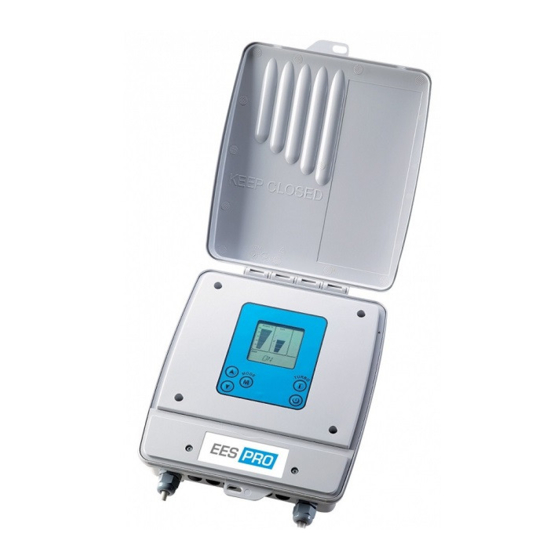
III. CONTENU DU PRODUIT : Désignation pièce qté Commentaires Ce coffret est d’aspect et de dimensions identiques pour tous les modèles. Néanmoins, ses caractéristiques électriques, ses Coffret fonctionnalités et sa constitution interne diffèrent. d’alimentation et de contrôle N.B. : le câble d’alimentation du coffret n’est pas fourni. - Page 6 le détecteur de débit est pré-monté sur Détecteur de un té en 63. La sonde de température est débit et sonde de positionnée sur le T au pied du détecteur de débit. Tous deux se raccordent au bornier du température coffret.
-
Page 7: Installation Du Produit
INSTALLATION DU PRODUIT : • MONTAGE HYDRAULIQUE : IMPORTANT : lors du choix de l’emplacement La cellule ne doit pas être installée en un point haut du circuit pour éviter que de l’air ne s’accumule des différents organes, et avant de réaliser le(s) circuit(s) by-pass d’installation, bien à... -
Page 8: Précautions Vis-À-Vis Des Sondes
Respecter le sens de circulation de l’eau (lèche rouge) au travers du détecteur de débit. Si le détecteur de débit est monté en position horizontale, il faut impérativement que sa tête bleue soit vers le haut, et non vers le bas (des impuretés pourraient s’accumuler dans le mécanisme et entraver son bon fonctionnement) ff... -
Page 9: Montage De La Pompe Ph-Clear
• MONTAGE DE LA POMPE PH-CLEAR : La pompe pH-Clear doit être installée juste après la cellule, idéalement sur une partie verticale de tuyauterie. Lors des détartrages de la cellule (iltration à l’arrêt), l’acide concentré pourra ainsi descendre par gravité vers la cellule, étant plus lourd que l’eau. Le tube de refoulement d’acide est déjà... -
Page 10: Important
• SONDE PH : Introduire l’extrémité de la sonde dans le raccord, et Dévisser le capuchon blanc et retirer la sonde de son lacon de liquide. Oter de la sonde le joint l’enfoncer jusqu’à ce que l’extrémité se positionne torique noir et le capuchon blanc, et les remettre au milieu de la section de passage de l’eau. -
Page 11: Raccordement Des Différents Organes Au Coffret De Contrôle
Epaisseur: 95 mm Longueur du câble vers la cellule: 3,60 mètres • RACCORDEMENT DES DIFFÉRENTS ORGANES AU COFFRET DE CONTRÔLE : Déposer le couvercle du compartiment contenant le bornier. Introduire tous les câbles de raccordement dans le compartiment par les presses-étoupes situés sous les points de raccordement. -
Page 12: Raccordement Du Coffret De Contrôle Au Réseau Électrique
La cellule se raccorde au coffret par les câbles à connecteurs rapides (longueur du câble de environ 3,60 m). Les deux ergots permettent de maintenir chaque paire de connecteurs bien assemblés entre eux. Tester leur bonne connexion en tirant modérément sur chaque connecteur. NE JAMAIS MODIFIER, RACCOURCIR OU RALLONGER CES CÂBLES. -
Page 13: Incorporation Du Sel Dans Le Bassin
INCORPORATION DU SEL DANS LE BASSIN : Avant l'incorporation du sel dans le bassin, dissous) compris entre 100 et 250 ppm T.A.C. (taux d’alcalinité complet de l’eau) compris s’assurer que les paramètres d’équilibre de l’eau • ont individuellement des valeurs correctes : entre 100 et 250 ppm •... -
Page 14: Stabilisation Du Chlore
STABILISATION DU CHLORE : Le chlore généré dans le bassin par la cellule de stabilisant pour la détermination de la masse à d’électrolyse est du chlore actif non stabilisé, qui incorporer. est facilement détruit par les U.V. et la chaleur. Le stabilisant chlore ne se dégrade pas dans le Ain de limiter ce phénomène de destruction lorsque temps. -
Page 15: Réglages Et Fonctions Disponibles
VIII. RÉGLAGES ET FONCTIONS DISPONIBLES : • NIVEAU DE PRODUCTION DE CHLORE (« OUTPUT ») : Sur l’EES seulement, le réglage du niveau de Sur l’EES Pro, l’appareil règle automatiquement production de chlore peut être ajusté manuellement le niveau de production de chlore en fonction du par l’utilisateur, à... -
Page 16: Mode Turbo
à l’intérieur de la plage 550 – 900 mV. • dès qu’un renouvellement d’une partie signiicative (au moins le 1/3) du volume d’eau de Pour cela : la piscine a lieu. • Appuyer une fois sur le bouton : la valeur de si l’on décide de modiier signiicativement le •... -
Page 17: Détartrage De La Cellule Par Injection D'acide Par La Pompe Ph-Clear
sec. paragraphe IV) , et le contact doit se fermer lorsque la couverture est étalée sur le bassin. Il est à utiliser avec l’EES uniquement car celui- ci ne régule pas le taux de chlore présent dans Lorsque la couverture est étalée, l’indication « l’eau de la piscine, mais produit dès lors que la MODE AUX »... -
Page 18: Message D'avertissement Et D'erreur
• INJECTIONS PÉRIODIQUES : S’assurer que la iltration fonctionne • • appuyer sur le bouton pour entrer dans le mode « pH REDUCING – AUTO ». • INJECTION PONCTUELLE : S’assurer que la iltration fonctionne LVL = 2 -> volume = 2 x 70 = 140 cm3… •... -
Page 19: Débit Trop Faible
visible. • Défaire les connecteurs rapides au niveau de la cellule, et vériier qu’il n’y a pas d’encrasssement Nota bene : ce message apparaît aussi, en parallèle (corrosion, …) au niveau des contacts à l’intérieur avec d’autres indicateurs, lorsque la salinité est des connecteurs très excessive, comme signalé... -
Page 20: Remplacement Du Tube De Compression De La Pompe Ph-Clear (Ees Pro Uniquement)
• REMPLACEMENT DU TUBE DE COMPRESSION DE LA POMPE PH-CLEAR (EES PRO UNIQUEMENT) Après son installation, tous les 180 jours, l’appareil • Appuyer quatre fois sur le bouton M. va aficher au bas de l’écran le message « ACID Appuyer sur la lèche : les messages «... -
Page 21: Défaut De Sonde Ph Ou Rédox (Ees Pro Uniquement)
► de la conformité d’une étape, passer à l’étape S’assurer que la valeur de la consigne rédox est correcte. suivante) : ► ► S’assurer de la propreté et de l’intégrité de S’assurer que la valeur de la consigne rédox est correcte. la sonde. -
Page 22: Ne Jamais Frotter Ou Essuyer L'extremite Des Sondes Pour Les Nettoyer
JAMAIS FROTTER ESSUYER Le dégraissage s’effectue en trempant et agitant l’extrémité des sondes dans de l’eau dans laquelle L’EXTREMITE SONDES POUR NETTOYER du savon ou un détergent aura été dissous. Bien rincer les sondes après dégraissage. Si nécessaire, un détartrage s’effectue en trempant quelques minutes l’extrémité... -
Page 23: Changement Du Tube De Compression De La Sonde Péristaltique
Attendre la stabilisation de la valeur afichée, Attendre environ 1 minute puis ajuster cette valeur, à l’aide des lèches, à Eteindre l’appareil (bouton ), puis appuyer celle indiquée sur le lacon de la solution tampon sur le bouton M pour entrer en mode étalonnage rédox Appuyer sur le bouton une fois, le sigle... -
Page 24: Hivernage Passif
CELLULE : Si la iltration est à l’arrêt, la mettre en marche et renouveler l’apport de vinaigre ou d’acide. forcée une minute environ pour faire circuler Rincer cellule à l’eau après l’eau dans la cellule au cas où une injection l’opération) d’acide venait d’avoir lieu. -
Page 25: Concernant Les Sondes
• CONCERNANT LES SONDES : • Disjoncter l’alimentation électrique du coffret de contrôle . • Débrancher les sondes du coffret de contrôle . • Fermer les vannes de sectionnement du by-pass sur lequel elles sont montées . • Déposer les sondes et les mettre dans leur godet de solution tampon comme à la livraison, puis les remiser à... -
Page 26: Xi : Annexe 1 - Aide Au Diagnostic
XI : ANNEXE 1 - AIDE AU DIAGNOSTIC Problème Causes possibles Actions correctives Vériier si un message d’erreur est afiché sur l’écran du coffret, et se L’appareil est en erreur référer à la liste correspondante. L’appareil reste éteint alors qu’il Voir point ultérieur devrait être en route La sonde rédox est mal étalonnée... - Page 27 Problème Causes possibles Actions correctives Procéder à un contrôle et se référer La teneur en chlore libre est au cas précédent en cas de teneur insufisante insufisante Mesurer la concentration en acide isocyanurique. Procéder à L’eau verdit, ou des tâches brunes un renouvellement d’une partie L’eau contient trop de stabilisant apparaissent sur les murs et le fond...
- Page 28 28/84 2015/02 - Indice de révision : B - Code : 29650...
- Page 29 ESS and ESS PRO ELECTROLYSER CHLORINATOR INSTALLATION AND OPERATING INSTRUCTIONS (to be read carefully and kept for future reference) 29/84 2015/02 - Indice de révision : B - Code : 29650...
- Page 30 TABLE OF CONTENTS PRODUCT DESCRIPTION AND OPERATING INSTRUCTIONS: ..........31 SAFETY RECOMMENDATIONS: ....................32 • USER SAFETY: ..........................32 • SAFETY OF MATERIAL AND PREMISES: ..................32 • LOCKING/ UNLOCKING THE KEY PAD: ..................32 III. CONTENTS: ........................... 33 IV. PRODUCT INSTALLATION:......................35 •...
-
Page 31: Product Description And Operating Instructions
PRODUCT DESCRIPTION AND OPERATING INSTRUCTIONS: EES and EES Pro are pool water treatment devices children; that electrolyse salt (Sodium Chloride) dissolved in • An electrolysis cell that is mounted on a by- the pool water. pass loop on the hydraulic circuit after any other devices (pump, ilter, heating, etc.) The process therefore requires that solid salt is irst The salt water electrolysis process offers many... -
Page 32: Safety Recommendations
SAFETY RECOMMENDATIONS: • USER SAFETY The EES and EES Pro electrical/ control panel should be wired in by a qualiied professional, according to the standards in effect in the country of installation. It should be located at least 3.5 m from the pool. -
Page 33: Product Components
III. PRODUCT COMPONENTS: Part Comments The panels of all models have the same appearance and the same dimensions. Nevertheless , its electrical spciications, functional speciications and te Electrical/ control internal components are different. N.B.: the power cable panel is not inlcuded. Set of 2 screws and to mount the panel on the wall 2 bushings... - Page 34 The l ow detector is premounted on a Tee, diameter 63 mm. The temperature probe is Flow detector and positionned on the Tee at the base of the l ow temperature sensor detector. Both are connected to a terminal in the control panel.
-
Page 35: Hydraulic Connections
INSTALLATION: • HYDRAULIC CONNECTIONS IMPORTANT: when selecting the installation the diagram is respected. sites of the various components, and before To avoid the accumulation of air in the cell in the creating the by-pass loops on the installation, event that air enters the hydraulic circuit, the cell make sure that the power cables of each of should not be installed at a high point on the the components are long enough to reach the... - Page 36 Respect the direction of low of water (red arrow) through the low detector. If the low detector is mounted horizontally, the blue head must be oriented upwards (otherwise impurities can gather in the mechanism and prevent ff fi fi correct operation) ff...
-
Page 37: Installation Of The Ph-Clear Pump
• INSTALLATION OF THE PH-CLEAR PUMP: The pH-Clear pump should be installed downstream, just after the cell and ideally on a vertical section of pipe. During the cell descaling process (iltration stopped), the concentrated acid, being heavier than water, will descend into the cell. The acid injec37ion tubing is already in place, the end piece inserted into the pipe on which the pump is mounted. -
Page 38: Installing The Electrical/ Control Panel
• PH PROBE: Unscrew the white cap and withdraw the probe Push the end of the probe into the union until the from its vial of liquid. Remove the black o-ring and end of the probe is located in the centre of the pipe through which the water is lowing. -
Page 39: Connection Of The Various Components To The Electrical Panel
Thickness: 95 mm Cell cable length: 3.60 m • CONNECTION OF THE VARIOUS COMPONENTS TO THE ELECTRICAL PANEL : Remove the cover from the compartment containing into the panel as shown. the terminal connectionsas per the diagram below. Pass the connection cables through the cable gland The cell is connected to the panel with cables itted Temperature probe (White) Flow switch (Blue) - Page 40 with quick it connectors (cable length approx. 3.60 m). The two tabs keep each pair of connectors correctly assembled with respect to each other. Check that they are irmly connected by pulling lightly on each connector. NEVER MODIFY, SHORTEN OR LENGTHEN THE CABLES.
-
Page 41: Adding Salt To The Pool
ADDING SALT TO THE POOL: Before adding salt to the pool, check that the each and 250 ppm of the water equilibrium parameters are within • T.A. (total alkalinity), between 100 and 250 ppm range: Use these parameters to ensure that the water is •... -
Page 42: Chlorine Stabilisation
CHLORINE STABILISATION: The Chlorine introduced into the pool by the The Chlorine stabiliser does not break down over electrolysis cell is unstabilised active Chlorine that time; if the pool was disinfected with Chlorine is easily destroyed by UV light and heat. before the electrolyser was installed, measure the initial stabiliser concentration before adding any To limit this phenomenon while the pool is... -
Page 43: Parameter Settings And Functions
VIII. PARAMETER SETTINGS AND FUNCTIONS: • CHLORINE OUTPUT: On the EES models only, the chlorine output can be EES Pro models automatically adjust the Chlorine adjusted manually by the user by pressing the two output depending on the Chlorine demand arrow keys ▲... -
Page 44: Turbo Mode
The Redox set point may be modiied within the was winterized if a signiicant volume of the pool water (more range 550 – 900 mV. • than 1/3) is renewed To do this: • if a decision to alter the stabiliser concentration Press the button once: the current Redox set •... -
Page 45: Punctual Or Periodic Reduction Of The Ph By The Ph-Clear Pump
by UV radiation and is not being consumed by the production of Chlorine is decreased to 20% by pollution introduced by bathers, therefore there default. is a risk that it will accumulate in the water while The value by which Chlorine production is decreased iltration is running. -
Page 46: Warning And Error Messages
• PERIODIC INJECTION: Make sure that iltration is running • • press the button to enter pH REDUCING – AUTO mode. • PUNCTUAL INJECTION: Make sure that iltration is running LVL = 2 -> volume = 2 x 70 = 140 cm3… •... - Page 47 compartment of the panel. Contact your agent if cell power cable are correctly tightened. any damage is visible. ► Undo the quick connectors at the cell, check that the contacts inside the connectors are not Nota bene: This message is also displayed, in dirty (corrosion, etc.) parallel with other indicators if the salt concentration is too high as described previously.
-
Page 48: Replacing The Ph-Clear Pump Compression Tube (Ees Pro Only)
• REPLACING THE PH-CLEAR PUMP COMPRESSION TUBE (EES PRO ONLY) After installation, every 180 days the device will • Press the button M four times : the messages NEW PIPE display the message ACID PIPE, recommending • Press the arrow replacement of the pH-Clear peristaltic pump and 180 DAYS are displayed at the bottom of the compression tube. -
Page 49: Ph Or Redox Probe Faults (Ees Pro Only)
► Calibrate the Redox probe with the (abnormally low) Redox potential ► Wait for the Chlorine concentration to fall displayed. ► Calibrate the Redox probe and to see if the phenomenon reoccurs. ► Check that iltration is running for long ORP LOW: this message is displayed when the value measured by the Redox probe is less than enough each day (at least 10 hours a day... -
Page 50: Calibrating The Ph Probe (Ees Pro Only)
NEVER CLEAN THE TIPS OF THE PROBES BY after degreasing. RUBBING OR WIPING THEM After being descaled and degreased, the probes should be recalibrated (see the next paragraph), If necessary, descale the electrodes by soaking and the correspondence between the Redox the tips of the electrodes in a 10% solution of potential measured by the Redox probe and the Hydrochloric acid for a few minutes. - Page 51 Wait approximately 1 minute Wait for the read out to stabilise, then, using the arrow keys, adjust this value to that indicated on Switch the device off ( button), then press M the redox buffer solution bottle. to enter calibration mode. Press the button M again to conirm this setting.
-
Page 52: Manual Dismantling And Descaling Of The Cell
• MANUAL DISMANTLING AND DESCALING OF THE CELL: If iltration is topped, force it on for approximately frothing), one minute so that water lows through the cell in If scale is still present, empty the cell and repeat case acid was just injected. the procedure with vinegar or acid. -
Page 53: Active Winterizing
• B) ACTIVE WINTERIZING: Cut the power supply to the electrical/ control panel. The various components may be left in place if suitable winterizing chemicals are added to the water to prevent the growth of algae andiltration is run every day. Filtration must notably be run while the ambient temperature in the plant room where the material is installed is +2°C or less. -
Page 54: Xi. Appendix 1 - Troubleshooting
XI. APPENDIX 1 - TROUBLESHOOTING Problem Possible cause Solution Check to see if an error message is displayed on the control The device is not working correctly panel screen, and refer to the corresponding list. The device remains off even though See above it should be running The Redox probe is badly... - Page 55 Problem Possible cause Solution The concentration of free Chlorine Check the concentration of free is too low Chlorine, correct if necessary. Measure the concentration of Isocyanuric acid. Renew a fraction Water is turning green, or brown The water contains too much of the pool water volume to bring stabiliser stains are appearing on the pool...
- Page 56 56/84 2015/02 - Indice de révision : B - Code : 29650...
- Page 57 EES und EES Pro Salzelektrolysegerät MONTAGE- UND BEDIENUNGSANLEITUNG (Bitte lesen Sie sich diese Anleitung sorgfältig durch und bewahren Sie sie auf) 57/84 2015/02 - Indice de révision : B - Code : 29650...
- Page 58 INHALTSVERZEICHNIS PRODUKTBESCHREIBUNG UND HINWEISE ZUM BETRIEB: ........... 59 SICHERHEITSHINWEISE: ......................60 • SICHERHEIT DES NUTZERS: ......................60 • SICHERHEIT DER KOMPONENTEN UND DES ORTES: ..............60 • VERRIEGELN/ ENTRIEGELN DER TASTATUR: ................60 III. BESTANDTEILE: ..........................61 IV. MONTAGE: ............................. 63 • HYDRAULISCHE ANSCHLÜSSE ......................63 •...
-
Page 59: Produktbeschreibung Und Hinweise Zum Betrieb
PRODUKTBESCHREIBUNG UND HINWEISE ZUM BETRIEB: EES und EES Pro sind Geräte zur Plege des jedoch nicht. Die pH-Clear Pumpe führt außerdem Schwimmbadwassers, die im Wasser aufgelöstes eine automatische Entkalkung der Zelle durch, Salz (Natriumchlorid) durch Elektrolyse zersetzen. während die Filtration ausgeschaltet ist. Für diesen Prozess muss festes Salz zunächst Das Gerät wird im Technikraum des Pools installiert;... -
Page 60: Sicherheitshinweise
SICHERHEITSHINWEISE: • SICHERHEIT DES NUTZERS Das EES und EES Pro Steuergerät ist von einem qualiizierten Fachmann gemäß den im Installationsland geltenden Bestimmungen zu verkabeln. Es sollte eine Entfernung zum Pool von mindestens 3,50 m einhalten. Sollte dies nicht möglich sein, so kann die Entfernung zum Pool auch weniger als 3,50 m, Anmerkung: Die Elektrolyse-Zelle wird von einer 12V... -
Page 61: Bestandteile
III. BESTANDTEILE: Teil Anzahl Anmerkungen Die Steuergeräte aller Modelle sind von außen identisch und haben dieselben Abmessungen. Dennoch unterscheiden sie sich in Steuergerät Leistungsmerkmalen, Funktionen und innerem Aufbau. Achtung: Das Stromkabel ist nicht enthalten. Set mit zur Wandmontage des Steuergeräts 2 Schrauben und 2 Gewindebuchsen An einem Ende hat das Kabel... - Page 62 Der Strömungswächter ist auf einem T-Stück, Durchmesser 63 mm, vormontiert. Der Strömungswächter Temperatur-Sensor ist auf dem T-Stück unten am Stömungswächter angebracht. und Temperatur- Sensor Beide sind an eine Klemme im Steuergerät angeschlossen. Die pH-Clear Pumpe dient dazu, Säure in den hydraulischen Kreislauf einzuspritzen.
-
Page 63: Montage
MONTAGE • HYDRAULISCHE ANSCHLÜSSE Wichtig: Wenn Sie den Standort für die Die Zelle sollte an einem hohen Punkt am Hydraulik- Kreislauf installiert werden, um Luftansammlungen verschiedenen Bestandteile festlegen und noch bevor Sie die Bypass-Verbindungen herstellen, - sollte denn Luft in den Hydraulik-Kreislauf sollten Sie sich unbedingt vergewissern, dass gelangen - in der Zelle zu vermeiden. - Page 64 Halten Sie die Strömungsrichtung des Wassers (roter Pfeil) durch den Strömungswächter ein. Wurde der Strömungswächter horizontal montiert, so muss die blaue Kappe nach oben zeigen (ansonsten sammeln sich Verschmutzungen an, ff fi fi die den korrekten Betrieb behindern könnten). ff fi...
-
Page 65: Installation Der Ph-Clear Pumpe
• INSTALLATION DER PH-CLEAR PUMPE: Die pH-Clear Pumpe sollte stromabwärts installiert werden, und zwar unmittelbar nach der Zelle und idealerweise an einem senkrechten Abschnitt der Rohrleitung. Beim Entkalkungs-Prozess der Zelle (die Filtration ist ausgeschaltet) strömt die konzentrierte Säure, da sie schwerer ist als Wasser, in die Zelle. Die Säure-Einspritz-Leitung ist bereits montiert, das Endstück ist in die Leitung eingeführt, an der die Pumpe montiert ist. -
Page 66: Installation Des Steuergeräts
• PH-SONDE: Schrauben Sie die weiße Kappe ab und ziehen Sie dabei keines der abnehmbaren Teile verlieren. Sie die Sonde aus ihrem Flüssigkeitsbehälter. Entfernen Sie den schwarzen O-Ring und die weiße Ziehen Sie den Kappe von der schwarzen Ring, Sonde metallene legen sie beides Unterlegscheibe... -
Page 67: Anschluss Der Komponenten An Das Steuergerät
Stärke: 95 mm Kabellänge: 3,60 m • ANSCHLUSS DER VERSCHIEDENEN KOMPONENTEN AN DAS STEUERGERÄT: Entfernen Sie die Blende über den Klemmen wie in Führen Anschlusskabel durch der Abbildung gezeigt. Kabeldurchführungen in das Steuergerät wie unten dargestellt. Temperatur-Sensor (Weiß) Strömungswächter (Blau) pH-Clear (Rot) pH-Sonde Redox-Sonde... -
Page 68: Verkabelung Des Steuergeräts
Die Zelle ist an das Steuergerät mit Kabeln angeschlossen, die über Schnellsteckanschlüsse verfügen (Kabellänge 3,60 beiden Schildchen sorgen dafür, dass jedes Steckanschluss-Paar richtig montiert wird. Vergewissern sich, dass diese sicher anschlossen sind, indem sie leicht an jedem Steckanschluss ziehen. KABEL DÜRFEN UNTER KEINEN... - Page 69 ZUGABE VON SALZ ZUM SCHWIMMBADWASSER: gelöstem Kalzium) zwischen 100 und 250 ppm Überprüfen Sie vor der Zugabe von Salz zum Schwimmbadwasser, sich Wasser- • Gesamtalkalität zwischen 100 und 250 ppm Parameter innerhalb folgender Bereiche beinden: Anhand dieser Vorgaben können Sie sicherstellen, pH-Wert, idealerweise zwischen 7,2 und 7,4 mit dass sich das Wasser im richtigen Gleichgewicht •...
-
Page 70: Stabilisierung Des Chlors
STABILISIERUNG DES CHLORS: Der Chlor-Stabilisator löst sich auch im Laufe Bei dem durch die Elektrolyse-Zelle ins Poolwasser eingeführten Chlor handelt es sich um instabiles, der Zeit nicht auf; wurde der Pool vor Installation aktives Chlor, das durch UV-Strahlen und Wärme des Elektrolysegeräts mit Chlor desiniziert, so leicht wieder zerstört werden kann. -
Page 71: Parameter: Einstellungen Und Funktionen
VIII. PARAMETER: EINSTELLUNGEN UND FUNKTIONEN: • CHLORPRODUKTION: Nur bei den EES-Modellen lässt sich die Chlor- Bei den EES-Pro Modellen ist die Chlorproduktion Produktion manuell vom Nutzer regulieren und zwar automatisch geregelt und abhängig von der durch Betätigen der beiden Pfeiltasten ▲ und ▼. tatsächlich notwendigen Menge an Chlor. -
Page 72: Turbo-Modus
Der Redox-Sollwert kann innerhalb des Bereichs Pool über Winter außer Betrieb war 550 - 900 mV modiiziert werden. Wenn ein beträchtliches Wasservolumen (mehr • als 1/3) ausgetauscht wurde Dazu ist Folgendes erforderlich: Wenn Konzentration Stabilisators • • Drücken Sie die Taste 1-mal: der derzeitige absichtlich geändert wurde Redox-Sollwert wird angezeigt... -
Page 73: Entkalken Der Zelle Durch Einspritzen Von Säure Mit Hilfe Der Ph-Clear Pumpe
• ABDECKUNGS-MODUS Dieser Modus betrifft Pools, die mit einer Rollladen- Die beiden Drähte des potentialfreien Kontakts sollten Abdeckung versehen sind und über eine Vorrichtung mit der COVER-Klemme im Steuergerät verbunden verfügen, die das Schließen der Abdeckung registriert werden (siehe Abschnitt IV) und der Kontakt sollte und einen potentialfreien Kontakt auslöst. -
Page 74: Einmalige Oder Regelmässige Senkung Des Ph-Werts Anhand Der Ph-Clear Pumpe
• EINMALIGE ODER REGELMÄSSIGE SENKUNG DES PH-WERTS ANHAND DER PH-CLEAR PUMPE Diese Funktion betrifft EES Pro; für EES gilt sie nur, dass sie während der Filtrationszyklen Säure falls pH-Clear installiert wurde. einspritzt und zwar entweder in regelmäßigen Abständen oder einmalig: Die pH-Clear Pumpe kann so eingestellt werden, •... -
Page 75: Elektrische Probleme Mit Der Zelle
• ELEKTRISCHE PROBLEME MIT DER ZELLE 2 Arten von elektrischen Problemen werden angezeigt: Zelle ► • Kurzschluss im Stromversorgungskreis der Zelle: die Entfernen Sie die Blende über den Klemmen Nachricht SHRT CELL erscheint unten im Anzeigefeld des Steuergeräts und vergewissern Sie sich, ►... -
Page 76: Austauschen Des Schlauchs Der Ph-Clear Pumpe (Nur Bei Ees Pro)
• TEMPERATUR IM STEUERGERÄT ZU HOCH Liegt die Temperatur innerhalb des Steuergeräts einer Temperatur von 70°C ist die Chlorproduktion auf 50% beschränkt. über 65°C, so erscheint das Bildzeichen . Über • AUSTAUSCHEN DES SCHLAUCHS DER PH-CLEAR PUMPE (NUR BEI EES PRO) Nach der Installation und in Abständen von 180 •... - Page 77 Wenn Sie sich diesen niedrigen Wert nicht Sonde und messen Sie erneut. anderweitig erklären können, so versuchen Sie das ► Wenn die von EES und dem Photometer Problem anhand folgender Schritte zu lösen (führt gemessenen Werte übereinstimmen und der ein Schritt zu keiner Lösung, so fahren Sie mit dem pH-Wert unter 6,7 liegt, so fügen Sie Basen hinzu, um den pH-Wert zu seinem Sollwert nächsten fort):...
-
Page 78: Instandhaltung
INSTANDHALTUNG • INSTANDHALTUNG DER PH- UND REDOX-SONDEN (NUR BEI EES PRO) An den pH- und Redox-Sonden kann sich bei deren Falls nötig, entkalken Sie die Elektroden, indem Gebrauch Kalk ablagern; auf ihren Spitzen können Sie deren Spitzen für einige Minuten in einer 10%-Lösung an Salzsäure eintauchen. -
Page 79: Austauschen Des Schlauchs Der Sonde
während der Badesaison etwa alle 6 Wochen • Vor der ersten Inbetriebnahme des Geräts • • zu Beginn der Badesaison Zum Kalibrieren benötigen Sie Folgendes: • ein Glas Leitungswasser oder Wasserhahn in der Nähe • Redox-Pufferlösung • • VORGEHENSWEISE: Schalten Sie das Gerät ein, aber lassen Sie Sie sodann M um mit der Kalibrierung zu die Filterpumpe ausgeschaltet (ST-BY Modus);... -
Page 80: Manuelles Abmontieren Und Entkalken Der Zelle
• MANUELLES ABMONTIEREN UND ENTKALKEN DER ZELLE hat (das Schäumen hört auf) Ist die Filtration ausgeschaltet, so schalten Sie sie für etwa eine Minute wieder ein, damit Wasser Ist der Kalk immer noch vorhanden, so entleeren durch die Zelle ließen kann (für den Fall, dass Sie die Zelle und wiederholen Sie den Vorgang Säure eingespritzt worden war). - Page 81 • SONDEN: • Unterbrechen Sie die Stromverbindung zum Steuergerät • Unterbrechen Sie die Verbindung zwischen Sonden und Steuergerät • Schließen Sie das Absperr-Ventil der Bypass-Verbindung, auf der die Sonden montiert sind Entfernen Sie die Sonden und legen Sie sie in ihre Behälter mit Pufferlösung; verwahren Sie sie an •...
-
Page 82: Xi. Anhang 1: Fehlerbehebung
XI. ANHANG 1: FEHLERBEHEBUNG Mögliche Ursache Lösung Problem Überprüfen Sie, ob auf der Anzeige des Steuergeräts eine Das Gerät läuft nicht einwandfrei Fehlermeldung angezeigt wird und vergleichen Sie die dazugehörige Aufstellung Das Gerät bleibt ausgeschaltet, obwohl es seinen Betrieb Siehe oben aufgenommen haben sollte Die Redox-Sonde ist unzureichend Kalibrieren Sie die Redox-Sonde... - Page 83 Mögliche Ursache Lösung Problem Überprüfen Sie die Konzentration Die Konzentration an freiem Chlor von freiem Chlor und korrigieren ist zu niedrig Sie sie, falls nötig Messen Sie die Konzentration der Isocyansäure. Erneuern Das Wasser wird grün oder Das Wasser enthält zu viele Sie einen kleinen Teil des es werden braune Flecken an Stabilisatoren...
- Page 84 84/84 2015/02 - Indice de révision : B - Code : 29650...