Gtec SATURN Série Manuel D'installation
Masquer les pouces
Voir aussi pour SATURN Série:
- Manuel d'installation (279 pages) ,
- Manuel d'installation et d'utilisation (274 pages)
Table des Matières
Publicité
Les langues disponibles
Les langues disponibles
Liens rapides
Publicité
Chapitres
Table des Matières
Dépannage

Manuels Connexes pour Gtec SATURN Série


Sommaire des Matières pour Gtec SATURN Série
- Page 1 UPS (Uninterruptible Power Supply) SATURN 30-40 kVA Manuale d’installazione ed uso Installation and use manual Installations und Bedienungsanleitung Manuel d’installation et d’utilisation Manual de instalacìon y uso...
- Page 3 - SATURN 30-40- NTRODUZIONE Vi ringraziamo per la scelta del nostro prodotto. La nostra azienda è specializzata nella progettazione, nello sviluppo e nella produzione di gruppi statici di continuità (UPS). L’UPS descritto in questo manuale è un prodotto di alta qualità, attentamente progettato e costruito allo scopo di garantire le migliori prestazioni.
-
Page 4: Table Des Matières
NDICE PRESENTAZIONE ISTE ANTERIORI ISTA CONNESSIONI ISTA POSTERIORE ISTA PANNELLO DI CONTROLLO NGRESSO YPASS EPARATO OPZIONALE RASFORMATORE INTERNO OPZIONALE 208V ( ERSIONE OPZIONALE ISPOSITIVI DI PROTEZIONE ESTERNI EZIONE DEI CAVI ONNESSIONI ISTA TRASFORMATORI INTERNI ATI TECNICI 115V 110V) ECLASSAMENTO DEL CARICO ONNESSIONI INSTALLAZIONE ’UPS... - Page 5 OLLEGAMENTO DEL BYPASS DI MANUTENZIONE REMOTO ONNESSIONE ATTERY OPZIONALE MPOSTAZIONE DELLA CAPACITÀ NOMINALE DI BATTERIA CONFIGURAZIONE SOFTWARE ENSORE DI TEMPERATURA ESTERNO INOTTICO REMOTO OPZIONALE UTILIZZO ESCRIZIONE PERAZIONI PRELIMINARI E PRIMA ACCENSIONE CCENSIONE DA RETE CCENSIONE DA BATTERIA ’UPS PEGNIMENTO DELL ISPLAY GRAFICO ENU DISPLAY ODALITÀ...
-
Page 6: Presentazione
PRESENTAZIONE Gli UPS della serie SATURN sono stati progettati utilizzando lo stato dell’arte della tecnologia oggi disponibile, in modo da garantire all’utilizzatore le massime prestazioni. L’impiego delle nuove schede di controllo basate su architettura multiprocessore (DSP + P inside) e l’adozione di particolari soluzioni circuitali, che utilizzano componenti di ultimissima generazione, hanno permesso di raggiungere elevate prestazioni quali: ... -
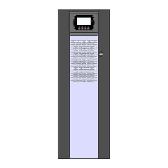
Page 7: Viste Anteriori Ups
ISTE ANTERIORI Pannello di controllo con display grafico Ruote per la movimentazione dell’UPS Porta frontale con serratura Piedino Griglia di aerazione... - Page 8 Da sinistra: Sezionatore di ingresso / Sezionatore di bypass Slot per schede accessorie di comunicazione separato (opzionale) / Sezionatore di bypass manuale / Sezionatore di uscita Da sinistra: Pulsante per partenza da batteria COLD START (sopra) / Connettore R.E.P.O. (Remote Emergency Pannello copri-morsetti Power Off) / Porta contatti per AS400 / Porta comunicazione USB / Porta comunicazione RS232...
-
Page 9: Vista Connessioni Ups
ISTA CONNESSIONI Connessioni di potenza: BATTERIA ESTERNA, INGRESSO, BYPASS SEPARATO (opzionale), USCITA Connessione per segnale di sincronismo esterno Connessione per comando bypass di manutenzione remoto Connessione per sonda di temperatura esterna Battery Box... -
Page 10: Vista Posteriore Ups
ISTA POSTERIORE Alloggiamento scheda relè potenza Ventole schede di potenza (opzionale) Prese EnergyShare / Aux Output (10A max.) e Ventola carica batterie relativa protezione (opzionale) -
Page 11: Vista Pannello Di Controllo
ISTA PANNELLO DI CONTROLLO LED funzionamento da rete Acceso fisso: funzionamento da rete con linea bypass buona e inverter sincronizzato Lampeggiante: funzionamento da rete con linea bypass non buona o disabilitata e/o inverter non sincronizzato Lampeggiante in Stand-by: funzione di riaccensione programmata attiva e rete presente LED funzionamento da batteria ... -
Page 12: Ngresso Ypass Eparato Opzionale
NGRESSO YPASS EPARATO OPZIONALE LA SERIE DI UPS NELLA VERSIONE (OPZIONALE) PRESENTA LA LINEA DI BYPASS SEPARATA DA QUELLA DI INGRESSO. La serie di UPS con Bypass Separato consente un collegamento distinto tra la linea d’ingresso e la linea di bypass. L’uscita dell’UPS sarà... -
Page 13: Versione 208V ( Opzionale )
208V ( ERSIONE OPZIONALE LA SERIE DI UPS NELLA VERSIONE 208V (OPZIONALE) SI DIFFERENZIA DALLA VERSIONE STANDARD PER LA DIFFERENTE TENSIONE DI INGRESSO E USCITA. QUESTO COMPORTA UNA SERIE DI PARAMETRI DIFFERENTI DALLA VERSIONE STANDARD, ELENCATI DI SEGUITO. ATTENZIONE: I dati contenuti all’interno di questo paragrafo sono da intendersi validi solo ed esclusivamente per la Versione 208V ISPOSITIVI DI PROTEZIONE ESTERNI MAGNETOTERMICO... -
Page 14: Sezione Dei Cavi
EZIONE DEI CAVI Si consiglia di far passare i cavi di INGRESSO/USCITA e di BATTERIA sotto l’UPS. Per il dimensionamento della sezione dei cavi d’ingresso e uscita fare riferimento alla seguente tabella: Sezione cavi (mmq) INGRESSO rete / USCITA BATTERIA ESTERNA ** (opzionale) bypass separato (opzionale) L1/L2/L3 L1/L2/L3... -
Page 15: Dati Tecnici
ATI TECNICI Modelli UPS 30kVA 40 kVA STADIO DI INGRESSO Tensione Nominale 208-220-228 Vac Trifase con neutro (4 wire) Frequenza Nominale 50-60Hz 20% @ 100% load Tolleranza accettata tensione ingresso per non intervento da batteria (riferita a 220Vac) -40% +20% @50% load ... -
Page 16: Declassamento Del Carico ( A 115V E 110V)
Modelli UPS 30kVA 40 kVA STADIO CARICA BATTERIE 240Vdc Tensione nominale Corrente massima di ricarica Algoritmo caricabatteria Due livelli con compensazione della temperatura Switching current mode analogico sotto il controllo del P (regolazione PWM di tensione Tecnologia e corrente di carica) Tolleranza tensione di ingresso per ricarica 190-264Vac alla massima corrente... -
Page 17: Connessioni
ONNESSIONI La prima connessione da effettuare e' quella del conduttore di protezione (cavo di terra). L'UPS deve funzionare con il collegamento all'impianto di terra IL NEUTRO DI INGRESSO DEVE SEMPRE ESSERE COLLEGATO Collegare i cavi d'ingresso e d'uscita alla morsettiera come indicato nella figura sottostante: Nota: le connessioni al modulo BATTERIA devono essere effettuate solo se presente il Battery Box (vedi paragrafo "Connessioni UPS al Battery Box (opzionale)") -
Page 18: Installazione
INSTALLAZIONE TUTTE OPERAZIONI DESCRITTE QUESTA SEZIONE DEVONO ESSERE ESEGUITE ESCLUSIVAMENTE DA PERSONALE QUALIFICATO. L’Azienda non si assume nessuna responsabilità per danneggiamenti causati da collegamenti errati o da operazioni non descritte in questo manuale. ’UPS MMAGAZZINAMENTO DELL Il locale d'immagazzinamento dovrà rispettare le seguenti caratteristiche: Temperatura: 0°÷40°C (32°÷104°F) Grado di umidità... -
Page 19: Compatibilità Elettromagnetica
OMPATIBILITÀ ELETTROMAGNETICA Questo Gruppo di Continuità (UPS) è un prodotto che rispetta le normative vigenti di compatibilità elettromagnetica (categoria C2). In ambiente domestico può provocare interferenze radio. L’utilizzatore potrebbe dover adottare provvedimenti supplementari. Questo prodotto è dedicato ad un uso professionale in ambienti industriali e commerciali. Il collegamento ai connettori USB e RS232 deve essere realizzato con i cavi in dotazione o comunque con cavi schermati e di lunghezza inferiore ai 3 metri. -
Page 20: Batterie Interne
ATTERIE NTERNE PRECAUZIONI E NORME ATTENZIONE: Se l’UPS è provvisto DI BATTERIE INTERNE seguire tutte le seguenti PER LA SICUREZZA L'UPS presenta al suo interno delle tensioni elettriche PERICOLOSE anche con interruttori d’ingresso e/o di batteria aperti. L'interno dell'UPS è protetto da pannelli di sicurezza che non devono essere rimossi da personale non qualificato. Tutte le operazioni di installazione e di manutenzione o che implicano l'accesso all'interno dell'UPS richiedono l'utilizzo di attrezzi e devono essere eseguite ESCLUSIVAMENTE da personale qualificato. -
Page 21: Rimozione Dell 'Ups Dal Pallet
’UPS IMOZIONE DELL DAL PALLET ATTENZIONE: PER EVITARE DANNI A PERSONE E/O ALL'APPARECCHIATURA SEGUIRE SCRUPOLOSAMENTE LE SEGUENTI INDICAZIONI. ALCUNE DELLE SEGUENTI OPERAZIONI NECESSITANO IL LAVORO DI DUE PERSONE. Tagliare le regge e sfilare dall'alto la scatola di Rimuovere le 2 staffe che fissano l’UPS al pallet svitando le cartone. -
Page 22: Controllo Preliminare Del Contenuto
ONTROLLO PRELIMINARE DEL CONTENUTO Dopo l’apertura dell’imballo, per prima cosa procedere alla verifica del contenuto: scivoli in lamiera, cartolina di garanzia, manuale d'uso, manuale di sicurezza, certificato di collaudo, cavo di collegamento seriale, nr. 4 fusibili di batteria (da inserire nei portafusibili "SWBATT"), chiave della porta. ’UPS OSIZIONAMENTO DELL Nel posizionamento si dovrà... -
Page 23: Schemi Di Connessione All Impianto Elettrico
OLLEGAMENTI ELETTRICI ATTENZIONE: è richiesto un sistema di distribuzione trifase a 4 fili. L’UPS deve essere collegato ad una linea di alimentazione 3 fasi + neutro + PE (terra di protezione) di tipo TT, TN o IT; è pertanto necessario rispettare la rotazione delle fasi. Sono disponibili TRANSFORMER BOX (opzionali) per convertire gli impianti di distribuzione da 3 fili a 4 fili. - Page 24 UPS senza variazione di regime di neutro e con ingresso bypass separato UPS con isolamento galvanico in ingresso e con ingresso bypass separato UPS con isolamento galvanico in uscita e con ingresso bypass separato...
- Page 25 Bypass separato su linee separate: se è presente l'opzione del bypass separato si dovranno posizionare i dispositivi di protezione sia sulla linea principale di alimentazione che sulla linea dedicata al bypass. Nota: il neutro della linea di ingresso e quello di bypass sono accomunati all’interno dell’apparecchiatura, pertanto dovranno essere riferiti allo stesso potenziale.
-
Page 26: Protezioni Interne All 'Ups
’UPS ROTEZIONI INTERNE ALL Nella tabella sottostante sono riportate le taglie di sezionatori e dei fusibili di batteria (SWBATT) accessibili sul fronte dell'UPS. Sono inoltre indicate le correnti massime d'ingresso e le correnti nominali d'uscita. La sostituzione di un fusibile deve avvenire con un uno della stesso tipo e portata indicati in tabella. Sezionatori e Correnti Mod. -
Page 27: Dispositivi Di Protezione Esterni
ISPOSITIVI DI PROTEZIONE ESTERNI MAGNETOTERMICO Per la predisposizione della linea di alimentazione installare a monte dell'UPS un interruttore magnetotermico con curva di intervento C (o D in funzione del tipo di carico) seguendo quanto indicato nella tabella sottostante: Protezioni esterne automatiche * Mod. -
Page 28: Sezione Dei Cavi
EZIONE DEI CAVI Si consiglia di far passare i cavi di INGRESSO/USCITA e di BATTERIA sotto l’UPS. Per il dimensionamento della sezione dei cavi d’ingresso e uscita fare riferimento alla seguente tabella: Sezione cavi (mmq) INGRESSO rete / USCITA BATTERIA ESTERNA ** (opzionale) bypass separato (opzionale) L1/L2/L3 L1/L2/L3... -
Page 29: Connessioni Del Modello Con Bypass Separato
ONNESSIONI DEL MODELLO CON BYPASS SEPARATO La prima connessione da effettuare e' quella del conduttore di protezione (cavo di terra), da collegare alla vite siglata PE. L'UPS deve funzionare con il collegamento con l'impianto di terra IL NEUTRO DI INGRESSO E DI BYPASS DEVONO ESSERE SEMPRE COLLEGATI. LE LINEE DI INGRESSO E DI BYPASS DEVONO ESSERE RIFERITE ALLO STESSO POTENZIALE DI NEUTRO. -
Page 30: R.e.p.o
NOTE: - Stringere le fascette solo dopo aver serrato i cavi nei relativi morsetti di potenza. Preformare i cablaggi in modo che, allo stringere della fascetta, non sforzino nei morsetti di potenza. R.E.P.O. Questo ingresso isolato è utilizzato per spegnere l’UPS a distanza in caso di emergenza. L’UPS viene fornito dalla fabbrica con i morsetti di “Remote Emergency Power Off”... -
Page 31: Collegamento Del Bypass Di Manutenzione Remoto
OLLEGAMENTO DEL BYPASS DI MANUTENZIONE REMOTO E' possibile installare un bypass di manutenzione aggiuntivo su un quadro elettrico periferico (vedi schema seguente), per consentire, ad esempio, la sostituzione dell'UPS senza interrompere l'alimentazione al carico. Nota: l'azienda mette a disposizione questo accessorio già preassemblato in box plastico IP65. E' assolutamente necessario collegare il morsetto "SERVICE BYPASS"... -
Page 32: Connessione Ups Al Battery Box ( Opzionale )
ONNESSIONE ATTERY OPZIONALE IL COLLEGAMENTO TRA UPS E BATTERY BOX DEVE ESSERE ESEGUITO CON APPARECCHIATURE SPENTE E SCOLLEGATE DALLA RETE ELETTRICA PROCEDURA DI SPEGNIMENTO DELL’UPS: Spegnere tutte le apparecchiature connesse all’UPS o utilizzare (se installata) l'opzione di bypass remoto. ... -
Page 33: Impostazione Della Capacità Nominale Di Batteria - Configurazione Software
MPOSTAZIONE DELLA CAPACITÀ NOMINALE DI BATTERIA CONFIGURAZIONE SOFTWARE Dopo aver installato un BATTERY BOX è necessario configurare l’UPS per aggiornare il valore di capacità nominale (Ah totali batterie interne all’UPS + batterie esterne). Per eseguire tale operazione è necessario utilizzare il software di configurazione dedicato. ENSORE DI TEMPERATURA ESTERNO Questo ingresso NON ISOLATO è... -
Page 34: Utilizzo
UTILIZZO ESCRIZIONE Lo scopo dell'UPS è quello di garantire una perfetta tensione di alimentazione alle apparecchiature ad esso collegate, sia in presenza che in assenza di rete. Una volta collegato e alimentato, l’UPS provvede a generare una tensione alternata sinusoidale di ampiezza e frequenza stabili, indipendentemente dagli sbalzi e/o variazioni presenti nella rete elettrica. -
Page 35: Operazioni Preliminari E Prima Accensione
PERAZIONI PRELIMINARI E PRIMA ACCENSIONE Controllo visivo della connessione Verificare che tutte le connessioni siano state effettuate seguendo scrupolosamente quanto riportato nel paragrafo "Collegamenti elettrici". Verificare che tutti i sezionatori siano aperti. Chiusura portafusibili di batteria Chiudere i 4 portafusibili di batteria (SWBATT) mostrati nella figura sottostante. ATTENZIONE: se è... - Page 36 Dopo alcuni secondi, verificare che si accenda il display e che l'UPS si predisponga in modalità "STAND-BY". Se a display compare un messaggio indicante l’errato senso ciclico delle fasi di ingresso, eseguire le seguenti operazioni: aprire tutti i sezionatori e d’ingresso e uscita ...
-
Page 37: Accensione Da Rete
CCENSIONE DA RETE Chiudere i sezionatori d'ingresso SWIN e SWBYP (se presente) e lasciare aperto il sezionatore di manutenzione SWMB. Dopo qualche istante l'UPS si attiva, viene effettuata la precarica dei condensatori e lampeggia il led "Blocco / stand-by": L'UPS è... -
Page 38: Display Grafico
ISPLAY GRAFICO Al centro del pannello di controllo è situato un ampio display grafico, che consente di avere sempre in primo piano ed in tempo reale una panoramica dettagliata dello stato dell’UPS. La prima pagina segnala in modo schematico gli stati di funzionamento dell’UPS: Input Line Battery Charger Line... - Page 39 Inoltre, direttamente dal pannello di controllo l’utente può accendere/spegnere l’UPS, consultare le misure elettriche di rete, uscita, batteria, ecc., ed eseguire le principali impostazioni di macchina. Il display è suddiviso in quattro zone principali, ognuna con un suo ruolo specifico. Videate di esempio del display grafico (videate a scopo dimostrativo, la situazione raffigurata potrebbe differire dalla realtà) Zona del display dove vengono permanentemente visualizzate data e ora impostate,...
-
Page 40: Menu Display
ENU DISPLAY... -
Page 41: Modalità Di Funzionamento
ODALITÀ DI FUNZIONAMENTO La modalità che garantisce la massima protezione al carico è la modalità ON LINE, dove l’energia per il carico subisce una doppia conversione e viene ricostruita in uscita in modo perfettamente sinusoidale con frequenza e tensione fissata dal preciso controllo digitale del DSP in modo indipendente dall’ingresso (V.F.I.). -
Page 42: Alimentatore Ausiliario Ridondante Per Bypass Automatico
LIMENTATORE AUSILIARIO RIDONDANTE PER BYPASS AUTOMATICO L‘UPS è dotato di un alimentatore ausiliario ridondante che consente il funzionamento su bypass automatico anche in caso di guasto dell’alimentazione ausiliaria principale. In caso di guasto dell’UPS, che comporti anche la rottura dell’alimentazione ausiliaria principale, il carico rimane comunque alimentato tramite il bypass automatico. -
Page 43: Declassamento Della Potenza Per Carichi 200/208V Fase - Neutro
200/208V ECLASSAMENTO DELLA POTENZA PER CARICHI FASE NEUTRO Nel caso in cui la tensione di uscita venga impostata a 200V o 208V FASE-NEUTRO (vedi paragrafo “Configurazione UPS”), la potenza massima erogabile dall’UPS subisce un declassamento rispetto alla nominale, come mostrato nel grafico seguente: ONFIGURAZIONE Nella seguente tabella sono elencate le configurazioni che possono essere modificate dall’utente tramite il pannello di controllo. -
Page 44: Autorestart
Nella seguente tabella sono elencate le configurazioni che possono essere modificate tramite il software di configurazione in dotazione ai centri assistenza. FUNCTION DESCRIPTION DEFAULT Operating mode Modalità di funzionamento dell’UPS ON LINE Tensione nominale di uscita Output voltage 230V (fase - neutro) Frequenza nominale di uscita Output nominal frequency 50Hz... - Page 45 FUNCTION DESCRIPTION DEFAULT Range ammesso per la frequenza di ingresso per il passaggio Bypass frequency tolerance ± 5% su bypass e per la sincronizzazione dell’uscita Low: 180V Bypass min.-max. threshold Range di tensione ammesso per il passaggio su bypass High: 264V Sensibilità...
-
Page 46: Porte Di Comunicazione
ORTE DI COMUNICAZIONE Nella parte superiore dell’UPS, dietro la porta (vedi "Viste UPS") sono presenti le seguenti porte di comunicazione: Porta seriale, disponibile con connettore RS232 e connettore USB. NOTA: l’utilizzo di un connettore esclude automaticamente l’altro. Slot di espansione per schede di interfaccia aggiuntive COMMUNICATION SLOT ... -
Page 47: Porta As400
AS400 ORTA PORTA AS400 PIN # NOME TIPO FUNZIONE POWER Alimentazione ausiliaria isolata +15V±5% 80mA max Massa a cui sono riferiti l’alimentazione ausiliaria isolata POWER (15V) e i comandi remoti (Remote ON, Remote BYPASS, Remote OFF) Collegando il pin 2 con il pin 15 per almeno 3 secondi l’UPS REMOTE ON INPUT #1 si accende... -
Page 48: Segnalatore Acustico (Buzzer )
EGNALATORE ACUSTICO UZZER Lo stato e le anomalie dell’UPS vengono segnalate dal buzzer, il quale emette un suono modulato secondo le diverse condizioni di funzionamento dell’UPS. I diversi tipi di suoni sono descritti qui di seguito: Suono A: La segnalazione viene fatta quando si accende o si spegne l’UPS attraverso gli appositi pulsanti. Un singolo beep conferma l’accensione, l’attivazione del test di batteria, la cancellazione dello spegnimento programmato. -
Page 49: Software
OFTWARE OFTWARE DI MONITORAGGIO E CONTROLLO Il software UPSmon garantisce un’efficace ed intuitiva gestione dell’UPS, visualizzando tutte le più importanti informazioni come tensione di ingresso, carico applicato, capacità delle batterie. E’ inoltre in grado di eseguire in modo automatico operazioni di shutdown, invio e-mail, sms e messaggi di rete al verificarsi di particolari eventi selezionati dall’utente. -
Page 50: Risoluzione Problemi
RISOLUZIONE PROBLEMI Un funzionamento non regolare dell’UPS molto spesso non è indice di guasto ma è dovuto solamente a problemi banali, inconvenienti oppure distrazioni. Si consiglia pertanto di consultare attentamente la tabella sottostante che riassume informazioni utili alla risoluzione dei problemi più... - Page 51 PROBLEMA POSSIBILE CAUSA SOLUZIONE MANCA IL PONTICELLO SUL CONNETTORE R.E.P.O. (vedi Montare il ponticello o verificare il corretto inserimento IL DISPLAY INDICA C01 “VISTE ANTERIORI UPS”) dello stesso. OPPURE NON È INSERITO CORRETTAMENTE SEZIONATORE BYPASS Aprire il sezionatore (SWMB) posto dietro la porta. (SWMB) PER MANUTENZIONE CHIUSO IL DISPLAY INDICA C05...
- Page 52 PROBLEMA POSSIBILE CAUSA SOLUZIONE APERTURA DELLA Ripristinare la protezione a monte. ATTENZIONE: PROTEZIONE A MONTE verificare che non sia presente un sovraccarico o DELLA LINEA DI BYPASS IL DISPLAY VISUALIZZA (SOLO SE BYPASS cortocircuito in uscita all’UPS SEPARATO) UNO O PIÙ DEI SEGUENTI CODICI: A13, A14, A15 SEZIONATORE BYPASS...
- Page 53 PROBLEMA POSSIBILE CAUSA SOLUZIONE IL DISPLAY VISUALIZZA UNO O PIÙ DEI Si consiglia la sostituzione delle batterie dell’UPS in SEGUENTI CODICI: quanto non sono più in grado di mantenere la carica per LE BATTERIE NON HANNO A39, A40 una sufficiente autonomia. SUPERATO IL CONTROLLO PERIODICO DI EFFICIENZA E IL LED ROSSO...
-
Page 54: Codici Di Stato / Allarme
ODICI DI STATO ALLARME Utilizzando un sofisticato sistema di autodiagnosi, l’UPS è in grado di verificare e segnalare sul pannello display il proprio stato ed eventuali anomalie e/o guasti che si dovessero verificare durante il suo funzionamento. In presenza di un problema l’UPS segnala l’evento visualizzando sul display il codice ed il tipo di allarme attivo. - Page 55 Anomaly: sono problemi “minori” che non comportano il blocco dell’UPS ma riducono le prestazioni o impediscono l’utilizzo di alcune sue funzionalità. CODICE DESCRIZIONE Inverter non sincronizzato Sincronismo esterno fallito Sovratensione su linea d’ingresso Fase1 Sovratensione su linea d’ingresso Fase2 Sovratensione su linea d’ingresso Fase3 Sottotensione su linea d’ingresso Fase1 Sottotensione su linea d’ingresso Fase2...
- Page 56 Fault: sono problemi più critici rispetto alle “Anomaly” perché il loro perdurare può provocare, anche in un tempo molto breve, il blocco dell’UPS. CODICE DESCRIZIONE Errore di comunicazione interno Senso ciclico delle fasi d’ingresso errato Fusibile d’ingresso Fase1 rotto o relè d’ingresso bloccato (non chiude) Fusibile d’ingresso Fase2 rotto o relè...
- Page 57 Lock: indicano il blocco dell’UPS o di una sua parte e sono solitamente precedute da una segnalazione di allarme. Nel caso di guasto e conseguente blocco dell’inverter, si avrà lo spegnimento dello stesso e l’alimentazione del carico attraverso la linea di bypass (tale procedura è esclusa per i blocchi da sovraccarico forti e persistenti e per il blocco per corto circuito).
-
Page 58: Dati Tecnici
DATI TECNICI Modelli UPS 30kVA 40 kVA STADIO DI INGRESSO Tensione Nominale 380-400-415 Vac Trifase con neutro (4 wire) Frequenza Nominale 50-60Hz 20% @ 100% load Tolleranza accettata tensione ingresso per non intervento da batteria (riferita a 400Vac) -40% +20% @50% load ... - Page 59 Modelli UPS 30kVA 40 kVA STADIO CARICA BATTERIE 240Vdc Tensione nominale Corrente massima di ricarica Algoritmo caricabatteria Due livelli con compensazione della temperatura Switching current mode analogico sotto il controllo del P (regolazione PWM di tensione e Tecnologia corrente di carica) Tolleranza tensione di ingresso per ricarica 345-480Vac alla massima corrente...
-
Page 61: Environmental Protection
NTRODUCTION Thank you for choosing our product. Our company is specialised in designing, developing and manufacturing uninterruptible power supplies (UPS). The UPS described in this manual is a high quality product which has been carefully designed and built in order to guarantee the highest levels of performance. - Page 62 ONTENTS OVERVIEW FRONT VIEWS OF THE IEWS OF THE CONNECTIONS EAR VIEW OF THE IEW OF THE CONTROL PANEL EPARATE BYPASS INPUT OPTIONAL NTERNAL RANSFORMER OPTIONAL 208 V V ERSION OPTIONAL XTERNAL PROTECTION DEVICES ROSS SECTION OF THE CABLES ONNECTIONS NTERNAL TRANSFORMERS VIEW ECHNICAL DATA 115V...
- Page 63 EMOTE MAINTENANCE BYPASS CONNECTION ONNECTING THE TO THE ATTERY OPTIONAL – ETTING THE NOMINAL BATTERY CAPACITY SOFTWARE CONFIGURATION XTERNAL TEMPERATURE PROBE EMOTE SYNOPTIC PANEL OPTIONAL ESCRIPTION RELIMINARY OPERATIONS AND FIRST START AINS START ATTERY START WITCHING OFF THE RAPHIC DISPLAY ENU DISPLAY PERATING MODE (SWMB)
-
Page 64: Overview
OVERVIEW The UPSs in the SATURN series have been designed using state-of-the-art technology, in order to ensure the best performance for the user. The use of the new control boards based on microprocessor architecture (DSP + P inside), together with the adoption of specific circuit solutions that use last-generation components, have allowed to reach high performances such as: ... -
Page 65: Front Views Of The Ups
FRONT VIEWS OF THE Control panel with graphic display Wheels for moving the UPS Front door with lock Brake rod Ventilation grid... - Page 66 From the left: Slot for auxiliary communication board Input isolator / Separate bypass isolator (optional) / Manual bypass isolator / Output isolator From the left: Battery start button COLD START (above) / R.E.P.O. (Remote Emergency Power Off) connector / Contact Terminal cover holder for AS400 / USB communication port / RS232 communication port...
-
Page 67: Views Of The Ups Connections
IEWS OF THE CONNECTIONS Power connections: EXTERNAL BATTERY, INPUT, SEPARATE BYPASS (optional), OUTPUT Connection for external synchronization signal Connection for remote maintenance bypass command Connection for external Battery Box temperature probe... -
Page 68: Rear View Of The Ups
EAR VIEW OF THE Power relay board slot (optional) Power board fans EnergyShare / Aux Output sockets (10A max.) and Battery charger fan relative protection (optional) -
Page 69: View Of The Control Panel
IEW OF THE CONTROL PANEL Mains operation LED On steady: mains operation with good bypass line and synchronised inverter Flashing: mains operation with bad or disabled bypass line and/or non-synchronised inverter Flashing in standby: programmed restart function active and mains present Battery operation LED ... -
Page 70: Separate Bypass Input ( Optional )
EPARATE BYPASS INPUT OPTIONAL THE OPTIONAL VERSION OF THE UPS SERIES HAS SEPARATE BYPASS AND INPUT LINES. The UPS series with Separate Bypass allows a separate connection between the input and the bypass lines. The UPS output is synchronised with the bypass line, in order to avoid incorrect voltage changeovers during the alternate phases, in case an automatic bypass or a maintenance isolator closure occurs. -
Page 71: Version ( Optional )
208 V V ERSION OPTIONAL THE 208 V VERSION (OPTIONAL) IN THE UPS SERIES DIFFERS FROM THE STANDARD VERSION AS REGARDS THE INPUT AND OUTPUT VOLTAGE. THIS LEADS TO A SERIES OF PARAMETERS THAT DIFFER FROM THE STANDARD VERSION, LISTED BELOW. CAUTION: The data contained in this paragraph applies to the 208 V Version only. -
Page 72: Cross Section Of The Cables
ROSS SECTION OF THE CABLES We recommend that the INPUT/OUTPUT and the BATTERY cables pass under the UPS. As for the dimensioning of the cross section of the input and output cables, please refer to the following table: Cross section of cables (mm INPUT mains / OUTPUT... -
Page 73: Technical Data
ECHNICAL DATA UPS Models 30kVA 40 kVA INPUT STAGE Nominal voltage 208-220-228 Vac 3-phase with neutral (4 wire) Nominal frequency 50-60Hz Accepted input voltage tolerance due to no 20% @ 100% load intervention of the battery (referred to 220Vac) -40% +20% @50% load Accepted input frequency tolerance due to no ... -
Page 74: Dimensions And Weight
UPS Models 30kVA 40 kVA BATTERY CHARGER STAGE 240Vdc Nominal voltage Maximum recharge current Battery charger algorithm Two levels with temperature compensation Analogue switching current under P control Technology (PWM voltage and charge current adjustment) Input voltage tolerance for recharging at maximum 190-264Vac current DIMENSIONS AND WEIGHT... -
Page 75: Connections
ONNECTIONS The very first connection to be carried out is that of the protection conductor (earth cable). The UPS must not operate without being connected to an earthing system THE INPUT NEUTRAL MUST ALWAYS BE CONNECTED Connect the input and output cables to the terminal board as shown in the figure below: Note: Connections to the BATTERY module are required only when the Battery Box is present (see paragraph "Connecting the UPS to the Battery Box (optional)") -
Page 76: Installation
INSTALLATION ALL OPERATIONS DESCRIBED IN THIS SECTION MUST BE CARRIED OUT BY QUALIFIED PERSONNEL ONLY. The company assumes no responsibility for any damage caused by flawed connections or by operations that are not described in this manual. TORAGE OF THE The storage area must respect the following characteristics: Temperature: 0°÷40°C (32°÷104°F) -
Page 77: Electromagnetic Compatibility
LECTROMAGNETIC COMPATIBILITY This UPS product conforms to the current electromagnetic compatibility (EMC) regulations (C2 class). It may cause radio interference in the home environment. The user may have to adopt supplementary measures. This product is for professional use in industrial and commercial environments. Connections to USB and RS232 connectors must be made with the cables provided, or at least with shielded cables less than 3 metres long. -
Page 78: Internal Batteries
NTERNAL ATTERIES CAUTION: If the UPS has INTERNAL BATTERIES, follow all the PRECAUTIONS AND SAFETY RULES listed below. The UPS has HAZARDOUS electrical voltages inside it, even when the input and/or battery switches are off. The inside of the UPS is protected by safety panels which should not be removed by untrained personnel. All installation and maintenance or operations involving access inside the UPS require the use of tools and may ONLY be performed by trained personnel. -
Page 79: Removing The Ups From The Pallet
EMOVING THE FROM THE PALLET CAUTION! TO AVOID HARMING PEOPLE AND/OR DAMAGING THE EQUIPMENT, FOLLOW CAREFULLY THE FOLLOWING INSTRUCTIONS. SOME OF THESE INSTRUCTIONS NEED TO BE CARRIED OUT BY TWO PEOPLE. Cut the straps and remove the cardboard box by ... -
Page 80: Preliminary Content Check
RELIMINARY CONTENT CHECK After opening the package, first check the content: metal chutes, warranty card, user manual, safety manual, inspection certificate, serial connection cable, 4 x battery fuses (to be inserted in the “SWBATT” fuse holders), door key. OSITIONING THE When positioning the equipment, the following points should be taken into account: ... -
Page 81: Electrical Connections
LECTRICAL CONNECTIONS WARNING: a 4-wire three-phase distribution system is required. The UPS must be connected to a power supply line made up of 3 phases + neutral + PE (protective earth) of TT, TN or IT type. Therefore, the phase rotation must be respected. Optional TRANSFORMER BOXES to convert the distribution systems from 3 wires to 4 wires are available. - Page 82 UPS with no modification of the neutral regime and with separate bypass input UPS with input galvanic isolation and with separate bypass input UPS with output galvanic isolation and separate bypass input...
- Page 83 Separate bypass on separate lines: When the separate bypass option is present, protective devices should be placed on both the main power supply line and the bypass line. Note: The neutral of the input line and that of the bypass are commoned inside the equipment, therefore they must refer to the same potential.
-
Page 84: Ups Internal Protections
INTERNAL PROTECTIONS The table below shows the sizes of the UPS isolators and the battery fuses (SWBATT) which are all accessible from the front of the UPS. Moreover, the table shows the maximum input and the nominal output currents. Fuses must be replaced with ones of the same type and of the same rating, as shown in the table. Isolators and currents Non-automatic switches Battery isolator... -
Page 85: External Protection Devices
XTERNAL PROTECTION DEVICES CIRCUIT BREAKER When setting up the power supply line, install a circuit breaker with trip curve C (or D depending on the type of load) upstream from the UPS, as indicated in the following table: Automatic external protection devices* UPS model Mains input Separate bypass input (optional) -
Page 86: Cross Section Of The Cables
ROSS SECTION OF THE CABLES We recommend that the INPUT/OUTPUT and the BATTERY cables pass under the UPS. As for the dimensioning of the cross section of the input and output cables, please refer to the following table: Cross section of cables (mm INPUT mains / OUTPUT... -
Page 87: Connections Of The Model With Separate Bypass
ONNECTIONS OF THE MODEL WITH SEPARATE BYPASS The very first connection to be carried out is that of the protection conductor (earth cable), which must be connected to the terminal marked PE. The UPS must not operate without being connected to an earthing system THE INPUT AND THE BYPASS NEUTRALS MUST ALWAYS BE CONNECTED. -
Page 88: R.e.p.o
N.B. - Tighten the clamps only after tightening the cables in their power terminals. Perform the cables so that when the clamp is tightened, they do not strain the power terminals. R.E.P.O. This isolated input is used to turn off the UPS remotely in case of emergency. This UPS is provided from the factory with “Remote Emergency Power Off”... -
Page 89: Remote Maintenance Bypass Connection
EMOTE MAINTENANCE BYPASS CONNECTION An additional maintenance bypass may be installed on a peripheral switchboard (see diagram below), for example, o allow replacing the UPS without interrupting the power supply to the load. Note: The Company provides this accessory already pre-assembled in an IP65 plastic box. It is essential to connect the "SERVICE BYPASS"... -
Page 90: Connecting The Ups To The Battery Box ( Optional )
ONNECTING THE TO THE ATTERY OPTIONAL THE CONNECTION BETWEEN THE UPS AND THE BATTERY BOX MUST BE MADE WITH THE DEVICES SWITCHED OFF AND UNPLUGGED FROM THE MAINS UPS SHUTDOWN PROCEDURE: Turn off all the devices connected to the USP, or use (if installed) the remote bypass option. ... -
Page 91: Setting The Nominal Battery Capacity - Software Configuration
– ETTING THE NOMINAL BATTERY CAPACITY SOFTWARE CONFIGURATION Once the BATTERY BOX has been installed, it is necessary to configure the UPS to update the nominal capacity value (total Ah of batteries inside the UPS + external batteries). To perform this operation, use the dedicated configuration software. XTERNAL TEMPERATURE PROBE This NON-ISOLATED input can be used to measure the temperature inside a remote Battery Box. -
Page 92: Use
ESCRIPTION The purpose of this UPS is to ensure a perfect power supply voltage for the devices connected to it, whether mains power is present, or not. Once it has been connected and powered, the UPS generates a sinusoidal alternating voltage with stable amplitude and frequency, regardless of any sudden change or variation in the mains supply. -
Page 93: Preliminary Operations And First Start - Up
RELIMINARY OPERATIONS AND FIRST START Visual check of the connection Make sure that all the connections have been made by following carefully the instructions given in the "Connections" paragraph. Check that all the isolators are open. Closure of the battery fuse holders Close the 4 battery fuse holders (SWBATT) as shown in the figure below. - Page 94 After a few seconds, check that the display is turned on and that the UPS enters STAND-BY mode. If an error message appears on display indicating a wrong cyclic sense of the input phases, perform the following operations: Open all the input and output isolators ...
-
Page 95: Mains Start - Up
AINS START Close the SWIN and SWBYP (if present) and leave the SWMB maintenance isolator open. After a few moments the UPS will be activated. The condensers are pre-charged and the "Lock / stand-by" led will start to flash: The UPS is in stand-by mode. ... -
Page 96: Graphic Display
RAPHIC DISPLAY At the centre of the control panel is a wide graphic display for a constant detailed, real-time overview of UPS status. The first page is a schematic view of UPS operating status: Input Line Battery Charger Line PFC Converter Battery Line Inverter % Load... - Page 97 In addition, the user can switch the UPS on/Off directly from the control panel, consult network, output, battery measurements, etc. and make the main machine settings. The display is sub-divided into four main zones, each with its own specific role. Graphic display sample screens (screens for demonstration purposes;...
-
Page 98: Menu Display
ENU DISPLAY... -
Page 99: Operating Mode
PERATING MODE The mode that guarantees the maximum protection for the load is the ON LINE mode, in which the Energy for the load undergoes a double conversion and is reconstructed at the output in a perfectly sinusoidal manner, with the frequency and the voltage set by a precise digital control of the DSP regardless of the input (V.F.I.). -
Page 100: Redundant Auxiliary Power Supply For Automatic Bypass
EDUNDANT AUXILIARY POWER SUPPLY FOR AUTOMATIC BYPASS This UPS is provided with a redundant auxiliary power supply which allows the UPS to run on an automatic bypass, even in the event of faults on the main auxiliary power supply. If a fault occurs in the UPS, shutting off the main auxiliary power supply, the load will be powered anyway by the automatic bypass. -
Page 101: Power Reduction For 200/208V Phase - Neutral Loads
200/208V OWER REDUCTION FOR PHASE NEUTRAL LOADS In case the output voltage is set to 200V or 208V PHASE-NEUTRAL (see the “Configuring the UPS” paragraph), the maximum power output of the UPS is reduced compared to its nominal value, as shown in the diagram below: ONFIGURING THE Configurations which can be modified by the user from the control panel are listed in the table below. -
Page 102: Autorestart
Configurations which can be modified by means of configuration software available at service centres are listed in the following table. FUNCTION DESCRIPTION DEFAULT Operating mode Selects one of five different operating modes ON LINE Selects the rated output voltage Output voltage 230V (Phase - Neutral) Output nominal frequency... - Page 103 FUNCTION DESCRIPTION DEFAULT Disabled (load NOT Bypass active in stand-by Load supply from bypass with UPS in stand-by supplied) Selects the accepted range for the input frequency for Bypass frequency tolerance switching to the bypass and for the synchronisation of the ±...
-
Page 104: Communication Ports
OMMUNICATION PORTS In the upper part of the UPS, behind the door (see "Views of the UPS") there are the following communication ports: Serial port, available with RS232 connector and USB connector. NOTE: the choice of one connector automatically excludes the other. Expansion slots for additional COMMUNICATION SLOT interface boards ... -
Page 105: As400 Port
AS400 P AS400 PORT PIN # NAME TYPE FUNCTION POWER Isolated auxiliary power supply +15V±5% 80mA max Ground to which the isolated auxiliary power supply (15V) POWER and the remote commands (Remote ON, Remote BYPASS, Remote OFF) refer By connecting pin 2 to pin 15 for at least 3 seconds the UPS REMOTE ON INPUT #1 is turned on... -
Page 106: Buzzer
UZZER The status and the faults of the UPS are signalled by the buzzer, which will emit a sound according to the various operating conditions of the UPS. The various kinds of sounds are described below: Sound A: This signal is emitted when the UPS is turned on or off using the apposite buttons. A single beep confirms the start- up, the activation of the battery test, and the cancellation of the programmed switch-off. -
Page 107: Software
OFTWARE ONITORING AND CONTROL SOFTWARE The UPSmon software guarantees an effective and user-friendly management of the UPS, by displaying all the most important information such as input voltage, load applied, and battery capacity. It can also perform automatically shutdown operations, send e-mails, sms and network messages when specific user-selected events occur. -
Page 108: Troubleshooting
TROUBLESHOOTING An irregular operation of the UPS is frequently not due to malfunctions, but to simple problems, inconveniences or distractions. Therefore, the user is advised to consult the table below providing useful information on how to solve the most common problems. WARNING: the table below often refers to the use of the maintenance BYPASS. - Page 109 PROBLEM POSSIBLE CAUSE SOLUTION THE JUMPER IS MISSING FROM THE R.E.P.O. THE DISPLAY SHOWS Assemble the jumper or make sure that it is inserted CONNECTOR (see “FRONT correctly. VIEWS OF THE UPS”) OR IT IS NOT INSERTED CORRECTLY MAINTENANCE BYPASS Open the isolator (SWMB) located behind the door.
- Page 110 PROBLEM POSSIBLE CAUSE SOLUTION PROTECTION DEVICE Restore the protection device upstream. WARNING: UPSTREAM FROM THE check that there is no overload or short circuit at the BYPASS LINE OPEN (ONLY IF THE DISPLAY SHOWS output of the UPS BYPASS IS SEPARATE) ONE OR MORE OF THE FOLLOWING CODES: BYPASS ISOLATOR OPEN...
- Page 111 PROBLEM POSSIBLE CAUSE SOLUTION THE DISPLAY SHOWS ONE OR MORE OF THE It is recommended to replace the batteries of the UPS, FOLLOWING CODES: since they ate no longer able to maintain the charge for THE BATTERIES HAVE A39, A40 a sufficient autonomy.
-
Page 112: Status / Alarm Codes
TATUS ALARM CODES By using a sophisticated self-diagnostic system, this UPS can check and indicate on the display panel its status and any error and/or fault occurred during operation. Whenever a problem arises, the UPS signals the event by showing the code and the corresponding alarm on the display. - Page 113 Anomalies: these are “minor” problems, which do not bring the UPS to a halt, but can reduce its performance or inhibit the use of some of its functions. CODE DESCRIPTION Inverter not synchronised External synchronism failed Overvoltage on input line of Phase1 Overvoltage on input line of Phase2 Overvoltage on input line of Phase3 Undervoltage on input line of Phase1...
- Page 114 Faults: These are more critical problems compared to the “Anomalies”, as if they persist they may bring the UPS to a halt even in a very short time. CODE DESCRIPTION Internal communication error Wrong cyclic sense of the input phases Phase1 input fuse broken or input relay locked (will not close) Phase 2 input fuse broken or input relay locked (will not close) Phase3 input fuse broken or input relay locked (will not close)
- Page 115 Locks: these codes indicate that the UPS, or one of its parts, is locked. Usually, they are preceded by an alarm signal. In case of faults and consequent locking of the inverter, the latter will be turned off and the load will be powered via the bypass line (this procedure is excluded for locks caused by serious and persistent overloads and for those caused by a short circuit).
-
Page 116: Technical Data
TECHNICAL DATA UPS Models 30kVA 40 kVA INPUT STAGE Nominal voltage 380-400-415 Vac 3-phase with neutral (4 wire) Nominal frequency 50-60Hz 20% @ 100% load Accepted input voltage tolerance due to no intervention of the battery (referred to 400Vac) -40% +20% @50% load ... - Page 117 UPS Models 30kVA 40 kVA BATTERY CHARGER STAGE 240Vdc Nominal voltage Maximum recharge current Battery charger algorithm Two levels with temperature compensation Analogue switching current under P control Technology (PWM voltage and charge current adjustment) Input voltage tolerance for recharging at 345-480Vac maximum current MODES AND EFFICIENCY...
-
Page 119: Umweltschutz
INLEITUNG Wir danken Ihnen, dass Sie sich für eines unserer Produkte entschieden haben. Unser Unternehmen ist auf die Planung, die Entwicklung und die Herstellung von unterbrechungsfreien Stromversorgungsanlagen (USV) spezialisiert. Das im vorliegenden Handbuch beschriebene USV ist ein hochwertiges Produkt, das entwickelt und hergestellt wurde, um Ihnen bestmögliche Leistungen zu garantieren. - Page 120 NHALT VORSTELLUNG ORDERANSICHTEN DES NSICHT DER NSCHLÜSSE DES ÜCKANSICHT DES NSICHT DES EDIENFELDS ETRENNTER YPASS INGANG UNSCH NTERNER RANSFORMATOR UNSCH 208V A USFÜHRUNG OPTIONAL XTERNE CHUTZVORRICHTUNGEN ABELQUERSCHNITTE NSCHLÜSSE NSICHT DES INTERNEN RANSFORMATOREN ECHNISCHE DATEN USV L 115V 110V) EISTUNGSREDUZIERUNG NSCHLÜSSE INSTALLATION AGERUNG DES NSTALLATIONS...
- Page 121 NSCHLUSS DES ERNWARTUNGS YPASS NSCHLUSS DES AN DIE ATTERY UNSCH INSTELLUNG DER ENNKAPAZITÄT DER ATTERIE OFTWARE ONFIGURATION XTERNER EMPERATURSENSOR ERNDISPLAY UNSCH GEBRAUCH ESCHREIBUNG ORBEREITUNGSSCHRITTE UND ERSTES INSCHALTEN INSCHALTEN IM ETZBETRIEB INSCHALTEN IM ATTERIEBETRIEB BSCHALTEN DES RAPHIK ISPLAY ISPLAY ENÜ ETRIEBSARTEN (SWMB) YPASS FÜR ARTUNG...
-
Page 122: Vorstellung
VORSTELLUNG Die USV der Serie SATURN wurden auf der Grundlage des heute zur Verfügung stehenden technischen Erkenntnisstandes entwickelt, um dem Benutzer die höchsten Leistungen zu gewährleisten. Die Verwendung der neuen auf Multiprozessorarchitektur basierenden Steuerkarten (DSP + µP inside) und der Einsatz von besonderen Schaltungslösungen, die Bauteile der letzten Generation verwenden, haben ermöglicht, Hohe Leistungen zu erzielen, wie: ... -
Page 123: Vorderansichten Des Usv
ORDERANSICHTEN DES Bedienfeld mit Graphik-Display Rollen zur Bewegung des USV Frontblech mit Verschluss Standfuß Lüftungsgitter... - Page 124 Von links: Eingangstrennschalter / Trennschalter für Steckplätze für zusätzliche Kommunikationskarten getrennten Bypass (auf Wunsch) / Trennschalter für manuellen Bypass / Ausgangstrennschalter Von links: Batteriestart-Taste COLD START (oben) / R.E.P.O.- Anschluss (Remote Emergency Power Off) / Klemmenabdeckung Anschlussport für AS400 / USB-Kommunikationsport / Kommunikatuionsport RS232 Batteriesicherungshalter-Trennschalter Fach für Parallel-Karte (auf Wunsch)
-
Page 125: Ansicht Der Anschlüsse Des Usv
NSICHT DER NSCHLÜSSE DES Leistungsanschlüsse: EXTERNE BATTERIE, EINGANG, GETRENNTER BYPASS (auf Wunsch), AUSGANG Anschluss für das Signal der externen Synchronisierung Anschluss für Bypass-Fernsteuerung der Wartung Anschluss für Außentemperatursonde der Battery Box. -
Page 126: Rückansicht Des Usv
ÜCKANSICHT DES Fach für die Karte des Leistungsrelais (auf Wunsch) Lüfter für Leistungskarten Buchsen EnergyShare / Aux Output (10A max.) und Batterieladungs-Lüfter entsprechende Sicherung (Option) -
Page 127: Ansicht Des Bedienfelds
NSICHT DES EDIENFELDS LED Netzbetrieb Leuchtet: Netzbetrieb mit gut funktionierender Bypassleitung und synchrongeschaltetem Inverter Blinkt: Netzbetrieb mit fehlerhaft funktionierender oder deaktivierter Bypassleitung bzw. nicht synchrongeschaltetem Inverter Blinkt im Stand-by: Programmierte Einschaltfunktion aktiv, Netzversorgung vorhanden LED Batteriebetrieb Leuchtet: Batteriebetrieb ... -
Page 128: Getrennter Bypass -Eingang ( Auf Wunsch )
ETRENNTER YPASS INGANG UNSCH DIE SERIE DER USV IN DER VERSION DI (AUF WUNSCH) BESITZT EINE VON DER EINGANGSLEITUNG GETRENNTE BYPASSLEITUNG. Die Serie der USV mit getrenntem Bypass ermöglicht einen separaten Anschluss zwischen der Eingangsleitung und der Bypassleitung. Der Ausgang des USV wird mit der Bypassleitung derart synchronisiert, dass im Fall des Eingreifens des automatischen Bypass oder der Schließung des Wartungstrennschalters (SWMB) keine falschen Umschaltungen zwischen Spannungen in Gegenphase vorkommen. -
Page 129: Ausführung ( Optional )
208V A USFÜHRUNG OPTIONAL USV-EINHEITEN 208V AUSFÜHRUNG (OPTIONAL) UNTERSCHEIDEN SICH STANDARDAUSFÜHRUNG DURCH DIE UNTERSCHIEDLICHE EIN- UND AUSGANGSSPANNUNG. DADURCH UNTERSCHEIDEN SICH IM VERGLEICH ZUR STANDARDAUSFÜHRUNG AUCH FOLGENDE PARAMETER. ACHTUNG: Die in diesem Abschnitt aufgeführten Daten gelten ausschließlich für die 208V Ausführung XTERNE CHUTZVORRICHTUNGEN MAGNETOTHERMISCHER SCHALTER... -
Page 130: Kabelquerschnitte
ABELQUERSCHNITTE Es wird empfohlen, die EIN-AUSGANGS- und die BATTERIEKABEL unter dem USV durchlaufen zu lassen. Für die Bemessung des Querschnitts der Eingangs- und Ausgangskabel, sich auf folgende Tabelle beziehen: Kabelquerschnitte (mm²)* NETZEINGANG Getrennter Bypass-Eingang (auf AUSGANG Externe Batterie (auf Wunsch)** Wunsch) L1/L2/L3 L1/L2/L3... -
Page 131: Technische Daten
ECHNISCHE DATEN USV-Modelle 30kVA 40 kVA EINGANGSSTADIUM Nennspannung 208-220-228 Vac Drehstrom mit Nullleiter (4 wire) Nennfrequenz 50-60Hz 20% @ 100% load Zulässige Eingangsspannungstoleranz für mangelnden Batterieeingriff (bezogen auf 220 Vac) -40% +20% @50% load 20% Zulässige Eingangsfrequenztoleranz für mangelnden Batterieeingriff (bezogen auf 50/60Hz) 40-72Hz Hochfrequenz-IGBT oder CoolMos mit digitaler, unabhängiger PFC-average-... -
Page 132: Abmessungen Und Gewichte
USV-Modelle 30kVA 40 kVA BATTERIE-LADESTADIUM 240Vdc Nennspannung Max. Ladestrom Algorithmus des Batterieladers Zweistufig mit Temperaturausgleich Analoger Switching Current Mode unter Kontrolle des P (Spannungs- und Technologie Laststrom-PWM-Regelung) Eingangsspannungstoleranz für Ladung bei Höchststrom 190-264Vac ABMESSUNGEN UND GEWICHTE Breite x Tiefe x Höhe 440 x 850 x 1320 mm Gewicht 280 Kg... -
Page 133: Anschlüsse
NSCHLÜSSE Der erste vorzunehmende Anschluss ist der der Schutzleitung (Erdleitung). Der USV muss mit dem Erdanschluss betrieben werden. DER EINGANGSNULLLEITER MUSS STETS ANGESCHLOSSEN SEIN Die Eingangs- und Ausgangskabel wie in der untenstehenden Abbildung gezeigt, an die Klemmleiste anschließen: Hinweis: Die Anschlüsse an das Modul BATTERIE sind nur vorzunehmen, wenn die Battery Box vorhanden ist (siehe Absatz „USV-Anschlüsse an die Battery Box (auf Wunsch)“) -
Page 134: Installation
INSTALLATION ALLE IN DIESEM ABSCHNITT BESCHRIEBENEN ARBEITSSCHRITTE SIND AUSSCHLIESSLICH DURCHFACHPERSONAL AUSZUFÜHREN. Das Unternehmen übernimmt keinerlei Haftung für Schäden, die durch falsche Anschlüsse oder durch nicht im vorliegenden Handbuch beschriebene Arbeitsschritte verursacht werden. AGERUNG DES Der Lagerungsraum muss folgende Eigenschaften einhalten: Temperatur: 0°÷40°C (32°÷104°F) Relative Luftfeuchtigkeit... -
Page 135: Elektromagnetische Kompatibilität
LEKTROMAGNETISCHE OMPATIBILITÄT Diese unterbrechungsfreie Stromversorgungseinheit ist ein Produkt, das die geltenden Vorschriften für elektromagnetische Verträglichkeit einhält (Kategorie C2). In einer Haushaltsumgebung kann es Radiointerferenzen verursachen. Der Benutzer könnte zusätzliche Vorkehrungen treffen müssen. Dieses Erzeugnis ist für einen professionellen Gebrauch in Industrie- und Gewerbeumgebung gedacht. Die Verbindung an die Anschlüsse USB und RS232 muss mit den mitgelieferten Kabeln oder jedenfalls mit abgeschirmten Kabeln von weniger als 3 Meter Länge erfolgen. -
Page 136: Innenbatterien
NNENBATTERIEN ACHTUNG: Wenn die USV mit INNENBATTERIEN ausgestattet ist, beachten Sie alle folgenden VORSICHTSMASSNAHMEN UND SICHERHEITSRICHTLINIEN Im Innern der USV liegen GEFÄHRLICHE Spannungen vor, auch wenn der Eingangsschalter und/oder Batterieschalter ausgeschaltet sind. Das Innere der USV wird durch Schutzwände geschützt, die nicht von fachfremdem Personal entfernt werden dürfen. -
Page 137: Entfernung Des Usv Von Der Palette
NTFERNUNG DES VON DER ALETTE ACHTUNG: UM SCHÄDEN AN PERSONEN ODER DEM GERÄT ZU VERMEIDEN, FOLGENDE ANWEISUNGEN STRIKT BEFOLGEN. EINIGE DIESER ARBEITSSCHRITTE ERFORDERN DIE BETEILIGUNG ZWEIER PERSONEN. Die Verpackungsbänder zerschneiden und den Die beiden Spannbügel, mit denen der USV an die Palette Karton nach oben... -
Page 138: Vorläufige Kontrolle Des Inhalts
ORLÄUFIGE ONTROLLE DES NHALTS Nach der Öffnung der Verpackung, kontrollieren Sie als Erstes den Inhalt: Gleitbahnen Blech, Garantiekarte, Sicherheitshandbuch, Abnahmezertifikat, serielles Verbindungskabel, Batteriesicherungen (in den Sicherheitsträger "SWBATT" einzusetzen), Klappenschlüssel. UFSTELLUNG DES Bei der Aufstellung ist zu berücksichtigen: Die Rollen dienen ausschließlich der genauen Aufstellung, anschließend für kurze Ortsveränderungen. ... -
Page 139: Elektrische Anschlüsse
LEKTRISCHE NSCHLÜSSE ACHTUNG: Es ist ein Drehstromverteilersystem mit 4 Drähten erforderlich. Der USV ist an eine Versorgungsleitung mit drei Phasen + Nullleiter + PE (Erdschutz) des Typs TT, TN oder IT anzuschließen; es ist daher erforderlich, die Rotation der Phasen zu beachten. Es stehen TRANSFORMER BOXEN zur Verfügung (auf Wunsch), um 3-Draht-Verteileranlagen auf 4-Draht umzustellen. - Page 140 USV ohne Veränderung der Nullleiter-Betriebsart und mit getrenntem Bypass- Eingang USV mit galvanischer Eingangsisolierung und mit getrenntem Bypass-Eingang USV mit galvanischer Ausgangsisolierung und mit getrenntem Bypass-Eingang...
- Page 141 Getrennter Bypass bei getrennten Leitungen: Liegt die Option getrennter Bypass vor, sind die Schutzvorrichtungen sowohl auf der Hauptversorgungsleitung als auch der dem Bypass gewidmeten Leitung anzubringen. Hinweis: Der Nullleiter der Eingangsleitung und der des Bypass sind im Inneren des Geräts zusammengelegt, daher müssen sie das gleiche Potential aufweisen.
-
Page 142: Innere Schutzvorrichtungen Des Usv
NNERE CHUTZVORRICHTUNGEN DES In der untenstehenden Tabelle sind die Größen der Trennschalter und der Batteriesicherungen (SWBATT) aufgeführt, die auf der Vorderseite des USV zugänglich sind. Darüber hinaus sind die Höchsteingangsströme und die Ausgangsnennströme angegeben. Der Austausch einer Sicherung muss mit einer desselben Typs und Leistung, wie in der Tabelle angegeben, erfolgen. Trennschalter und Ströme Mod. -
Page 143: Externe Schutzvorrichtungen
XTERNE CHUTZVORRICHTUNGEN MAGNETOTHERMISCHER SCHALTER Zur Vorbereitung der Versorgungsleitung installieren Sie gemäß unten stehender Tabelle einen der USV vorgeschalteten Leitungsschutzschalter mit Überlastauslöser C (oder D in Abhängigkeit des Lasttyps): Automatische externe Schutzvorrichtungen* Mod. USV Netzeingang Getrennter Bypass-Eingang (optional) 30kVA 40kVA * Im Fall einer nichtlinearen Last überdimensionieren Sie den Neutralleiter N nach vorausgehender Beurteilung vor Ort. Wenn die Schutzvorrichtung vor dem USV den Nullleiter unterbricht, muss sie gleichzeitig auch alle Phasenleitungen unterbrechen (4-poliger Unterbrecher). -
Page 144: Kabelquerschnitte
ABELQUERSCHNITTE Es wird empfohlen, die EIN-AUSGANGS- und die BATTERIEKABEL unter dem USV durchlaufen zu lassen. Für die Bemessung des Querschnitts der Eingangs- und Ausgangskabel, sich auf folgende Tabelle beziehen: Kabelquerschnitte (mm²)* NETZEINGANG Getrennter Bypass-Eingang (auf AUSGANG Externe Batterie (auf Wunsch)** Wunsch) L1/L2/L3 L1/L2/L3... -
Page 145: Anschlüsse Des Modells Mit Separatem Bypass
NSCHLÜSSE DES ODELLS MIT SEPARATEM YPASS Der erste vorzunehmende Anschluss ist der der Schutzleitung (Erdleitung), die an die mit PE gekennzeichnete Schraube anzuschließen ist. Der USV muss mit dem Erdanschluss betrieben werden. DER EINGANGSNULLEITER UND DER BYPASSNULLLEITER MÜSSEN STETS ANGESCHLOSSEN SEIN. DIE EINGANGS- UND BYPASSLEITUNGEN MÜSSEN SICH AUF DASSSELBE NULLLEITER POTENZIAL BEZIEHEN. -
Page 146: R.e.p.o
Anmerkungen: - Ziehen Sie die Schellen erst dann fest, nachdem die Kabel in den entsprechenden Strommklemmen festgespannt sind. Bereiten Sie die Verkabelungen so vor, dass sie beim Festziehen der Schellen in den Stromklemmen nicht unter Zugspannung stehen. R.E.P.O. Dieser isolierte Eingang wird für das Fernabschalten des USV im Notfall verwendet. Der USV wird ab Werk mit den kurzgeschlossenen Klemmen „Remote Energy Power Off"... -
Page 147: Anschluss Des Fernwartungs -Bypass
NSCHLUSS DES ERNWARTUNGS YPASS Es ist möglich, einen zusätzlichen Wartungs-Bypass auf einem peripherischen Schaltbrett (siehe folgendes Schaltbild) zu installieren, um zum Beispiel den Austausch des USV zu ermöglichen, ohne die Versorgung der Last zu unterbrechen. Hinweis: Der Hersteller stellt dieses Zubehör bereits vormontiert in einer Kunststoffbox mit IP65 zur Verfügung. Es ist unbedingt erforderlich, die Klemme „SERVICE BYPASS“... -
Page 148: Anschluss Des Usv An Die Battery Box ( Auf Wunsch )
NSCHLUSS DES AN DIE ATTERY UNSCH DER ANSCHLUSS DES USV AN DIE BATTERY BOX HAT MIT ABGESTELLTEN UND VOM NETZ GETRENNTEN GERÄTEN ZU ERFOLGEN. ABSCHALTVERFAHREN DES USV: Alle an den USV angeschlossenen Geräte abschalten oder (falls installiert) die Option Fern-Bypass verwenden. ... -
Page 149: Einstellung Der Nennkapazität Der Batterie - Software -Konfiguration
INSTELLUNG DER ENNKAPAZITÄT DER ATTERIE OFTWARE ONFIGURATION Nach der Installation einer BATTERY BOX ist die Konfigurierung des USV erforderlich, um den Wert der Nennkapazität (Gesamt- Ah der USV-internen + externen Batterien) auf den neuesten Stand zu bringen.Um diese Arbeit vorzunehmen, muss die Konfigurationssoftware benutzt werden. -
Page 150: Gebrauch
GEBRAUCH ESCHREIBUNG Der Zweck des USV ist, für die an ihn angeschlossenen Geräte eine perfekte Spannung zu gewährleisten, sowohl bei Vorliegen als auch bei Fehlen von Netzstrom. Einmal angeschlossen und versorgt, erzeugt der USV eine Sinuswechselspannung von stabiler Amplitude und Frequenz, unabhängig von den im Netz vorkommenden Sprüngen und Veränderungen. Solange der USV Energie aus dem Netz entnimmt, werden die Batterien unter der Kontrolle der Multiprozessorkarte geladen. -
Page 151: Vorbereitungsschritte Und Erstes Einschalten
ORBEREITUNGSSCHRITTE UND ERSTES INSCHALTEN Sichtprüfung des Anschlusses Prüfen, dass alle Anschlüsse unter strikter Befolgung der Anweisungen im Absatz „Elektroanschlüsse“ erfolgt sind. Prüfen, dass alle Trennschalter geöffnet sind. Verschließen der Batterie-Sicherungshalter Die 4 Batterie-Sicherungshalter (SWBATT) in der untenstehenden Abbildung schließen. ACHTUNG: Bei Vorliegen einer externen Battery Box und der Ausführung eines Anschlusses, der nicht den Vorschriften des Absatzes „Anschluss des USV an die Battery Box (auf Wunsch)“... - Page 152 Nach einigen Sekunden prüfen, dass das Display aufleuchtet und sich der USV in den STAND-BY-Modus versetzt. Wenn im Display eine Meldung erscheint, die die falsche Drehrichtung der Eingangsphasen anzeigt, folgende Schritte vornehmen: Alle Eingangs- und Ausgangstrennschalter öffnen Das Abschalten des Displays abwarten ...
-
Page 153: Einschalten Im Netzbetrieb
INSCHALTEN IM ETZBETRIEB Die Eingangstrennschalter SWIN und SWBYP (falls vorhanden) schließen und den Wartungstrennschalter SWMB geöffnet lassen. Nach einigen Augenblicken springt der USV an, erfolgt die Vorladung der Kondensatoren und die LED „Sperre /Stand-By“ blinkt. Der USV befindet sich im Stand-By-Zustand. ... -
Page 154: Graphik -Display
RAPHIK ISPLAY In der Mitte des Bedienpults befindet sich ein großes, graphisches Display, das dem Nutzer in Echtzeit einen detaillierten Überblick über den Betriebsstatus der USV bietet. Auf der ersten Seite wird die Funktionsweise der USV schematisch dargestellt: Eingangsleitung Leitung des Batterieladegeräts PFC Wandler Batterieleitung Umrichter... -
Page 155: Allgemeine Informationen
Des Weiteren kann der Nutzer die USV direkt vom Bedienpult aus ein- und abschalten und die gemessenen Stromwerte von Netz, Ausgang, Batterie, usw. abrufen und die wichtigsten Einstellungen vornehmen. Das Display ist in vier Hauptbereich untergliedert, von denen jeder eine spezifische Aufgabe erfüllt. Beispiel-Displayanzeigen des graphischen Displays (Abbildung dient der Veranschaulichung und ist keine wirklichkeitsgetreue Wiedergabe) Displaybereich, in dem durchgehend Datum und Uhrzeit und, je nach Bildschirmseite,... -
Page 156: Display -Menü
ISPLAY ENÜ... -
Page 157: Betriebsarten
ETRIEBSARTEN Die Betriebsart, die den höchsten Schutz der Last gewährleistet ist die Betriebsart ON LINE, bei der die Energie für die Last einer doppelten Umwandlung unterzogen wird und am Ausgang in perfekter Sinusform mit von der genauen digitalen Kontrolle des DSP unabhängig vom Eingang (V.F.I.) festgelegten Frequenz und Spannung wieder aufgebaut wird. -
Page 158: Redundantes Hilfs -Netzteil Für Automatischen Bypass
EDUNDANTES ILFS ETZTEIL FÜR AUTOMATISCHEN YPASS Der USV ist mit einem redundanten Hilfsnetzteil versehen, das den Betrieb über automatischen Bypass auch im Fall einer Störung der Haupt-Hilfsversorgung zulässt. Im Falleiner Störung des USV, die auch den Ausfall der Haupt-Hilfsversorgung bewirkt, bleibt die Last auf jeden Fall durch den automatischen Bypass versorgt. -
Page 159: Konfigurierung Des Usv
200/208V P EKLASSIERUNG DER EISTUNG FÜR ASTEN HASE ULLLEITER Im Fall, dass die Ausgangsspannung auf 200V oder 208V PHASE-NULLLEITER (sehe Absatz „Konfigurierung USV“) eingestellt wird, erleidet die höchste Ausgabeleistung des USV gegenüber der Nennleistung eine Deklassierung, wie in der folgenden Graphik dargestellt: ONFIGURIERUNG DES In der nachstehenden Tabelle sind alle Konfigurationsmöglichkeiten aufgeführt, die der Nutzer vom Bedienpult aus einstellen... - Page 160 In der nachstehenden Tabelle sind alle Konfigurationsmöglichkeiten aufgeführt, die mit der Konfigurationssoftware bearbeitet werden können. FUNCTION DESCRIPTION DEFAULT Wählt eine der fünf Betriebsarten aus Operating mode ON LINE Auswahl der Nennausgangsspannung Output voltage 230V (Phase - Neutral) Auswahl der Nennausgangsfrequenz Output nominal frequency 50Hz Autorestart...
- Page 161 FUNCTION DESCRIPTION DEFAULT Lastversorgung über Bypass mit Wechsel-richter in Disabled (load NOT Bypass active in stand-by supplied) Stand-by Auswahl der akzeptierten Frequenz zur Umschaltung auf Bypass und für die Synchronisation des USV- Bypass frequency tolerance ± 5% Ausgangs Low: 180V Auswahl des akzeptierten Spannungsbereiches für Bypass min.-max.
-
Page 162: Kommunikations -Ports
OMMUNIKATIONS ORTS Im oberen Teil des USV, liegen hinter der Tür (siehe "Ansichten USV") folgende Kommunikationsports: Serieller Port, mit den Anschlüssen RS232 und USB. HINWEIS: Die Verwendung des einen Anschlusses schließt automatisch den anderen Anschluss aus. Erweiterungssteckplätze für zusätzliche Schnittstellen-Steckkarten COMMUNICATION SLOT ... -
Page 163: Port As400
AS400 PORT AS400 PIN # BEZ. FUNKTION POWER Isolierte Hilfsversorgung +15V±5% 80mA max Masse, auf die sich die isolierte Hilfsversorgung (15V) und POWER die Fernbedienungen (Remote ON, Remote BYPASS, Remote OFF) beziehen. Bei Verbindung des Pin 2 mit dem Pin 15 für mindestens 3 REMOTE ON INPUT #1 Sekunden schaltet sich der USV ein... -
Page 164: Signalgeber (Summer )
IGNALGEBER UMMER Der Zustand und die Störungen des USV werden vom Summer gemeldet, der einen den unterschiedlichen Betriebsbedingungen des USV entsprechenden modulierten Ton ausgibt. Die unterschiedlichen Tonarten sind nachfolgend beschrieben: Ton A: Die Meldung erfolgt, wenn der USV mit den entsprechenden Tasten ein- oder ausgeschaltet wird. Ei einzelner beep bestätigt das Einschalten, die Aktivierung des Batterietests, das Löschen des programmierten Abschaltens. -
Page 165: Software
OFTWARE Ü BERWACHUNGS ONTROLL OFTWARE Die Überwachungssoftware UPSmon gewährleistet eine wirksame und intuitive Handhabung des USV, indem er alle wichtigsten Informationen wie Eingangsspannung, angelegte Last, Batteriekapazität anzeigt. Sie ist darüber hinaus in der Lage, automatisch Shutdown-Operationen durchzuführen, E-Mails, SMS und Netzmeldungen zu versenden bei besonderen vom Benutzer gewählten Ereignissen. -
Page 166: Problemlösungen
PROBLEMLÖSUNGEN Ein nicht ordnungsgemäßer Betrieb des USV ist oft kein Hinweis auf eine Störung, sondern beruht auf banalen Problemen, Unannehmlichkeiten oder Flüchtigkeitsfehlern. Es wird daher empfohlen, die untenstehende Tabelle genau durchzulesen, die nützliche Lösungen für die gemeinsten Probleme zusammenfasst. ACHTUNG: In der folgenden Tabelle wird oft die Verwendung des Wartungsbypass genannt. Es wird daran erinnert, dass vor Wiederherstellen des ordnungsgemäßen Betriebs des USV dieser eingeschaltet sein muss und sich nicht in STAND-BY befinden darf. - Page 167 PROBLEM MÖGLICHE URSACHE LÖSUNG FEHLEN DER BRÜCKE AM R.E.P.O.-SCHALTER (siehe DAS DISPLAY ZEIGT C01 Brücke einsetzen und deren richtigen Sitz „VORDERANSICHTEN DES überprüfen. USV“) ODER IST NICHT RICHTIG EINGESETZT WARTUNGSBYPASS (SWMB) Den Trennschalter hinter der Tür (SWMB) öfffnen. GESCHLOSSEN DAS DISPLAY ZEIGT C05 FEHLEN DER BRÜCKE AN DEN KLEMMEN FÜR Die Brücke einsetzen...
- Page 168 PROBLEM MÖGLICHE URSACHE LÖSUNG ÖFFNUNG DES SCHUTZES Den Schutz vor dem USV wiederherstellen. ACHTUNG: DER BYPASSLEITUNG VOR Überprüfen, dass keine Überlastung oder Kurzschluss DAS DISPLAY ZEIGT DEM USV (NUR BEI am Ausgang des USV vorliegt. SEPARATEM BYPASS) EINEN ODER MEHRERE DER FOLGENDEN CODES AN: BYPASS-TRENNSCHALTER...
- Page 169 PROBLEM MÖGLICHE URSACHE LÖSUNG DAS DISPLAY ZEIGT EINEN ODER MEHRERE Es wird der Austausch der Batterien des USV DER FOLGENDEN empfohlen, da sie nicht mehr in der Lage sind, die DIE BATTERIEN HABEN DEN CODES AN: Ladung für eine ausreichende Autonomie aufrecht zu REGELMÄSSIGEN A39, A40 WIRKSAMKEITSTEST NICHT...
-
Page 170: Zustands -/Alarm -Codes
USTANDS LARM ODES Mithilfe eines hoch entwickelten Selbstdiagnosesystems ist der USV in der Lage, seinen Zustand und eventuelle Anomalien oder Störungen festzustellen und auf dem Display anzuzeigen, die sich während des Betriebs ereignen können. Bei Vorliegen eines Problems meldet der USV das Ereignis und zeigt auf dem Display den Code und den aktiven Alarmtyp an. Status: Geben den aktuellen Status des USV an. - Page 171 Anomaly: Es handelt sich um „mindere“ Probleme, die keine Blockierung des USV verursachen, jedoch dessen Leistungen verringern und die Verwendung einiger seiner Funktionalitäten verhindern. CODICE DESCRIZIONE Inverter nicht synchronisiert Fehlgeschlagene externe Synchronisierung Überspannung auf Eingangsleitung Phase 1 Überspannung auf Eingangsleitung Phase 2 Überspannung auf Eingangsleitung Phase 3 Unterspannung auf Eingangsleitung Phase 1 Unterspannung auf Eingangsleitung Phase 2...
- Page 172 Fault: Es handelt sich gegenüber den „Anomalies“ um kritischere Probleme, da ihr Fortdauern, auch in kurzer Zeit zur Blockierung des USV führen kann. CODE BESCHREIBUNG Interner Kommunikationsfehler Falscher Zyklus der Eingangsphasen Eingangssicherung Phase 1 kaputt oder Eingangrelais blockiert (schließt nicht) Eingangssicherung Phase 2 kaputt oder Eingangrelais blockiert (schließt nicht) Eingangssicherung Phase 3 kaputt oder Eingangrelais blockiert (schließt nicht) Eingangsrelais Phase 1 blockiert (öffnet nicht)
- Page 173 Lock: Geben die Sperre des USV oder eines Teils desselben an und folgen gewöhnlich einer Alarmmeldung. Im Fall der Störung und der folgenden Sperre des Inverters, schaltet dieser ab und die Versorgung der Last erfolgt über die Bypassleitung (dieses Vorgehen ist ausgeschlossen bei Sperre wegen starken und andauernden Überlastungen oder wegen Sperre aufgrund eines Kurzschlusses).
-
Page 174: Technische Daten
TECHNISCHE DATEN USV-Modelle 30kVA 40 kVA EINGANGSSTADIUM Nennspannung 380-400-415 Vac Drehstrom mit Nullleiter (4 wire) Nennfrequenz 50-60Hz 20% @ 100% load Zulässige Eingangsspannungstoleranz für mangelnden Batterieeingriff (bezogen auf 400 Vac) -40% +20% @50% load 20% Zulässige Eingangsfrequenztoleranz für mangelnden Batterieeingriff (bezogen auf 50/60Hz) 40-72Hz Hochfrequenz-IGBT oder CoolMos mit digitaler, unabhängiger PFC-average-current-... - Page 175 USV-Modelle 30kVA 40 kVA BATTERIE-LADESTADIUM 240Vdc Nennspannung Max. Ladestrom Algorithmus des Batterieladers Zweistufig mit Temperaturausgleich Analoger Switching Current Mode unter Kontrolle des P (Spannungs- und Laststrom-PWM- Technologie Regelung) Eingangsspannungstoleranz für Ladung bei 345-480Vac Höchststrom BETRIEBSWEISEN UND WIRKSAMKEIT True on line double conversion ECO mode Betriebsarten Smart Active mode...
-
Page 177: Environnement
NTRODUCTION Nous vous remercions pour avoir choisi notre produit. Notre entreprise est spécialisée dans la conception, le développement et la production de groupes statiques de continuité (UPS). L’UPS décrit dans ce manuel est un produit d’une qualité élevée, conçu de façon attentive et fabriqué dans le but de garantir les meilleures performances. - Page 178 ABLE DES MATIERES PRESENTATION UES DE FACE NDULEUR UES CONNEXIONS NDULEUR UE ARRIERE NDULEUR UE PANNEAU DE COMMANDE NTRÉE PASS ÉPARÉ EN OPTION RANSFORMATEUR INTERNE EN OPTION 208V ( ERSION EN OPTION ISPOSITIFS DE PROTECTION EXTERNES ECTION DES CÂBLES ONNEXIONS UE DE LES TRANSFORMATEURS INTERNES ONNEES TECHNIQUES 115V...
- Page 179 ACCORDEMENT DUBY PASS DE MAINTENANCE DISTANT ’O ONNEXION DE L NDULEUR AU ATTERIES EN OPTION ISE A JOUR DE LA CAPACITE NOMINALE DE BATTERIE CONFIGURATION LOGICIELLE APTEUR DE TEMPERATURE EXTERIEURE YNOPTIQUE DISTANT EN OPTION UTILISATION ESCRIPTION PERATIONS PRELIMINAIRES ET PREMIERE MISE EN MARCHE ISE EN MARCHE SUR RESEAU ISE EN MARCHE SUR BATTERIE ’...
-
Page 180: Presentation
PRESENTATION Les onduleurs de la série SATURN ont été conçus en utilisant le meilleur de la technologie actuellement disponible, de manière à garantir à l’utilisateur les meilleures performances. L’emploi des nouvelles cartes de contrôle basées sur une architecture multiprocesseur (DSP + P inside), ainsi que l’adoption de solutions circuitales spéciales, qui font appel à des composants de dernière génération, ont permis d’atteindre des performances inégalées telles que : ... -
Page 181: Vues De Face Onduleur
UES DE FACE NDULEUR Panneau de commande avec afficheur graphique Route pour le déplacement de l’onduleur Ports frontale avec serrure Pied de blocage Grille de ventilation... - Page 182 A partir de la gauche : Interrupteur d’entrée / Interrupteur de by-pass Slots pour cartes accessoires de communication séparé (en option) / Interrupteur de by-pass manuel / Interrupteur de sortie A partir de la gauche : Bouton de mise en marche de la batterie COLD START (ci-dessus) / Connecteur R.E.P.O.
-
Page 183: Vues Connexions Onduleur
UES CONNEXIONS NDULEUR Connexions de puissance : BATTERIE EXTERNE, ENTRÉE, BY-PASS SÉPARÉ (en option), SORTIE Connexion pour signal de synchronisme externe Connexion pour commande by-pass de maintenance distant Connexion pour sonde de température externe Pack Batterie... -
Page 184: Vue Arriere Onduleur
UE ARRIERE NDULEUR Emplacement pour carte relais de puissance (en Ventilateurs pour cartes de puissance option) Prises EnergyShare / Aux Output (10A max.) et Ventilateur pour chargeur de batteries protection correspondante (en option) -
Page 185: Vue Panneau De Commande
UE PANNEAU DE COMMANDE LED Fonctionnement avec réseau Allumée fixe: fonctionnement avec réseau avec bonne ligne bypass et onduleur synchronisé Clignotante: fonctionnement avec réseau avec ligne bypass pas bonne ou désactivée et/ou onduleur non synchronisé Clignotante en Stand-by: fonction de redémarrage programmé activée et présence de réseau LED Fonctionnement avec batterie ... -
Page 186: Entrée B Y - Pass Séparé ( En Option )
NTRÉE PASS ÉPARÉ EN OPTION LA SERIE DE L’ONDULEUR DANS LA VERSION (EN OPTION) PRESENTE LA LIGNE DE BY-PASS SEPAREE DE CELLE D’ENTREE. La série d’onduleurs avec by-pass séparé permet un branchement distinct entre la ligne d’entrée et la ligne de by-pass. La sortie de l’onduleur sera synchronisée à... -
Page 187: Version 208V ( En Option )
208V ( ERSION EN OPTION LA SÉRIE D'ONDULEURS EN VERSION 208V (EN OPTION) SE DIFFÉRENCIE DE LA VERSION STANDARD POUR LA TENSION D'ENTRÉE ET DE SORTIE DIFFÉRENTE. CELA IMPLIQUE UNE SÉRIE DE PARAMÈTRES DIFFÉRENTS PAR RAPPORT À LA VERSION STANDARD, LISTÉS CI- DESSOUS. -
Page 188: Section Des Câbles
ECTION DES CÂBLES Il est conseillé de faire passer les câbles d’ENTRÉE/SORTIE et de BATTERIE sous l’onduleur. Pour le dimensionnement de la section des câbles d’entrée et de sortie, faire référence au tableau suivant : Section câbles (mm ENTRÉE réseau / SORTIE BATTERIE EXTERNE ** (en option) by-pass séparé... -
Page 189: Donnees Techniques
ONNEES TECHNIQUES Modèles Onduleur 30kVA 40 kVA ETAGE D’ENTRÉE Tension Nominale 208-220-228 Vac Triphasée avec neutre (4 wire) Fréquence Nominale 50-60Hz 20% à 100% de la charge Tolérance acceptée tension d’entrée pour cause de non-intervention batterie (220Vca) -40% +20% à 50% de la charge Tolérance acceptée fréquence d’entrée ... -
Page 190: Declassement De La Charge ( A 115V Et 110V)
Modèles Onduleurs 30kVA 40 kVA ETAGE CHAERGEUR DE BATTERIE 240Vdc Tension nominale Courant maximum de recharge Algorithme chargeur de batterie Deux niveaux avec compensation de la température Switching current mode analogique sous le contrôle du P Technologie (régulation PWM de tension et courant de charge) Tolérance tension d’entrée pour recharge 190-264Vac au courant maximum... -
Page 191: Connexions
ONNEXIONS Le premier branchement à effectuer est celui du conducteur de protection (câble de terre). L'onduleur doit fonctionner branché à l'installation de terre. LE NEUTRE D’ENTRÉE DOIT TOUJOURS ETRE BRANCHE Brancher les câbles d'entrée et de sortie à la plaque à bornes comme illustré par la figure suivante : Remarque : les branchements au module BATTERIE ne doivent être effectués qu’en présence du PACK BATTERIES (voir paragraphe "Connexion de l’Onduleur au Pack Batteries (en option)"). -
Page 192: Predisposition Pour Linstallation
INSTALLATION TOUTES LES OPERATIONS DECRITES DANS CETTE SECTION DOIVENT ETRE EXECUTEES PAR UN PERSONNEL QUALIFIE. Le fabricant décline toute responsabilité relative aux dommages dérivants de branchements incorrects ou d’opérations non décrites dans ce manuel. ’O MMAGASINAGE DE L NDULEUR Le local d’emmagasinage devra respecter les caractéristiques suivantes : Température : 0°÷40°C (32°÷104°F) Degré... -
Page 193: Compatibilite Electromagnetique
OMPATIBILITE ELECTROMAGNETIQUE Cet onduleur est un produit conforme aux normes en vigueur en matière de compatibilité électromagnétique (classe C2). En milieu domestique il peut provoquer des interférences radio. L’utilisateur pourrait être contraint d’adopter des mesures supplémentaires. Ce produit est dédié à un usage professionnel en milieux industriels et commerciaux. Le branchement aux connecteurs USB et RS232 doit être réalisé... -
Page 194: Batteries Internes
ATTERIES NTERNES ATTENTION: Si l’UPS est pourvu de BATTERIES INTERNES suivre toutes les PRECAUTIONS ET NORMES DE SECURITE SUIVANTES L'UPS subit des tensions électriques internes DANGEREUSES même avec des interrupteurs d’entrée et/ou de batterie ouverts. L’intérieur de l’UPS est protégé par des panneaux de sécurité qui ne doivent jamais être retirés par un personnel non qualifié. -
Page 195: Retrait De L 'Onduleur De La Palette
’O ETRAIT DE L NDULEUR DE LA PALETTE ATTENION : AFIN D’EVITER DES DOMMAGES CORPORELS ET/OU MATERIELS, SUIVRE SCRUPULEUSEMENT LES INDICATIONS SUIVANTES. CERTAINES DES OPERATIONS SUIVANTES NECESSITENT L’INTERVENTION DE DEUX PERSONNES. Couper les feuillards et enlever la boîte en cation ... -
Page 196: Contrôle Preliminaire Du Contenu
ONTRÔLE PRELIMINAIRE DU CONTENU Après le déballage de l’appareil, procéder tout d’abord au contrôle du contenu : Glissières en tôle, fiche de garantie, manuel d’utilisation, manuel de sécurité, certificat de test, câble de branchement, 4 fusibles de batterie (à insérer dans le boîtier à fusibles "SWBATT"), clé de la porte. ’O OSITIONNEMENT DE L NDULEUR... -
Page 197: Schémas De Connexion A Linstallation Electrique
ACCORDEMENTS ELECTRIQUES ATTENTION : un système de distribution triphasé à 4 fils est requis. L’onduleur devra être branché à une ligne d’alimentation triphasée + neutre + PE (terre de protection), de type TT, TN ou IT; il est donc nécessaire de respecter la rotation des phases. Des PACK TRANSFORMATEURS sont disponibles (en option, pour convertir les systèmes de distribution de 3 à... - Page 198 Onduleur sans variation de régime de neutre et avec entrée by-pass séparée Onduleur avec isolement galvanique en entrée et avec entrée by-pass séparée Onduleur avec isolement galvanique en sortie e avec entrée by-pass séparée...
- Page 199 By-pass séparé sur lignes séparées : En présence de by-pass séparé, il faudra positionner les dispositifs de protection aussi bien sur la ligne principale que sur la ligne dédiée au by-pass. Remarque : le neutre de la ligne d’entrée et celui du by-pass sont réunis à l’intérieur de l’appareil, par conséquent ils devront se référer au même potentiel.
-
Page 200: Protections Internes De L 'Onduleur
’O ROTECTIONS INTERNES DE L NDULEUR Le tableau ci-dessous reporte les capacités des sectionneurs et des fusibles de batterie (SWBATT), accessibles sur le devant de l’onduleur. Les courants maximums d'entrée et les courants nominaux de sortie sont également indiqués. Le remplacement d’un fusible doit se faire avec un fusible de même type et capacité, comme indiqué dans le tableau. Sectionneurs et Courants Mod. -
Page 201: Dispositifs De Protection Externes
ISPOSITIFS DE PROTECTION EXTERNES INTERRUPTEUR MAGNETOTHERMIQUE Pour la préparation de la ligne d’alimentation, installer en amont de l’UPS un interrupteur magnétothermique avec courbe d’intervention C (ou D en fonction du type de charge), en suivant les indications du tableau ci-dessous: Protections externes automatiques* Mod. -
Page 202: Section Des Câbles
ECTION DES CÂBLES Il est conseillé de faire passer les câbles d’ENTRÉE/SORTIE et de BATTERIE sous l’onduleur. Pour le dimensionnement de la section des câbles d’entrée et de sortie, faire référence au tableau suivant : Section câbles (mm ENTRÉE réseau / SORTIE BATTERIE EXTERNE ** (en option) by-pass séparé... -
Page 203: Connexions Du Modèle Avec By - Pass Séparé
ONNEXIONS DU MODÈLE AVEC BY PASS SÉPARÉ Le premier branchement à effectuer est celui du conducteur de protection (câble de terre), à relier à la borne marquée PE. L'onduleur doit fonctionner branché à l’installation de terre. LE NEUTRE D’ENTRÉE ET DE BY-PASS DOIT TOUJOURS ETRE BRANCHES. LES LIGNES D’ENTRÉE ET DE BY-PASS DOIVENT SE REFERER AU MEME POTENTIEL DE NEUTRE. -
Page 204: R.e.p.o
NOTE: - Serrer les colliers uniquement après avoir solidement introduit les câbles dans les bornes de puissance relatives. Disposer les câbles de manière à ce qu’en serrant le collier, ils ne forcent pas sur les bornes de puissance. R.E.P.O. Cette entrée isolée est utilisée pour arrêter l’Onduleur à distance en cas d’urgence. L’onduleur sort de l’usine avec les bornes de “Remote Emergency Power Off”... -
Page 205: Raccordement Duby - Pass De Maintenance Distant
ACCORDEMENT DUBY PASS DE MAINTENANCE DISTANT Il est possible d’installer un by-pass de maintenance supplémentaire sur un tableau électrique périphérique (voir schéma suivant), afin de permettre, par exemple, le remplacement de l’onduleur sans interrompre l'alimentation à la charge. Remarque : le fabricant met cet accessoire à disposition déjà préassemblé en boîte plastique IP65. Il faut absolument raccorder la borne "SERVICE BY-PASS"... -
Page 206: Connexion De Lnduleur 'Ondulnduleureur Au Pack Batteries ( En Option )
’O ONNEXION DE L NDULEUR AU ATTERIES EN OPTION LE RACCORDEMENT ENTRE L’ONDULEUR ET LE PACK BATTERIES DOIT ETRE EXECUTE LORSQUE LES APPAREILS SONT ARRETES ET DEBRANCHES DU RÉSEAU ELECTRIQUE PROCEDURE D’ARRET DE L’ONDULEUR : Arrêter tous les appareils branchés à l’onduleur ou utiliser (si elle est installée), l'option de by-pass distant. ... -
Page 207: Mise A Jour De La Capacite Nominale De Batterie - Configuration Logicielle
ISE A JOUR DE LA CAPACITE NOMINALE DE BATTERIE CONFIGURATION LOGICIELLE Après avoir installé un PACK BATTERIES, il est nécessaire de configurer l’onduleur afin de mettre à jour la valeur de capacité nominale (Ah totaux batteries internes de l’onduleur + batteries externes). Pour effectuer cette opération, il est nécessaire d’utiliser le logiciel de configuration dédié. -
Page 208: Utilisation
UTILISATION ESCRIPTION Le but de l’onduleur est de garantir une tension d’alimentation parfaite aux appareils qui y sont branchés, aussi bien en présence qu’en absence de réseau. Une fois branché et alimenté, l’onduleur veille à générer une tension alternative sinusoïdale d’amplitude et de fréquence stables, indépendamment des écarts et/ou variations présents dans le réseau électrique. -
Page 209: Operations Preliminaires Et Premiere Mise En Marche
PERATIONS PRELIMINAIRES ET PREMIERE MISE EN MARCHE Contrôle visuel de la connexion Vérifier que toutes les connexions aient été effectuées en suivant scrupuleusement les indications reportées dans le paragraphe "Raccordements électriques". Vérifier que tous les sectionneurs soient ouverts. Fermeture des porte-fusibles de batterie Fermer les 4 porte-fusibles de batterie (SWBATT), comme indiqué... - Page 210 Après quelques secondes, vérifier que l’afficheur soit allumé et que l’onduleur se mette en mode "STAND-BY". Sur l’afficheur, si apparaît un message d’erreur indiquant que le sens cyclique des phases d’entrée n’est pas respecté, exécuter les opérations suivantes : ...
-
Page 211: Mise En Marche Sur Reseau
ISE EN MARCHE SUR RESEAU Fermer les sectionneurs d'entrée SWIN et SWBYP (si présent), et laisser ouvert le sectionneur de maintenance SWMB. Après quelques instants l’onduleur s’active, la précharge des condensateurs s’effectue et la LED « Arrêt / stand-by » clignote. L’onduleur est en mode stand-by. -
Page 212: Afficheur Graphique
FFICHEUR GRAPHIQUE Au centre du panneau de contrôle se trouve un grand écran graphique qui permet d’avoir toujours au premier plan et en temps réel un panorama détaillé de l’état de l’UPS. La première page signale de manière schématique les états de fonctionnement de l’UPS: Battery Charger Line/Ligne du chargeur de Input Line/Ligne d’entrée... - Page 213 Par ailleurs, directement depuis le panneau de contrôle, l’utilisateur peut allumer/éteindre l’UPS, consulter les mesures électriques de réseau, sortie, batterie, etc.., et effectuer les principales configurations de la machine. L’écran est subdivisé en quatre zones principales, chacune desquelles possédant un propre rôle spécifique. Page-écran d’exemple de l’écran graphique (page-écran à...
-
Page 214: Menu Afficheur
ENU AFFICHEUR... -
Page 215: Modes De Fonctionnement
ODES DE FONCTIONNEMENT Le mode qui garantit le maximum de protection à la charge est le mode ON LINE, pour lequel l’énergie pour la charge subit une double conversion pour être ensuite reconstruite en sortie de manière parfaitement sinusoïdale avec une fréquence et une tension fixée par la commande numérique précise du DSP, et ce indépendamment de l’entrée (V.F.I.). -
Page 216: Alimentation D
’ LIMENTATION D APPOINT REDONDANTE POUR BY PASS AUTOMATIQUE L‘onduleur est équipé d’une alimentation d’appoint redondante qui lui permet de fonctionner sur by-pass automatique même en cas de panne de l’alimentation auxiliaire principale. En cas de panne de l’onduleur comportant également la coupure de l’alimentation auxiliaire principale, la charge reste quand même alimentée par le by-pass automatique. -
Page 217: Declassement De La Puissance Pour Charges 200/208 V Phase
200/208 ECLASSEMENT DE LA PUISSANCE POUR CHARGES V PHASE NEUTRE Dans le cas où la tension de sortie serait configurée à 200V et 208V (voir paragraphe “Configuration Onduleur”), la puissance maximum débitable par l’onduleur subit un déclassement par rapport à la puissance nominale, comme l’illustre le graphique suivant : ONFIGURATION NDULEUR... -
Page 218: Autorestart
Dans le tableau suivant se trouve la liste des configurations qui peuvent être modifiées grâce au logiciel de configuration fourni aux centres d’assistance. FUNCTION DESCRIPTION DEFAULT Operating mode Sélection du mode de fonctionnement de l’ASI ON LINE Sélection de la tension nominale de sortie Output voltage 230V Output nominal frequency... - Page 219 FUNCTION DESCRIPTION DEFAULT Disabled (load NOT Charge alimentée par le Bypass avec ASI en stand-by Bypass active in stand-by supplied) Configuration de la tolérance en fréquence de la ligne Bypass. Si la fréquence est dans ces tolerances, la Bypass frequency tolerance ±...
-
Page 220: Ports De Communication
ORTS DE COMMUNICATION Dans la partie supérieure de l’onduleur, derrière la porte (voir "Vues Onduleur"), se trouvent les ports de communication suivants sont présents : Port série, disponible avec connecteur RS232 et connecteur USB. REMARQUE : l’utilisation d’un connecteur exclut automatiquement l’autre. ... -
Page 221: Port As400
AS400 PORT AS400 BROCHE # TYPE FONCTION POWER Alimentation auxiliaire +15V±5% 80mA max Masse à laquelle se réfèrent l’alimentation auxiliaire isolée POWER (15V), et les commandes distantes (Remote ON, Remote BY-PASS, Remote OFF) En raccordant la broche 2 à la broche 15 pendant au moins REMOTE ON INPUT #1 3 secondes l’onduleur se met en marche... -
Page 222: Avertisseur Sonore (Buzzer )
VERTISSEUR SONORE UZZER L’état et les anomalies de l’onduleur sont signalés par le buzzer, lequel émet un son modulé selon les différents modes de fonctionnement de l’onduleur. Les différents types de son sont décrits ci-après : Son A : La signalisation s’effectue lorsque l’onduleur se met en marche ou s’arrête au moyen des touches prévues à cet effet. Un unique bip confirme le démarrage, l’activation du test batterie, l’annulation de l’arrêt programmé. -
Page 223: Software
OFTWARE OGICIEL DE MONITORAGE ET DE CONTRÔLE Le logiciel UPSmon garantit une gestion efficace et intuitive de l’onduleur en affichant toutes les informations les plus importantes telles que la tension d’entrée, la charge appliquée et la capacité des batteries. Il est également en mesure d’exécuter automatiquement des opérations de clôture, l’envoi d’e-mails, de sms et de messages de réseau en présence d’événements particuliers sélectionnés par l’utilisateur. -
Page 224: Resolution Des Problemes
RESOLUTION DES PROBLEMES Un dysfonctionnement répété de l’onduleur n’est pas forcément signe d’une panne mais il est souvent dû à des problèmes simples, à des inconvénients ou bien à des négligences. Il est par conséquent conseillé de consulter attentivement le tableau ci-dessous qui résume les informations utiles pour la résolution des problèmes les plus fréquents. - Page 225 PROBLEME CAUSE POSSIBLE SOLUTION ABSENCE DE FIL DE RACCORDEMENT SUR LE CONNECTEUR R.E.P.O. (voir L’AFFICHEUR INDIQUE Monter le fil de raccordement ou vérifié s’il est bien “VUES ARRIERE CA C01 branché. ONDULEUR”), OU LE FIL N’EST PAS BRANCHE CORRECTEEMNT INTERRUPTEUR BY-PASS Ouvrir le sectionneur (SWMB), placé...
- Page 226 PROBLÈME CAUSE POSSIBLE SOLUTION OUVERTURE DE LA Rétablir la protection en amont. ATTENTION : vérifier PROTECTION EN AMONT DE l’absence de surcharge ou de court-circuit en sortie de L’AFFICHEUR LA LIGNE DE BY-PASS (BY- l’onduleur. PASS SÉPARÉ SEULEMENT) VISUALISE UN OU PLUSIEURS DES CODES SUIVANTS : SECTIONNEUR BY-PASS...
- Page 227 PROBLÈME CAUSE POSSIBLE SOLUTION L’AFFICHEUR VISUALISE UN OU PLUSIEURS DES CODES Il est conseillé de remplacer les batteries de l’onduleur LES BATTERIES N’ONT PAS SUIVANTS : car elles ne sont plus en mesure maintenir la charge pour OBTENU DE RESULTAT A39, A40 une autonomie suffisante.
-
Page 228: Codes D
’ ODES D ETAT ALARME Grâce à un système d’autodiagnostic sophistiqué, l’Onduleur est à même de vérifier et de signaler sur l’afficheur son état ainsi que des anomalies et/ou pannes éventuelles susceptibles de se produire pendant son fonctionnement. En présence d’un problème, l’Onduleur signale l’événement en visualisant sur l’afficheur le code et le type d’alarme active. - Page 229 Anomaly : ce sont les problèmes “mineurs”, qui ne comportent pas l’arrêt total de l’onduleur mais réduisent les performances ou empêchent l’utilisation de certaines fonctionnalités. CODE DESCRIPTION Inverseur désynchronisé Synchronisme externe échoué Surtension sur ligne d’entrée Phase1 Surtension sur ligne d’entrée Phase2 Surtension sur ligne d’entrée Phase3 Sous-tension sur ligne d’entrée Phase1 Sous-tension sur ligne d’entrée Phase2...
- Page 230 Fault : ce sont les problèmes les plus critiques par rapport aux “Anomaly”, dans la mesure où leur durée peut causer, même dans un temps très bref, l’arrêt total de l’onduleur. CODE DESCRIPTION Erreur de communication interne Sens cyclique des phases d’entrée incorrect Fusible d’entrée Phase1 grillé...
- Page 231 Lock : indiquent l’arrêt total ou partiel de l’onduleur ; ils sont habituellement précédés d’une signalisation d’alarme. En cas de panne avec comme conséquence l’arrêt de l’inverseur, il comporte l’arrêt de ce dernier et l’alimentation de la charge à travers la ligne de by-pass (cette procédure est exclue pour les arrêts totaux pour cause de surcharge forte et persistante et pour les arrêts totaux pour cause de court-circuit).
-
Page 232: Donnees Techniques
DONNEES TECHNIQUES Modèles Onduleur 30kVA 40 kVA ETAGE D’ENTRÉE Tension Nominale 380-400-415 Vac Triphasée avec neutre (4 wire) Fréquence Nominale 50-60Hz 20% à 100% de la charge Tolérance acceptée tension d’entrée pour cause de non-intervention batterie (400Vca) -40% +20% à 50% de la charge ... -
Page 233: Etage Chaergeur De Batterie
Modèles Onduleurs 30kVA 40 kVA ETAGE CHAERGEUR DE BATTERIE 240Vdc Tension nominale Courant maximum de recharge Algorithme chargeur de batterie Deux niveaux avec compensation de la température Switching current mode analogique sous le contrôle du P Technologie (régulation PWM de tension et courant de charge) Tolérance tension d’entrée pour recharge au 345-480Vac courant maximum... - Page 235 NTRODUCCIÓN Le agradecemos la elección que ha hecho de nuestro producto. Nuestra empresa está especializada en la proyección, desarrollo y protección de grupos estáticos de continuidad (SAI). El SAI descrito en este manual es un producto de alta calidad, proyectado cuidadosamente y construido con el fin de garantizar las mejores prestaciones.
- Page 236 Í NDICE PRESENTACIÓN ISTAS ANTERIORES ISTA CONEXIONES ISTA POSTERIOR ISTA PANEL DE CONTROL NTRADA BYPASS SEPARADO OPCIONAL RASFORMADOR INTERNO OPCIONAL 208V ( ERSIÓN OPCIONAL ISPOSITIVOS DE PROTECCIÓN EXTERNOS ECCIÓN DE LOS CABLES ONEXIONES ISTA DE LOS TRANSFORMADORES INTERNOS ATOS TÉCNICOS ACTOR DE CORRECCIÓN DE LA CARGA ONEXIONES INSTALACIÓN...
- Page 237 ONEXIÓN DEL BYPASS DE MANUTENCIÓN REMOTO ONEXIÓN ATTERY OPCIONAL – ROGRAMACIÓN DE LA CAPACIDAD NOMINAL DE BATERÍA CONFIGURACIÓN SOFTWARE ENSOR DE TEMPERATURA EXTERNO INÓPTICO REMOTO OPCIONAL UTILIZACIÓN ESCRIPCIÓN PERACIONES PRELIMINARES Y PRIMER ENCENDIDO NCENDIDO POR RED NCENDIDO POR BATERÍA PAGADO DEL ANTALLA GRÁFICA ENÚ...
-
Page 238: Presentación
PRESENTACIÓN Los UPS de la serie SATURN han sido proyectados utilizando el estado del arte de la tecnología hoy disponible, para garantizar al usuario las máximas prestaciones. El uso de las nuevas tarjetas de control basadas en arquitectura multiprocesador (DSP + P inside) y la adopción de particulares soluciones de circuito, que utilizan componentes de última generación, han permitido alcanzar elevadas prestaciones como: ... -
Page 239: Vistas Anteriores Ups
ISTAS ANTERIORES Panel de control con pantalla gráfica Ruedas para el desplazamiento del UPS Puerta frontal con cerradura Rejilla de ventilación... - Page 240 Por la izquierda: Seccionador de entrada / Seccionador de bypass Slot para tarjetas accesorias de comunicación separado (opcional) / Seccionador de bypass manual / Seccionador de salida Por la izquierda: Pulsador para partida por batería COLD START (encima) / Conector REPTO. (Remote Emergency Panel cubre-bornes Power Off) / Puerta contactos para AS400 / Puerta comunicación USB / Puerta comunicación RS232...
-
Page 241: Vista Conexiones Ups
ISTA CONEXIONES Conexiones de potencia: BATERÍA EXTERNA, ENTRADA, BYPASS SEPARADO (opcional) , SALIDA Conexión para señal de sincronismo externo Conexión para mando bypass de manutención remoto Conexión para sonda de temperatura externa Battery Box... -
Page 242: Vista Posterior Ups
ISTA POSTERIOR Alojamiento para tarjeta relé de potencia (opcional) Ventiladores tarjetas de potencia Tomas EnergyShare / Aux Output (10A máx.) y Ventilador carga baterías correspondiente protección (opcional) -
Page 243: Vista Panel De Control
ISTA PANEL DE CONTROL LED funcionamiento por red Encendido fijo: funcionamiento de red con línea bypass buena e inversor sincronizado Intermitente: funcionamiento por red con línea bypass no buena o deshabilitada y/o inversor no sincronizado Intermitente en Stand-by: función de reencendido programada activada y red presente LED funcionamiento por batería ... -
Page 244: Entrada Bypass Separado ( Opcional )
NTRADA BYPASS SEPARADO OPCIONAL LA SERIE DE UPS EN LA VERSIÓN (OPCIONAL) PRESENTA LA LÍNEA DE BYPASS SEPARADA DE LA LÍNEA DE ENTRADA. La serie de UPS con Bypass Separado permite una conexión distinta entre la línea de entrada y la línea de bypass. La salida del UPS se sincronizará... -
Page 245: Versión 208V ( Opcional )
208V ( ERSIÓN OPCIONAL LA SERIE DE UPS EN LA VERSIÓN 208V (OPCIONAL) SE DIFERENCIA DE LA VERSIÓN ESTÁNDAR POR LA TENSIÓN DE ENTRADA Y DE SALIDA DIFERENTE. ESTO COMPORTA UNA SERIE DE PARÁMETROS DIFERENTES DE LA VERSIÓN ESTÁNDAR, QUE SE ELENCAN A CONTINUACIÓN. -
Page 246: Sección De Los Cables
ECCIÓN DE LOS CABLES Se aconseja pasar los cables de ENTRADA/SALIDA y de BATERÍA por debajo del UPS. Para el dimensionamiento de la sección de los cables de entrada y salida hacer referencia a la siguiente tabla: Sección cables (mmq)* ENTRADA red / SALIDA... -
Page 247: Datos Técnicos
ATOS TÉCNICOS Modelos UPS 30kVA 40 kVA FASE DE ENTRADA Tensión Nominal 208-220-228 Vac Trifásico con neutro (4 wire) Frecuencia nominal 50-60Hz 20% @ 100% load Tolerancia aceptada tensión entrada para no intervención por batería (referida a 220Vac) -40% +20% @50% load ... -
Page 248: Dimensiones Y Pesos
Modelos UPS 30kVA 40 kVA FASE CARGA BATERÍAS 240Vdc Tensión nominal Corriente máxima de recarga Algoritmo carga batería Dos niveles con compensación de la temperatura Switching current mode analógico bajo el control del P (regulación PWM de Tecnología tensión y corriente de carga) Tolerancia tensión de entrada para recarga a la 190-264Vac máxima corriente... -
Page 249: Conexiones
ONEXIONES La primera conexión que efectuar es la del conductor de protección (cable de tierra). El UPS debe funcionar con la conexión a la instalación de tierra EL NEUTRO DE ENTRADA DEBE ESTAR SIEMPRE CONECTADO Conectar los cables de entrada y de salida a la caja de conexiones como se indica en la figura de abajo. Nota: las conexiones al módulo BATERÍA deben ser efectuadas solo si está... -
Page 250: Instalación
INSTALACIÓN TODAS OPERACIONES DESCRITAS ESTA SECCIÓN DEBEN EFECTUADAS EXCLUSIVAMENTE POR PERSONAL CUALIFICADO. La empresa no asume ninguna responsabilidad por daños causados por conexiones erróneas o por operaciones no descritas en este manual. LMACENAMIENTO DEL El local de almacenamiento deberá respetar las siguientes características. Temperatura: 0°÷40°C (32°÷104°F) Grado de humedad relativa:... -
Page 251: Compatibilidad Electromagnética
OMPATIBILIDAD ELECTROMAGNÉTICA Este sistema de alimentación ininterrumpida (SAI) es un producto que respeta las normativas vigentes sobre compatibilidad electromagnética (categoría C2). En ambiente doméstico puede provocar interferencias radio. El usuario podría adoptar medidas suplementarias. Este producto está dedicado a un uso profesional en ambientes industriales y comerciales. La conexión a los conectores USB y RS232 debe realizarse con los cables suministrados o con cables blindados y de longitud inferior a los 3 metros. -
Page 252: Baterías Internas
ATERÍAS INTERNAS Si el UPS dispone de BATERÍAS INTERNAS seguir las siguientes PRECAUCIONES Y NORMAS ATENCIÓN: PARA LA SEGURIDAD El UPS presente en su interior tensiones eléctricas PELIGROSAS también con interruptores de entrada y/o de baterías abiertas. El interior del UPS está protegido por paneles de seguridad que no deben ser quitados por el personal no calificado. -
Page 253: Eliminación Del Ups Del Palé
LIMINACIÓN DEL DEL PALÉ ATENCIÓN: PARA EVITAR DAÑOS PERSONAS EQUIPO SEGUIR ESCRUPULOSAMENTE LAS SIGUIENTES INDICACIONES. ALGUNAS DE LAS SIGUIENTES OPERACIONES NECESITAN EL TRABAJO DE DOS PERSONAS. Cortar los precintos y extraer desde arriba la caja Extraer las 2 abrazaderas que fijan el UPS al palé aflojando de cartón. -
Page 254: Control Preliminar Del Contenido
ONTROL PRELIMINAR DEL CONTENIDO Después de la apertura del embalaje, primero verificar el contenido: rampas de chapa, tarjeta de garantía, manual de uso, manual de seguridad, certificado de prueba, cable de conexión serial, nº 4 fusibles de batería (a insertar en los portafusibles "SWBATT"), llave de la puerta. OSICIONAMIENTO DEL En el posicionamiento se deberá... -
Page 255: Conexiones Eléctricas
ONEXIONES ELÉCTRICAS ATENCIÓN: se requiere un programa de distribución trifásica de 4 hilos. El UPS debe estar conectado a una línea de alimentación 3 fases + neutro + PE (tierra de protección) de tipo TT, TN o IT; es por lo tanto necesario respetar la rotación de las fases. Son disponibles TRANSFORMER BOX (opcionales) para convertir las instalaciones de distribución de 3 hilos a 4 hilos. - Page 256 UPS sin variación de régimen de neutro y con entrada bypass separado UPS con aislamiento galvánico en entrada y con entrada bypass separado UPS con aislamiento galvánico en salida y con entrada bypass separado...
- Page 257 Bypass separado en líneas separadas: si está la opción del bypass separado se deberán posicionar los dispositivos de protección tanto en la línea principal de alimentación como en la línea dedicada al bypass. Nota: el neutro de la línea de entrada y el de bypass se encuentran en el interno del equipo, por lo tanto deberán fijarse al mismo potencial.
-
Page 258: Protecciones Internas Al Ups
ROTECCIONES INTERNAS AL En la tabla de abajo se indican las tallas de seccionadores y de los fusibles de batería (SWBATT) accesibles en la parte frontal del UPS. Además se indican las corrientes máximas de entrada y las corrientes nominales de salida. La sustitución de un fusible debe efectuarse con uno del mismo tipo y capacidad indicados en la tabla. -
Page 259: Dispositivos De Protección Externos
ISPOSITIVOS DE PROTECCIÓN EXTERNOS MAGNETOTÉRMICO Para la predisposición de la línea de alimentación instalar por delante del UPS un interruptor magnetotérmico con curva de intervención C (o D en función del tipo de carga) siguiendo lo indicado en la tabla de aquí abajo: Protecciones externas automáticas * Mod. -
Page 260: Sección De Los Cables
ECCIÓN DE LOS CABLES Se aconseja pasar los cables de ENTRADA/SALIDA y de BATERÍA por debajo del UPS. Para el dimensionamiento de la sección de los cables de entrada y salida hacer referencia a la siguiente tabla: Sección cables (mmq)* ENTRADA red / SALIDA... -
Page 261: Conexiones Del Modelo Con Bypass Separado
ONEXIONES DEL MODELO CON BYPASS SEPARADO La primera conexión que efectuar es la del conductor de protección (cable de tierra), que conectar al tornillo con la sigla PE. El UPS debe funcionar con la conexión a la instalación de tierra EL NEUTRO DE ENTRADA Y DE BYPASS DEBEN ESTAR SIEMPRE CONECTADOS. -
Page 262: R.e.p.o
NOTAS: - Apretar las abrazaderas sólo después de haber apretado los cables en los relativos bornes de potencia. Premoldear los cables de modo que, al apretar la abrazadera, no esfuercen los bornes de potencia. R.E.P.O. Esta entrada aislada se utiliza para apagar el UPS a distancia en caso de emergencia. El UPS se suministra desde la fábrica con los bornes de “Remote Emergency Power Off”... -
Page 263: Conexión Del Bypass De Manutención Remoto
ONEXIÓN DEL BYPASS DE MANUTENCIÓN REMOTO Es posible instalar un bypass de manutención adicional en un cuadro eléctrico periférico (ver esquema siguiente), para permitir, por ejemplo, la sustitución del UPS sin interrumpir la alimentación a la carga. Nota: la empresa pone a disposición este accesorio ya preensamblado en caja de plástico IP65. Es absolutamente necesario conectar el borne "SERVICE BYPASS"... -
Page 264: Conexión Ups Al Battery Box ( Opcional )
ONEXIÓN ATTERY OPCIONAL LA CONEXIÓN ENTRE UPS Y BATTERY BOX DEBE EFECTUARSE CON EQUIPOS APAGADOS DESCONECTADOS DE LA RED ELÉCTRICA PROCEDIMIENTO DE APAGADO DEL UPS: Apagar todos los equipos conectados al UPS o utilizar (si está instalada) la opción de bypass remoto. ... -
Page 265: Programación De La Capacidad Nominal De Batería - Configuración Software
– ROGRAMACIÓN DE LA CAPACIDAD NOMINAL DE BATERÍA CONFIGURACIÓN SOFTWARE Después de haber instalado un BATTERY BOX es necesario configurar el UPS para actualizar el valor de capacidad nominal (Ah totales baterías internas al UPS + baterías externas). Para ejecutar dicha operación se debe utilizar el software de configuración dedicado. ENSOR DE TEMPERATURA EXTERNO Esta entrada NO AISLADA se puede utilizar para detectar la temperatura al interno de un Battery Box remoto. -
Page 266: Utilización
UTILIZACIÓN ESCRIPCIÓN El objetivo del UPS es el de garantizar una perfecta tensión de alimentación a los equipos a este conectados, tanto en potencia como en ausencia de red. Una vez conectado y alimentado, el UPS provee a generar una tensión alterna sinusoidal de amplitud y frecuencia estables, independientemente de los cambios y/o variaciones presentes en la red eléctrica. -
Page 267: Operaciones Preliminares Y Primer Encendido
PERACIONES PRELIMINARES Y PRIMER ENCENDIDO Control visual de la conexión Verificar que todas las conexiones hayan sido efectuadas siguiendo escrupulosamente lo indicado en el parágrafo “Conexiones eléctricas”. Verificar que todos los seccionadores estén abiertos. Cierre portafusibles de batería Cerrar los 4 portafusibles de batería (SWBATT) mostrados en la figura de abajo. - Page 268 Después de algunos segundos, verificar si se enciende la pantalla y que el UPS se predisponga en modalidad “STAND-BY”. Si en la pantalla aparece un mensaje que indica el erróneo sentido cíclico de las fases de entrada, efectuar las siguientes operaciones: ...
-
Page 269: Encendido Por Red
NCENDIDO POR RED Cerrar los seccionadores de entrada SWIN y SWBYP (si están presentes) y dejar abierto el seccionador de manutención SWMB. Después de algún instante el UPS se activa, se efectúa la precarga de los condensadores y parpadea el led "Bloque / stand by"... -
Page 270: Pantalla Gráfica
ANTALLA GRÁFICA En el centro del panel de control se encuentra situada una amplia pantalla gráfica, que permite tener siempre en primer plano y en tiempo real una panorámica detallada del estado del UPS. La primera página señala de modo esquemático los estados de funcionamiento del UPS: Input Line Battery Charger Line... - Page 271 Además, directamente desde el panel de control el usuario puede encender/apagar el UPS, consultar las medidas eléctricas de red, salida, batería, etc., y realizar las principales configuraciones de la máquina. La pantalla se encuentra subdividida en cuatro zonas principales, cada una de ellas con su función específica. Vídeos de ejemplo de la pantalla gráfica (vídeos de demostración, la situación representada podría variar de la realidad) Zona de la pantalla en donde se visualizan la fecha y la hora de modo permanente, y...
-
Page 272: Menú Pantalla
ENÚ PANTALLA... -
Page 273: Modalidad De Funcionamiento
ODALIDAD DE FUNCIONAMIENTO La modalidad que garantiza la máxima protección para la carga es la modalidad ON LINE, donde la energía para la carga sufre una doble conversión y se reconstruye en salida de manera perfectamente sinusoidal con frecuencia y tensión fijada por el preciso control digital del DSP de manera independiente de la entrada (V.F.I). -
Page 274: Alimentador Auxiliar Redundante Para Bypass Automático
LIMENTADOR AUXILIAR REDUNDANTE PARA BYPASS AUTOMÁTICO El UPS está dotado de un alimentador auxiliar redundante que permite el funcionamiento en bypass automático también en caso de avería de la alimentación auxiliar principal. En caso de avería del UPS, que comporte también la rotura de la alimentación auxiliar principal, la carga sigue alimentada mediante al bypass automático. -
Page 275: Reducción De La Potencia Para Cargas 200/208 V Fase - Neutro
200/208 EDUCCIÓN DE LA POTENCIA PARA CARGAS V FASE NEUTRO En el caso en el que la tensión de salida se programe a 200V o 208V FASE-NEUTRO (ver parágrafo “Configuración UPS”), la potencia máxima suministrada por el UPS sufre una reducción respecto a la nominal, como se muestra en el gráfico siguiente. ONFIGURACIÓN En la siguiente tabla se encuentra una lista con las configuraciones que pueden ser modificadas por el usuario a través del panel de control. - Page 276 En la siguiente tabla aparece una lista con las configuraciones que pueden ser modificadas a través del software de configuración entregado con el equipo en los centros de asistencia técnica. FUNCTION DESCRIPTION DEFAULT Selecciona uno de los cinco modos de funcionamiento Operating mode ON LINE diferentes.
- Page 277 FUNCTION DESCRIPTION DEFAULT Carga alimentada por bypass con la SAI en stand-by.- Disabled (load NOT Bypass active in stand-by supplied) Selecciona el rango aceptable de frecuencia de entrada para conmutar a bypass y para sincronizar Bypass frequency tolerance ± 5% con la salida de SAI.
-
Page 278: Puertas De Comunicación
UERTAS DE COMUNICACIÓN En la parte superior del UPS, detrás de la puerta (ver “Vistas UPS”) están presentes las siguientes puertas de comunicación: Puerta de serie, disponible con conector RS232 y conector USB. NOTA: el uso de un conector excluye automáticamente el otro. ... -
Page 279: Puerta As400
AS400 UERTA PORTA AS400 PIN # NOMBRE TIPO FUNCIÓN POWER Alimentación auxiliar aislada +15V±5% 80mA máx Masa a la que hace referencia la alimentación auxiliar POWER aislada (15V) y los mandos remotos (Remote ON, Remote BYPASS, Remote OFF) Conectando el pin 2 con el pin 15 durante al menos 3 REMOTE ON INPUT #1 segundos el UPS se enciende... -
Page 280: Aviso Acústico ( Zumbador )
VISO ACÚSTICO ZUMBADOR El estado y las anomalías del UPS se indican por el zumbador, el cual emite un sonido modulado según las diferentes condiciones de funcionamiento del UPS. Los diferentes tipos se describen a continuación: Sonido A: El aviso se presenta cuando se enciende o se apaga el UPS a través de los pulsadores correspondientes. Un solo bip confirma el encendido, la activación del test de batería, la anulación del apagado programado. -
Page 281: Software
OFTWARE OFTWARE DE VIGILANCIA Y CONTROL El software UPSmon garantiza una eficaz e intuitiva gestión del UPS, visualizando todas las más importantes informaciones como tensión de entrada, carga aplicada, capacidad de las baterías. Además es capaz de efectuar de manera automática operaciones de shutdown, envío e-mail, sms y mensajes de red al verificarse particulares eventos seleccionados por el usuario. -
Page 282: Resolución De Problemas
RESOLUCIÓN DE PROBLEMAS Un funcionamiento no regular del UPS muy a menudo no es índice de avería sino que es debido solamente a problemas banales, inconvenientes o distracciones. Se aconseja por lo tanto consultar atentamente la tabla de abajo que resume informaciones útiles para la resolución de los problemas más comunes. - Page 283 PROBLEMA CAUSA POSIBLE SOLUCIÓN FALTA EL PUENTE EN EL CONECTOR R.E.P.O. (ver LA PANTALLA INDICA Montar el puente o verificar la correcta introducción del “VISTAS ANTERIORES UPS”) mismo. O NO SE HA INTRODUCIDO CORRECTAMENTE SEZIONADOR BYPASS Abrir el seccionador (SWMB) colocado detrás de la (SWMB) PARA MANUTENCIÓN puerta.
- Page 284 PROBLEMA CAUSA POSIBLE SOLUCIÓN APERTURA DE LA Restablecer la protección en la parte superior. PROTECCIÓN AGUAS ARRIBA ATENCIÓN: verificar que no haya una sobrecarga o DE LA LÍNEA DE BYPASS LA PANTALLA (SOLO SI EL BYPASS ESTÁ cortocircuito en salida al UPS. VISUALIZA UNO O MÁS SEPARADO) DE LOS SIGUIENTES...
- Page 285 PROBLEMA CAUSA POSIBLE SOLUCIÓN LA PANTALLA VISUALIZA UNO O MÁS DE LOS SIGUIENTES Se aconseja la sustitución de las baterías del UPS pues CÓDIGOS: no son capaces de mantener la carga para una LAS BATERÍAS NO HAN A39, A40 suficiente autonomía. SUPERADO EL CONTROL PERIÓDICO DE EFICIENCIA Y EL LED ROJO...
-
Page 286: Códigos De Estado / Alarma
ÓDIGOS DE ESTADO ALARMA Utilizando un sofisticado sistema de autodiagnosis, el UPS es capaz de verificar y señalar en el panel pantalla el propio estado y eventuales anomalías y/o averías que se tendrían que verificar durante su funcionamiento. En presencia de un problema el UPS señala el evento visualizando en la pantalla el código y el tipo de alarma activo. - Page 287 Anomaly: son problemas “menores” que no comportan el bloqueo del UPS pero reducen las prestaciones o impiden el uso de algunas de sus funciones. CÓDIGO DESCRIPCIÓN Inversor no sincronizado Sincronismo externo fallado Sobretensión en línea de entrada Fase 1 Sobretensión en línea de entrada Fase 2 Sobretensión en línea de entrada Fase 3 Bajo tensión en línea de entrada Fase 1...
- Page 288 Fault: son problemas más críticos respecto a las “Anomaly” porque su permanencia puede provocar, también en un tiempo muy breve, el bloqueo del UPS. CÓDIGO DESCRIPCIÓN Error de comunicación interno Sentido cíclico de las fases de entrada erróneo Fusible de entrada Fase 1 roto o relé de entrada bloqueado (no cierra) Fusible de entrada Fase 2 roto o relé...
- Page 289 Lock: Indican el bloqueo del UPS o de una parte y normalmente están precedidos de un aviso de alarma. En el caso de avería y consiguiente bloqueo del inversor, se obtendrá el apagado del mismo y la alimentación de la carga a través de la línea de bypass (dicho procedimiento está...
-
Page 290: Datos Técnicos
DATOS TÉCNICOS Modelos UPS 30kVA 40 kVA FASE DE ENTRADA Tensión Nominal 380-400-415 Vac Trifásico con neutro (4 wire) Frecuencia nominal 50-60Hz 20% @ 100% load Tolerancia aceptada tensión entrada para no intervención por batería (referida a 400Vac) -40% +20% @50% load ... - Page 291 Modelos UPS 30kVA 40 kVA FASE CARGA BATERÍAS 240Vdc Tensión nominal Corriente máxima de recarga Algoritmo carga batería Dos niveles con compensación de la temperatura Switching current mode analógico bajo el control del P (regulación PWM de tensión y Tecnología corriente de carga) Tolerancia tensión de entrada para recarga a 345-480Vac...