MINN KOTA EDGE Mode D'emploi
Masquer les pouces
Voir aussi pour EDGE:
- Manuel d'utilisation (52 pages) ,
- Manuel de l'utilisateur (36 pages)
Publicité
Les langues disponibles
Les langues disponibles
Liens rapides
Publicité

Manuels Connexes pour MINN KOTA EDGE


Sommaire des Matières pour MINN KOTA EDGE
- Page 1 EDGE BOW-MOUNT TROLLING MOTOR USER MANUAL...
- Page 2 A registration card is enclosed or you can complete registration on the internet at minnkotamotors.com. NOTE: Do not return your Minn Kota motor to your retailer. Your retailer is not authorized to repair or replace this unit. You may obtain service by: calling Minn Kota at (800) 227-6433;...
- Page 3 TABLE OF CONTENTS Two-Year Limited Warranty Features Mount Installation Battery & Wiring Installation Boat Rigging & Product Installation Conductor Gauge and Circuit Breaker Sizing Table Selecting the Correct Batteries Connecting the Batteries Motor Wiring Diagram 11-13 Using & Adjusting The Motor Stowing &...
- Page 4 MINN KOTA LIMITED LIFETIME WARRANTY ON COMPOSITE SHAFT JOME warrants to the original retail purchaser only that the composite shaft of the purchaser’s Minn Kota trolling motor will be materially free from defects in materials and workmanship appearing within the original purchaser’s lifetime. JOME will provide a new composite shaft, free of charge, to replace any composite shaft found by JOME to be defective during the term of this warranty.
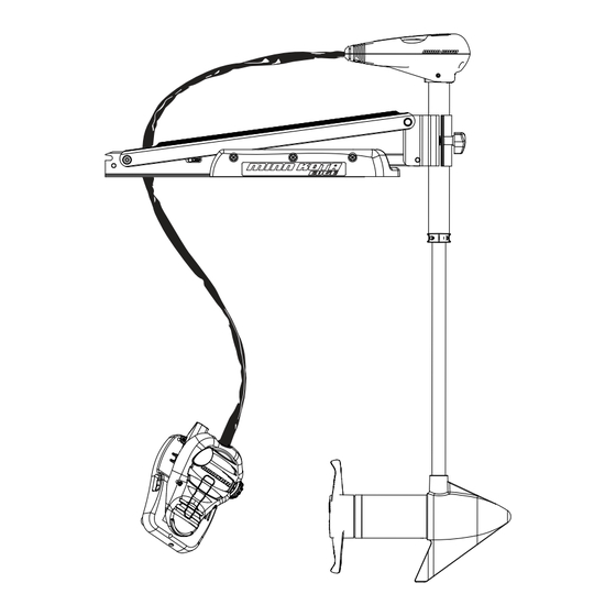
- Page 5 FEATURES Directional Indicator Mounting Bracket Latch & Door Depth Adjustment Knob Lifetime Warranty Flexible Composite Shaft Momentary Switch Rotary Speed Control Mom/Off/Con Switch Cool Quiet Power Motor Heel Block Propeller Specifications subject to change without notice. *This diagram is for reference only and may differ from your actual motor. minnkotamotors.com | 5 ©2014 Johnson Outdoors Marine Electronics, Inc.
- Page 6 3. Place the motor on top of the desired mounting location while it is in the stowed position (for stow and deploy instructions, see "Stowing and Deploying the Motor" on p. 11). 4. Verify the motor rest is positioned far enough beyond the edge of the boat so that the motor clears all obstructions while deploying and stowing the motor.
- Page 7 MOUNT INSTALLATION 5. Deploy the motor and remove the motor assembly from the mount by loosening the Steering Tension Knob and opening the door. WARNING: When raising or lowering motor, keep fi ngers clear of all hinge and pivot points and all moving parts. Depth Adjustment Knob Motor Assembly 6.
- Page 8 CAUTION: These guidelines apply to general rigging to support your Minn Kota motor. Powering multiple motors or additional electrical devices from the same power circuit may impact the recommended conductor gauge and circuit breaker size. If you are using wire longer than that provided with your unit, follow the conductor gauge and circuit breaker sizing table below.
- Page 9 • It is highly recommended that a circuit breaker or fuse be used with this trolling motor. Refer to “Conductor Gauge and Circuit Breaker Sizing Table” in the previous section to fi nd the appropriate circuit breaker or fuse for your motor. For motors requiring a 60-amp breaker, the Minn Kota MKR-19 60-amp circuit breaker is recommended. CONNECTING THE BATTERIES 12 VOLT SYSTEMS: 1.
- Page 10 MOTOR WIRING DIAGRAM NOTE: This is a universal, multi-voltage diagram. Double-check your motor's voltage for proper connections. Over-Current Protection Devices not shown in this illustration. RED+ FIVE SPEED SWITCH TERMINAL BLOCK MOM/OFF/CON SWITCH MOMENTARY SWITCH BLACK/WHITE BLACK- RED+ BATTERY 1 MOT0R BATTERY 1 BATTERY 2...
- Page 11 USING AND ADJUSTING THE MOTOR STOWING AND DEPLOYING THE MOTOR WARNING: When raising or lowering the motor, keep fi ngers clear of all hinge and pivot points and all moving parts. MOUNT FEATURES • The motor mount is designed to fold back and lock the motor fl at on the deck when not in use and to provide secure stowage for transport.
- Page 12 USING & ADJUSTING THE MOTOR ADJUSTING THE DEPTH OF THE MOTOR Depth Adjustment Knob The propeller tip must be submerged at least 12” to avoid churning or agitation of surface water. Outer Shaft 1. With the motor deployed, fi rmly grasp the outer shaft or control head and hold it steady.
- Page 13 USING & ADJUSTING THE MOTOR CONTROLLING SPEED & STEERING WITH THE FOOT PEDAL Most controls on the foot pedal are easy to operate by either foot or hand: Toe End Speed Knob Momentary Button Directional Indicator Heel End Mom/Off /Con Switch TO ADJUST MOTOR SPEED Turn the speed knob clockwise to increase speed and counter-clockwise to decrease speed.
- Page 14 7. The propeller is designed to provide weed free operation with very high effi ciency. To maintain this top performance, the leading edge of the blades must be kept smooth. If they are rough or nicked from use, restore to smooth by sanding with fi ne sandpaper.
- Page 15 AUTHORIZED SERVICE CENTERS Minn Kota has over 300 authorized service centers in the United States and Canada where you can purchase parts or get your products repaired. Please visit our Authorized Service Center page on our website to locate a service center in your area.
- Page 16 45 LBS THRU - 12 VOLT - 36”/42”/45”/50” SHA This page provides Minn Kota® WEEE compliance disassembly instructions. For more information about where you should dispose of your waste equipment for recycling and recovery and/or your European Union member state requirements, please contact your dealer or distributor from which your product was purchased.
- Page 17 PARTS LIST EDGE 45 45 LBS THRU - 12 VOLT - 36”/42”/45”/50” SHA PART PART PART ITEM QTY DESCRIPTION ITEM QTY DESCRIPTION ITEM QTY DESCRIPTION NUMBER NUMBER NUMBER 2-100-202 SEMBLY 12 V 3.25 BUSHING —LOWER 7/16” TENSION SCREW P TE...
- Page 18 Minn Kota motors are not subject to the disposal regulations EAG-VO (electric devices directive) that implements the WEEE directive. Nevertheless never dispose of your Minn Kota motor in a garbage bin but at the proper place of collection of your local town council.
- Page 19 NOTES minnkotamotors.com | 19 ©2014 Johnson Outdoors Marine Electronics, Inc.
- Page 20 Stop buying new batteries and start taking care of the ones you’ve got. Many chargers can actually damage your battery over time – creating shorter run times and shorter overall life. Digitally controlled Minn Kota chargers are designed to provide the fastest charge that protect and extend battery life.
- Page 21 EDGE MOTEUR DE PÊCHE À LA TRAÎNE MONTÉ SUR L’ÉTRAVE MANUEL DE L’UTILISATEUR...
- Page 22 REMARQUE : ne pas retourner le moteur Minn Kota au détaillant. Le détaillant n’est pas autorisé à réparer ou à remplacer cet appareil. Pour le service : communiquer avec Minn Kota au +1 (800) 227-6433; retourner le moteur au Centre de service de l’usine de Minn Kota; envoyer ou apporter le moteur à...
- Page 23 TABLE DES MATIÈRES Garantie Limitée de Deux Ans Caractéristiques 26-27 Installation du Support 28-29 Installation de la Batterie et du Câblage Gréement de l’embarcation et Installation du Produit Tableau des Dimensions de Gabarit des Conducteurs et Disjoncteurs Sélectionner une Batterie Adéquate Comment raccorder la Batterie Schéma de Câblage du Moteur 31-33...
- Page 24 Les articles achetés à l’extérieur des États-Unis doivent être retournés, port payé avec la preuve d’achat (y compris la date d’achat et le numéro de série), à tout centre de service agréé Minn Kota dans le pays de l’achat. Le service au titre de la garantie peut être obtenu en communiquant avec le centre de service agréé...
- Page 25 CARACTÉRISTIQUES Indicateur Directionnel Supports de montage Loquet et Porte Bouton de Réglage de la Profondeur Arbre composite flexible garanti à vie Commutateur momentané Contrôle des vitesses rotatives Commutateur Mom./Arrêt/Con. Moteur Cool Power Talon de blocage silencieux Hélice* Les spécifications sont sujettes à changement sans préavis. *Le schéma est fourni aux fins de référence seulement et peut différer de votre moteur actuel.
- Page 26 INSTALLATION DU SUPPORT OUTILS ET RESSOURCES NÉCESSAIRES : • Tournevis Phillips • Perceuse • Mèche de 7,144 mm (9/32”) • Clé à oeil de 11 mm (7/16 “) • Une deuxième personne pour vous aider avec l’installation 1. Avant de procéder, déterminez l’emplacement désiré pour le montage du moteur. Nous recommandons que le moteur soit monté...
- Page 27 INSTALLATION DU SUPPORT 5. Déployez le moteur et retirez l’assemblage du moteur du support en desserrant le bouton de réglage de profondeur et en ouvrant la porte. AVERTISSEMENT! : Lorsque vous remontez ou abaissez le moteur, gardez vos doigts loin de toutes charnières et points de pivot et de toutes pièces mobiles.
- Page 28 é. Les spécifi cations suivantes sont seulement des lignes directrices générales: MISE EN GARDE!: ces lignes directrices s’appliquent au gréement général pour soutenir le moteur de Minn Kota. L’alimentation de multiples moteurs ou d’autres appareils électriques, à partir du même circuit d’alimentation, peut infl uer sur le gabarit de conducteurs et le dimensionnement des disjoncteurs recommandé.
- Page 29 Si vous utilisez une batterie à manivelle pour démarrer un moteur hors-bord à essence, nous vous recommandons d’utiliser des batteries marines à décharge profonde séparées pour votre propulseur électrique Minn Kota.
- Page 30 SCHÉMA DE CÂBLAGE DU MOTEUR REMARQUE: Il s’agit d’un schéma multi-tensions universel. Vérifier à nouveau la tension du moteur afin de vous assurer que les raccordements sont appropriés. Les dispositifs de protection contre la surintensité ne figurent pas dans cette illustration. ROUGE+ INTERRUPTEUR A CING VIT DE CONNEXIONS...
- Page 31 CARACTÉRISTIQUES DU SUPPORT • Le support Edge est conçu pour se replier et verrouiller le moteur à plat sur le pont, lorsqu’il n’est pas utilisé, et pour fournir un arrimage sûr pour le transport.
- Page 32 UTILISATION ET RÉGLAGE DU MOTEUR POUR AJUSTER LA PROFONDEUR DU MOTEUR Bouton de Réglage de la Profondeur L’extrémité de l’hélice doit être immergée à au moins 30,5 cm (12 po), afi n d’éviter de remuer ou d’agiter l’eau à la surface. Arbre 1.
- Page 33 UTILISATION ET RÉGLAGE DU MOTEUR CONTRÔLE DE VITESSE ET DE DIRECTION AVEC LA PÉDALE La plupart des contrôles sur la pédale sont faciles à faire fonctionner soit avec la main ou le pied : Extrémité des orteils Bouton des vitesses Bouton provisoire Indicateur Extrémité...
- Page 34 SERVICE ET ENTRETIEN REMPLACEMENT DE L’HÉLICE OUTILS ET RESSOURCES NÉCESSAIRES: Hélice • Clé à oeil de 11 mm (7/16 “) Fente à l’extrémité • Tournevis (facultatif) Écrou de l’hélice Rondelle MISE EN GARDE: Débrancher le moteur de la batterie avant d’eff ectuer tout travail ou entretien sur l’hélice.
- Page 35 FOIRE AUX QUESTIONS Notre site Web présente FAQ visant à répondre à toutes vos questions au sujet des produits Minn Kota. Veuillez visiter le site Web minnkotamotors.com, puis cliquer sur « Foire aux questions » pour trouver réponse à vos questions.
- Page 36 EDGE 45 POUSSÉE DE 45 LB - 12 VOLTS - ARBRE 36/42/45/50 PO Cette page fournit les consignes de dépose de Minn Kota® en conformité avec la directive DEEE. Pour de l’information supplémentaire sur l’endroit où vous pouvez vous débarrasser de l’équipement usagé pour le recyclage et la récupération et/ou sur les exigences de votre État membre de l’Union européenne, veuillez...
- Page 37 LISTES DES PIÈCES EDGE 45 POUSSÉE DE 45 LB - 12 VOLTS - ARBRE 36/42/45/50 PO NUMÉRO NUMÉRO NUMÉRO ART. QTÈ DESCRIPTION ART. QTÈ DESCRIPTION ART. QTÈ DESCRIPTION DE PIÈCE DE PIÈCE DE PIÈCE SEMB GE DE BR 2263510 BOULON — ÉPAULE, AI ENTR OISE —...
- Page 38 Les moteurs Minn Kota ne sont pas soumis à la réglementation concernant l’élimination VGE-VO (directive pour les dispositifs électriques), qui transpose la directive DEEE. Néanmoins, ne jamais jeter le moteur Minn Kota dans une poubelle, mais plutôt à l’endroit approprié où s’eff ectue la collecte, recommandé par le conseil municipal local.
- Page 39 REMARQUES minnkotamotors.com | 39 ©2014 Johnson Outdoors Marine Electronics, Inc.
- Page 40 à la longue, pouvant entraîner une autonomie réduite et une durée de vie plus courte. Les chargeurs Minn Kota à commande numérique assurent une charge rapide pour une protection et une durée de vie prolongée.