Table des Matières
Publicité
Les langues disponibles
Les langues disponibles
Liens rapides
Publicité
Chapitres
Table des Matières
Dépannage

Manuels Connexes pour MINN KOTA EDGE Serie


Sommaire des Matières pour MINN KOTA EDGE Serie
- Page 1 EDGE BOW-MOUNT TROLLING MOTOR Owner's Manual...
- Page 2 THANK YOU Thank you for choosing Minn Kota. We believe that you should spend more time fishing and less time positioning your boat. That’s why we build the smartest, toughest, most intuitive trolling motors on the water. Every aspect of a Minn Kota trolling motor is thought out and rethought until it’s good enough to bear our name.
-
Page 3: Table Des Matières
Table Of CONTeNTs SAFETY CONSIDERATIONS ....................4 TWO-YEAR LIMITED WARRANTY ..................5 KNOW YOUR BOAT ......................6 FEATURES ........................7 INSTALLATION......................8 Mount Installation ....................8 BATTERY & WIRING INSTALLATION ................11 Boat Rigging & Product Installation ..............11 Conductor Gauge and Circuit Breaker Sizing Table..........11 Selecting the Correct the Batteries ............... -
Page 4: Safety Considerations
WARNING You are responsible for the safe and prudent operation of your vessel. We have designed your Minn Kota product to be an accurate and reliable tool that will enhance boat operation and improve your ability to catch fish. This product does not relieve you from the responsibility for safe operation of your boat. - Page 5 Products purchased outside of the U.S. must be returned prepaid with proof of purchase (including the date of purchase and serial number) to any Authorized Minn Kota Service Center in the country of purchase.
-
Page 6: Know Your Boat
KNOW YOUR bOaT Port Port Starboard Starboard Inboard Inboard Outboard Outboard Keel Keel Port Port Starboard Starboard Gunwale Gunwale Transom Transom Stern Stern Gunwale Gunwale Stern Stern Hull Hull 6 | minnkotamotors.com ©2020 Johnson Outdoors Marine Electronics, Inc. -
Page 7: Features
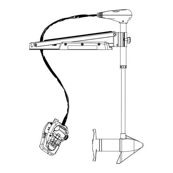
feaTURes Directional Indicator Directional Indicator Latch & Door Latch & Door Depth Adjustment Knob Depth Adjustment Knob Motor Rest Motor Rest Lifetime Warranty Lifetime Warranty Flexible Composite Shaft Flexible Composite Shaft Momentary Momentary Switch Switch Rotary Speed Control Rotary Speed Control Mom/Off/Con Switch Mom/Off/Con Switch Cool Quiet... -
Page 8: Installation
INsTallaTION MOUNTING CONSIDERATIONS Please review the following guidelines before beginning the installation of the Edge: The Motor should be mounted as close to the centerline or keel NOTICE: We recommend that you have another person of the boat as possible when it is deployed. help with this installation. - Page 9 INSTALLATION Deploy the motor and remove the Motor Assembly from the Mount by loosening the Depth Adjustment Knob and opening the Latch & Door. Latch & Latch & Door Door Depth Depth Adjustment Adjustment Motor Assembly Motor Assembly Knob Knob Position the Mount again in the stowed position.
- Page 10 INSTALLATION Reinstall the Motor Rest using the six original ¼” Phillips Screws. Reinstall the Motor Assembly into the Mount and securely tighten the Depth Adjustment Knob. Motor Rest Motor Rest Latch & Door Latch & Door Mounting Bracket Mounting Bracket Depth Depth Motor Assembly...
-
Page 11: Battery & Wiring Installation
CAUTION These guidelines apply to general rigging to support your Minn Kota motor. Powering multiple motors or additional electrical devices from the same power circuit may impact the recommended conductor gauge and circuit breaker size. If you are using wire longer than that provided with your unit, follow the conductor gauge and circuit breaker sizing table below. -
Page 12: Selecting The Correct The Batteries
(flooded, AMG or GEL). Lithium Ion batteries maintain higher voltages for longer periods of time than lead acid. Therefore, running a Minn Kota trolling motor at speeds higher than 85% for a prolonged period could cause permanent damage to the motor. -
Page 13: Connecting The Batteries
CONNECTING THE BATTERIES The negative (-) connection must be connected to the negative terminal of the same battery that the trolling motor negative lead connects to. In the diagrams below this battery is labeled “Low Side” Battery. Connecting to any other trolling motor battery will input positive voltage into the “ground”... -
Page 14: Connecting The Batteries In Series
CONNECTING THE BATTERIES IN SERIES CONNECTING THE BATTERIES IN SERIES (IF REQUIRED FOR YOUR MOTOR) 24-Volt Systems Two 12-volt batteries are required. The batteries must be wired in +24 Volts to trolling motor +24 Volts to trolling motor positive (or circuit breaker) positive (or circuit breaker) series, only as directed in the wiring diagram, to provide 24 volts. -
Page 15: Motor Wiring Diagram
MOTOR WIRING DIaGRaM EDGE The following Motor Wiring Diagram applies to all Edge Foot Control models. Five Speed Switch Terminal Block (CONNECTOR 1/4 MALE TAB QD) Mom/Off/Con Switch Momentary Switch Black/white Black- Red+ Battery 1 Motor Battery 1 Battery 2 NOTICE: This is a multi-voltage diagram. -
Page 16: Using & Adjusting The Motor
UsING & aDJUsTING THe MOTOR MOUNT FEATURES Become familiar with the features of the motor to maximize the capabilities this product offers. Motor Shaft Motor Shaft Rope Stow Slot Rope Stow Slot Lower Unit Lower Unit Yoke Yoke Motor Rest Motor Rest Pull Grip Pull Grip... -
Page 17: Stowing And Deploying The Motor
USING & ADJUSTING THE MOTOR STOWING AND DEPLOYING THE MOTOR WARNING When stowing or deploying the motor, keep fingers clear of all hinge and pivot points and all moving parts. Practice proper ergonomics when stowing and deploying the motor to prevent injury. WARNING Moving the motor creates a variety of pinch points. -
Page 18: Motor Adjustments
ADJUSTING THE DEPTH OF THE MOTOR MOTOR ADJUSTMENTS Adjusting the Depth of the Motor When setting the depth, be sure the top of the motor is submerged at least 12” to avoid churning or agitation of surface water. The propeller must be completely submerged. With the motor deployed, firmly grasp the Outer Shaft or Control Head and hold it steady. -
Page 19: Using The Foot Pedal
UsING THe fOOT PeDal CONTROLLING SPEED & STEERING WITH THE FOOT PEDAL Most controls on the Foot Pedal are easy to operate by either foot or hand. Speed Knob Speed Knob Toe End Toe End Directional Directional Indicator Indicator Momentary Momentary Heel End Heel End... -
Page 20: Foot Pedal Adjustments
USING THE FOOT PEDAL CAUTION Route the Foot Pedal Cable neatly to minimize tripping hazards. Practice proper ergonomics when operating the Foot Pedal to avoid fatigue and prevent injury. FOOT PEDAL ADJUSTMENTS Adjusting the Steering Cable The steering cable tension is pre-set at the factory but will, through normal use, need occasional adjustment. Adjust the tension of the cables by turning the cable Cable Tension Cable Tension... -
Page 21: Service & Maintenance
seRVICe & MaINTeNaNCe PROPELLER REPLACEMENT TOOLS AND RESOURCES REQUIRED • 1/2” Open End Wrench • 9/16” Open End Wrench • Screwdriver (70 lbs thrust or lower) (80 lbs thrust or higher) INSTALLATION Disconnect the motor from all sources of power prior to Armature Armature Drive Pin... -
Page 22: General Maintenance
GENERAL MAINTENANCE GENERAL MAINTENANCE • After use, the entire motor should be rinsed with freshwater, then wiped down with a cloth dampened with an aqueous based silicone spray. • The composite shaft requires periodic cleaning and lubrication for proper retraction and deployment. A coating of an aqueous based silicone spray will improve operation. -
Page 23: For Further Troubleshooting And Repair
Authorized Service Centers Minn Kota has over 800 authorized service providers in the United States and Canada where you can purchase parts or get your products repaired. Please visit our Authorized Service Center page on our website to locate a service provider in your area. -
Page 24: Compliance Statements
Minn Kota motors are not subject to the disposal regulations EAG-VO (electric devices directive) that implements the WEEE directive. Nevertheless never dispose of your Minn Kota motor in a garbage bin but at the proper place of collection of your local town council. - Page 25 COMPLIANCE STATEMENTS FCC COMPLIANCE This device complies with Part 15 of the FCC rules. Operation is subject to the following two conditions: This device may not cause harmful interference. This device must accept any interference that may be received, including interference that may cause undesired operation. Changes or modifi cations not expressly approved by Johnson Outdoors Marine Electronics, Inc.
-
Page 26: Parts Diagram & Parts List
PaRTs DIaGRaM & PaRTs lIsT EDGE 45 - 45 LBS THRUST - 12 VOLT - 36”/42”/45”/50” SHAFT This page provides Minn Kota ® WEEE compliance disassembly instructions. For more information about where you should dispose of your waste equipment for recycling and recovery and/or your European Union member state requirements, please contact your dealer or distributor from which your product was purchased. - Page 27 PARTS DIAGRAM & PARTS LIST Foot Pedal & Control Head Parts List Assembly Part # Description Notes Quantity 2992126 FOOT PEDAL ASM, EDGE *36"* 2992130 FT PEDAL ASM, EDGE w/PLUG *45"* *W/O MOUNT* *W/PLUG* Item Part # Description Notes Quantity 2260216 COVER,CTRL BOX, EDGE 2372100...
- Page 28 PARTS DIAGRAM & PARTS LIST Item Part # Description Notes Quantity 2266412 SWITCH PLATE, FT PEDAL 2332103 SCREW-#6-20 X 3/8 THD*(SS) 2261208 WIRE HARNESS, A/T FT. PEDAL 2267505 CABLE ASSY-RIGHT (5') 2267515 CABLE ASSY-LEFT (5') 2265430 CABLE JACKET (5') AT MODEL 2265115 BOOT-FOOT PEDAL BASE 2372100...
- Page 29 PARTS DIAGRAM & PARTS LIST EDGE 45 MOTOR Motor Parts Diagram minnkotamotors.com | 29 ©2020 Johnson Outdoors Marine Electronics, Inc.
- Page 30 PARTS DIAGRAM & PARTS LIST Motor Parts List Assembly Part # Description Notes Quantity 2069285 MTR ASY 12V 3.25 SC FW 45 *36"* *42"* 2069286 MTR ASY 12V 3.25 SC FW 45 *45"* *50"* 2992015 TUBE W/BEARING RACE ASSY *36"* *42"* 2992012 TUBE W/BEARING RACE ASSY *45"*...
- Page 31 PARTS DIAGRAM & PARTS LIST Item Part # Description Notes Quantity 725-035 PAPER TUBE - SEAL BORE 640-002M LEADWIRE BLK 10 AWG 52 GPT *36”* 640-005 LEADWIRE BLK 10 AWG 57 GPT *45"* *50"* 640-005M LEADWIRE BLK 10 AWG 57 GPT *45"* *W/O MOUNT* 640-112M LEADWIRE RED 10 AWG 53 GPT...
- Page 32 PARTS DIAGRAM & PARTS LIST PARTS DIAGRAM & PARTS LIST PARTS DIAGRAM & PARTS LIST EDGE 45 MOUNT Mount Parts Diagram 32 | minnkotamotors.com ©2020 Johnson Outdoors Marine Electronics, Inc.
- Page 33 PARTS DIAGRAM & PARTS LIST PARTS DIAGRAM & PARTS LIST PARTS DIAGRAM & PARTS LIST Mount Parts List Assembly Part # Description Notes Quantity 2991646 MNT ASM EDGE FW SHORT 2991647 MNT ASM EDGE FW LONG *50"* 2994838 BAG ASSY-(BOLTS,NUTS,WASHERS) 2993811 LATCH STRAP ASSEMBLY STD 2991829...
- Page 34 PARTS DIAGRAM & PARTS LIST PARTS DIAGRAM & PARTS LIST PARTS DIAGRAM & PARTS LIST Item Part # Description Quantity Notes 2263505 BOLT 3/8-16 UNC X 4.25" HEXHD 2263114 NUT-NYLOCK JAM 3/8-16 UNC 2261892 HINGE BASE EXTRUSION,FW 2261897 HINGE DOOR EXTRUSION,FW 2260905 KNOB-SOFT GRIP,HG/DR,ZNC 2261728...
- Page 35 NOTes minnkotamotors.com | 35 ©2020 Johnson Outdoors Marine Electronics, Inc.
- Page 36 Stop buying new batteries and start taking care of the ones you’ve got. Many chargers can actually damage your battery over time – creating shorter run times and shorter overall life. Digitally controlled Minn Kota chargers are designed to provide the fastest charge that protect and extend battery life.
- Page 37 EDGE MOTEUR DE PÊCHE À LA TRAÎNE MONTÉ SUR L’ÉTRAVE Manuel du Propriétaire...
- Page 38 à amarrer votre embarcation. C’est pourquoi nous construisons les moteurs de pêche à la traîne les plus intelligents, les plus solides et les plus faciles à utiliser. Chaque aspect d’un moteur de pêche à la traîne Minn Kota est réfléchi et étudié jusqu’à ce qu’il soit digne de porter notre nom.
- Page 39 Table Des MaTIÈRes CONSIGNES DE SÉCURITÉ .................... 40 GARANTIE LIMITÉE DE DEUX ANS .................. 41 CONNAISSEZ VOTRE BATEAU ..................42 CARACTÉRISTIQUES ....................43 INSTALLATION......................44 Installation du support ..................44 INSTALLATION DE LA BATTERIE ET DU CÂBLAGE ............... 47 Gréement de l’embarcation et installation du produit ..........47 Tableau des dimensions de gabarit des conducteurs et disjoncteurs ......
-
Page 40: Consignes De Sécurité
à la navigation et toujours exercer une veille permanente afin de pouvoir réagir au fur et à mesure que les situations se présentent. Vous devez toujours être prêt à reprendre le contrôle manuel de votre bateau. Apprenez à utiliser votre Minn Kota dans une zone exempte de dangers et d’obstacles. -
Page 41: Garantie Limitée De Deux Ans
Les articles achetés à l’extérieur des États-Unis doivent être retournés, port payé avec la preuve d’achat (y compris la date d’achat et le numéro de série), à tout centre de service agréé Minn Kota dans le pays de l’achat. Le service au titre de la garantie peut être obtenu en communiquant avec le centre de service agréé... -
Page 42: Connaissez Votre Bateau
CONNaIsseZ VOTRe baTeaU Étrave Bâbord Tribord En-bord Hors-bord Quille Bâbord Tribord Plat-bord Tableau Arrière Stern Plat-bord Étrave Poupe Coque 42 | minnkotamotors.com ©2020 Johnson Outdoors Marine Electronics, Inc. -
Page 43: Caractéristiques
CaRaCTÉRIsTIQUes Indicateur Indicateur directionnel directionnel Support de Support de montage montage Loquet et porte Loquet et porte Bouton de réglage Bouton de réglage de la profondeur de la profondeur Arbre composite flexible Arbre composite flexible garanti à vie garanti à vie Commutateur Commutateur momentané... -
Page 44: Installation
INsTallaTION FACTEURS DE MONTAGE Révisez les directives suivantes avant de commencer l’installation AVIS : Nous vous conseillons de vous faire aider d’une du Edge : deuxième personne pour cette installation. Le moteur devrait être monté aussi près que possible de la quille ou de l’axe central du bateau lorsqu’il est déployé. - Page 45 INSTALLATION Déployez le moteur et retirez l’assemblage du moteur du support en desserrant le bouton de réglage de la profondeur et en ouvrant la porte. Loquet et Loquet et porte porte Bouton de Bouton de réglage de la réglage de la Ensemble moteur Ensemble moteur profondeur...
- Page 46 INSTALLATION Déterminez la structure des trous de montage que vous souhaitez utiliser. En utilisant les trous de montage Boulonnage 1 Boulonnage 1 dans le support comme modèle, marquez le pont supérieur du bateau avec un crayon ou un outil de marquage semblable.
-
Page 47: Installation De La Batterie Et Du Câblage
ATTENTION Ces lignes directrices s’appliquent au gréement général pour soutenir le moteur de Minn Kota. L’alimentation de multiples moteurs ou d’autres appareils électriques, à partir du même circuit d’alimentation, peut infl uer sur le gabarit de conducteurs et le dimensionnement des disjoncteurs recommandé. -
Page 48: Comment Sélectionner Les Batteries Adéquates
Utilisation de chargeurs à c.c. ou alternateurs Votre moteur de pêche à la traîne Minn Kota peut être conçu avec un fil de masse interne pour réduire les interférences avec d’autres sonars. La plupart des systèmes de charge alternateurs ne tiennent pas compte de ce fil de masse et connectent les bornes négatives des batteries du moteur de pêche à... -
Page 49: Connexion Des Batteries
à la traîne Votre moteur Minn Kota, les composants électroniques de votre bateau ou votre bateau peuvent subir des dommages importants si de mauvaises connexions ont été effectuées entre les batteries de votre moteur de pêche à la traîne et un autre système de batterie. Minn Kota recommande d’utiliser un système de batterie exclusif pour votre propulseur électrique. -
Page 50: Brancher Les Batteries En Série
CONNEXION DES BATTERIES EN SÉRIE BRANCHER LES BATTERIES EN SÉRIE (SI REUIS POUR VOTRE MOTEUR) Systèmes de 24 Volts 24 Volts à Moteur à la Traîne 24 Volts à Moteur à la Traîne Pour un moteur de Pour un moteur de Deux batteries de 12 volts sont nécessaires. -
Page 51: Schéma De Câblage Du Moteur
sCHÉMa De CÂblaGe DU MOTeUR SCHÉMA DE CÂBLAGE DU MOTEUR Le schéma de câblage du moteur suivant s’applique à tous les modèles de contrôle à pédale Edge. Rouge Interrupteur A Cinq Vitesses Plaquette De Connexions (CONNECTOR 1/4 Interrupteur MALE TAB QD) Mom/hc/con Noir/blanc Interrupteur... -
Page 52: Utilisation Et Réglage Du Moteur
UTIlIsaTION eT RÉGlaGe DU MOTeUR CARACTÉRISTIQUES DU SUPPORT Prenez connaissance des fonctionnalités du moteur afin de maximiser les capacités qu’offre ce produit. Arbre du Arbre du moteur moteur Fente de Fente de rangement rangement de la corde de la corde Unité... -
Page 53: Arrimage Et Déploiement Du Moteur
UTILISATION ET RÉGLAGE DU MOTEUR ARRIMAGE ET DÉPLOIEMENT DU MOTEUR AVERTISSEMENT Lorsque vous remontez ou abaissez le moteur, gardez vos doigts loin de toutes charnières et tous points de pivot ainsi que de toutes pièces mobiles. Utilisez de bonnes pratiques ergonomiques lorsque vous arrimez et déployez le moteur afin de prévenir les blessures. AVERTISSEMENT Déplacer le moteur crée une variété... -
Page 54: Ajustements Du Moteur
RÉGLAGE DE LA PROFONDEUR DU MOTEUR AJUSTEMENTS DU MOTEUR Réglage de la profondeur du moteur Au moment du réglage de la profondeur, assurez-vous que le dessus du moteur est immergé à au moins 12 po (30,5 cm) afin d’éviter de faire tourbillonner ou d’agiter l’eau à la surface. L’hélice doit être complètement submergée. Une fois le moteur en position immergée, empoignez l’arbre externe ou la tête de contrôle et maintenez- Bouton de... -
Page 55: Utilisation De La Pédale
UTIlIsaTION De la PÉDale CONTRÔLE DE LA VITESSE ET DE LA DIRECTION AVEC LA PÉDALE La plupart des contrôles sur la pédale sont faciles à faire fonctionner avec la main ou le pied. Extrémité Extrémité Bouton des Bouton des des orteils des orteils vitesses vitesses... -
Page 56: Ajustements De La Pédale
UTILISATION DE LA PÉDALE Pour faire fonctionner le moteur en marche arrière Le moteur pousse toujours dans la direction qui s’affiche sur l’indicateur. Vous pouvez inverser la direction du moteur en tournant le moteur à 180° à partir de l’avant. ATTENTION Acheminez le câble de pédale proprement pour réduire les risques de trébuchement. -
Page 57: Service Et Entretien
seRVICe eT eNTReTIeN REMPLACEMENT DE L’HÉLICE OUTILS ET RESSOURCES NÉCESSAIRES • Clé ouverte 1/2 po (12,7 mm) • Clé ouverte 9/16 po (14,3 mm) • Tournevis (poussée de 70 lb/27 kg ou moins) (poussée de 80 lb/36 kg ou moins) INSTALLATION Débranchez le moteur de toute source d’alimentation Arbre... -
Page 58: Entretien Général
ENTRETIEN GÉNÉRAL ENTRETIEN GÉNÉRAL • Après l’utilisation, il faut rincer complètement le moteur avec de l’eau douce. Cette série de moteurs ne peut pas être exposée à l’eau salée. • L’arbre en composite doit être régulièrement nettoyé et lubrifié pour une bonne rétraction et un bon déploiement. Une vaporisation de silicone à... -
Page 59: Pour D'autres Services De Dépannage Et De Réparation
Foire Aux Questions Notre site Web met à votre disposition des FAQ visant à répondre à toutes vos questions au sujet des produits Minn Kota. Veuillez visiter le site Web minnkotamotors.com... -
Page 60: Déclarations De Conformité
Les moteurs Minn Kota ne sont pas soumis à la réglementation concernant l’élimination VGE-VO (directive pour les dispositifs électriques), qui transpose la directive DEEE. Néanmoins, ne jamais jeter le moteur Minn Kota dans une poubelle, mais plutôt à l’endroit approprié où s’effectue la collecte, recommandé par le conseil municipal local. - Page 61 DÉCLARATIONS DE CONFORMITÉ CONFORMITÉ FCC Cet appareil est conforme à la section 15 des règles de la FCC. Son fonctionnement est soumis aux deux conditions suivantes : Ce dispositif ne doit pas causer d’interférences nuisibles. Cet appareil doit accepter toute interférence qui peut être reçue, y compris les interférences susceptibles de perturber son fonctionnement.
-
Page 62: Schéma Des Pièces Et Liste Des Pièces
Des PIÈCes eT lIsTe Des PIÈCes EDGE 45 - POUSSÉE DE 45 LB - 12 VOLTS - ARBRE 36/42/45/50 PO Cette page fournit les consignes de dépose de Minn Kota ® en conformité avec la directive DEEE. Pour de l’information supplémentaire sur l’endroit où... - Page 63 SCHÉMA DES PIÈCES ET LISTE DES PIÈCES Liste des pièces de la pédale et la tête de contrôle Ensemble Nº de Pièce Description Remarques Quantité 2992126 FOOT PEDAL ASM, EDGE *36 po (91 cm)* 2992130 FT PEDAL ASM, EDGE w/PLUG *45 po (114 cm)* *SANS SUPPORT* *AVEC FICHE* Nº...
- Page 64 SCHÉMA DES PIÈCES ET LISTE DES PIÈCES Nº d’Article Nº de Pièce Description Remarques Quantité 2301310 SCREW-#8-18 X 1/2 (SS)* 2254031 SWITCH-MOM/OFF/COM 2266412 SWITCH PLATE, FT PEDAL 2332103 SCREW-#6-20 X 3/8 THD*(SS) 2261208 WIRE HARNESS, A/T FT. PEDAL 2267505 CABLE ASSY-RIGHT (5') 2267515 CABLE ASSY-LEFT (5') 2265430...
- Page 65 SCHÉMA DES PIÈCES ET LISTE DES PIÈCES MOTEUR EDGE 45 Schéma des Pièces du Moteur minnkotamotors.com | 65 ©2020 Johnson Outdoors Marine Electronics, Inc.
- Page 66 SCHÉMA DES PIÈCES ET LISTE DES PIÈCES Liste des Pièces du Moteur Ensemble Nº de Pièce Description Remarques Quantité 2069285 MTR ASY 12V 3.25 SC FW 45 *36 po (91 cm)* *42 po (106 cm)* 2069286 MTR ASY 12V 3.25 SC FW 45 *45 po (114 cm)* *50 po (127 cm)* 2992015 TUBE W/BEARING RACE ASSY...
- Page 67 SCHÉMA DES PIÈCES ET LISTE DES PIÈCES Nº d’Article Nº de Pièce Description Remarques Quantité 725-035 PAPER TUBE - SEAL BORE 640-002M LEADWIRE BLK 10 AWG 52 GPT *36 po (91 cm)* 640-005 LEADWIRE BLK 10 AWG 57 GPT *45 po (114 cm)* *50 po (127 cm)* 640-005M LEADWIRE BLK 10 AWG 57 GPT *45 po (114 cm)* *SANS SUPPORT*...
- Page 68 SCHÉMA DES PIÈCES ET LISTE DES PIÈCES SCHÉMA DES PIÈCES ET LISTE DES PIÈCES SCHÉMA DES PIÈCES ET LISTE DES PIÈCES SUPPORT EDGE 45 Schéma des Pièces du Support 68 | minnkotamotors.com ©2020 Johnson Outdoors Marine Electronics, Inc.
- Page 69 SCHÉMA DES PIÈCES ET LISTE DES PIÈCES SCHÉMA DES PIÈCES ET LISTE DES PIÈCES SCHÉMA DES PIÈCES ET LISTE DES PIÈCES Liste des Pièces du Support Ensemble Nº de Pièce Description Remarques Quantité 2991646 MNT ASM EDGE FW SHORT 2991647 MNT ASM EDGE FW LONG *50 po (127 cm)* 2994838...
- Page 70 SCHÉMA DES PIÈCES ET LISTE DES PIÈCES SCHÉMA DES PIÈCES ET LISTE DES PIÈCES SCHÉMA DES PIÈCES ET LISTE DES PIÈCES Nº d’Article Nº de Pièce Description Remarques Quantité 2263505 BOLT 3/8-16 UNC X 4.25" HEXHD 2263114 NUT-NYLOCK JAM 3/8-16 UNC 2261892 HINGE BASE EXTRUSION,FW 2261897...
- Page 71 ReMaRQUes minnkotamotors.com | 71 ©2020 Johnson Outdoors Marine Electronics, Inc.
- Page 72 à la longue, pouvant entraîner une autonomie réduite et une durée de vie plus courte. Les chargeurs Minn Kota à commande numérique assurent une charge rapide pour une protection et une durée de vie prolongée.