Publicité
Liens rapides
–
INSTALLATION &
OPERATION
MANUAL
–
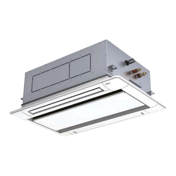
INDOOR UNITS SYSTEM FREE
2 - way cassette
MODELS
RCD-(0.8-6.0)FSR
EN
INSTALLATION AND OPERATION MANUAL
ES
MANUAL DE INSTALACIÓN Y FUNCIONAMIENTO
DE
INSTALLATIONS- UND BETRIEBSHANDBUCH
FR
MANUEL D'INSTALLATION ET DE FONCTIONNEMENT
IT
MANUALE D'INSTALLAZIONE E D'USOI
PT
MANUAL DE INSTALAÇÃO E DE FUNCIONAMENTO
DA
INSTALLATIONS- OG BETJENINGSVEJLEDNING
NL
INSTALLATIE- EN BEDIENINGSHANDLEIDING
SV
INSTALLATION- OCH DRIFTHANDBOK
EL
ΕΓΧΕΙΡΙΔΙΟ ΕΓΚΑΤΑΣΤΑΣΗΣ ΚΑΙ ΛΕΙΤΟΥΡΓΙΑΣ
PMML0549 rev.1 - 02/2021 - A10761230A
Publicité

Manuels Connexes pour Hitachi RCD-08FSR


Sommaire des Matières pour Hitachi RCD-08FSR
- Page 1 – INSTALLATION & OPERATION MANUAL – INDOOR UNITS SYSTEM FREE 2 - way cassette MODELS RCD-(0.8-6.0)FSR INSTALLATION AND OPERATION MANUAL MANUAL DE INSTALACIÓN Y FUNCIONAMIENTO INSTALLATIONS- UND BETRIEBSHANDBUCH MANUEL D’INSTALLATION ET DE FONCTIONNEMENT MANUALE D’INSTALLAZIONE E D’USOI MANUAL DE INSTALAÇÃO E DE FUNCIONAMENTO INSTALLATIONS- OG BETJENINGSVEJLEDNING INSTALLATIE- EN BEDIENINGSHANDLEIDING INSTALLATION- OCH DRIFTHANDBOK...
- Page 3 Specifikationerna i den här handboken kan ändras utan föregående meddelande för att Hitachi ska kunna leverera de senaste innovationerna till kunderna. Vi på Hitachi gör allt vi kan för att se till att alla specifikationer stämmer, men vi har ingen kontroll över tryckfel och kan därför inte hållas ansvariga för den typen av fel.
- Page 4 τελευταίες καινοτομίες στους πελάτες της. Αν και έχει γίνει κάθε προσπάθεια προκειμένου να εξασφαλιστεί ότι οι προδιαγραφές είναι σωστές, η Hitachi δεν μπορεί να ελέγξει τα τυπογραφικά λάθη και, ως εκ τούτου, δεν φέρει καμία ευθύνη για αυτά τα λάθη.
- Page 5 AT T E N T I O N This product shall not be mixed with general house waste at the end of its life and it shall be retired according to the appropria- ted local or national regulations in a environmentally correct way. Due to the refrigerant, oil and other components contained in Air Conditioner, its dismantling must be done by a professional installer according to the applicable regulations.
- Page 6 Π Ρ Ο Σ Ο Χ Η Σημαίνει ότι το προϊόν δεν θα πρέπει να αναμιχθεί με τα διάφορα οικιακά απορρίμματα στο τέλος του κύκλου ζωής του και θα πρέπει να αποσυρθεί σύμφωνα με τους κατάλληλους τοπικούς ή εθνικούς κανονισμούς και με τρόπο φιλικό προς το...
- Page 7 R 3 2 English VORSICHT WA R N I N G Dieses auf dem Gerät angezeigte Symbol zeigt an, dass dieses Gerät ein entzündbares Kältemittel verwendet. Bei einem Kältemit- BURST HAZARD telaustritt besteht die Gefahr der Entzündung, wenn das Kältemittel Do not allow air or any gas mixture containing oxygen into refriger- in Kontakt mit einer äußeren Zündquelle kommt.
- Page 8 R 3 2 AVVERTENZA WAARSCHUWING Per ulteriori informazioni, consultare il Manuale d’installazione e Dit symbool op het apparaat geeft aan dat het apparaat is gevuld d’uso. met R32, een geurloos ontvlambaar koelmiddel met een lage brandsnelheid (klasse A2L volgens ISO 817). Als het koelmiddel lekt, kan het ontbranden wanneer het in contact komt met een ex- Português terne ontstekingsbron.
- Page 9 R 3 2 Eesti ΠΡΟΣΟΧΗ H O I AT U S Αυτό το σύμβολο που εμφανίζεται στη μονάδα δείχνει ότι υπάρχουν σχετικές πληροφορίες στο εγχειρίδιο λειτουργίας και/ή στο εγχειρίδιο LÕHKEMISOHT εγκατάστασης. Ärge laske jahutussüsteemi (s.o torustikku) õhku või gaasisegu, mis sisaldab hapnikku. ΠΡΟΣΟΧΗ...
- Page 10 R 3 2 Română UZMANĪBU AV E R T I S M E N T Šis uz ierīces redzamais simbols norāda, ka ar šo ierīci drīkst rīkoties tikai pilnvarots servisa personāls, atsaucoties uz uzstādīšanas PERICOL DE DEFLAGRAȚIE rokasgrāmatu. Nu permiteți pătrunderea aerului sau oricărui amestec de gaz care conține oxigen în ciclul agentului frigorific (adică...
- Page 11 CD-ROM fehlen oder nicht lesbar sein sollte, required for the correct installation of the system is setzen Sie sich bitte mit Ihrem Hitachi-Händler oder included. If this is not the case, contact your distributor. Vertragspartner in Verbindung.
- Page 12 é providenciada num CD-ROM, fornecido juntamente com a unidade exterior. Contacte o seu Unité intérieure Unité extérieure distribuidor ou revendedor Hitachi, caso o CD-ROM Manuel d’installation esteja em falta ou seja ilegível. CD-ROM Manuel •...
- Page 13 Aanvullende informatie over het gekochte product is beschikbaar op een cd-rom, die wordt meegeleverd met de buitenunit. Als deze cd-rom ontbreekt of niet Eλλhnika leesbaar is, neem dan contact op met uw Hitachi- ΚΙΝΔΥΝΟΣ ΕΚΡΗΞΗΣ distributeur. Ο συμπιεστής πρέπει να έχει σταματήσει προτού αφαιρέσετε...
- Page 14 Проверете дали цялата информация, необходима külge kinnitatud CD-ROMilt. Kui CD-ROM on kadunud за правилния монтаж на инсталацията е включена в või ei ole loetav, võtke palun ühendust Hitachi ръководствата за вътрешните и външните тела. Ако edasimüüja või turustajaga. не е включена, свържете се с вашия дистрибутор.
- Page 15 Jei trūksta kompaktinio disko arba Ellenkező esetben forduljon a forgalmazóhoz. jo negalima perskaityti, kreipkitės į savo Hitachi atstovą arba platintoją. Beltéri egység Kültéri egység •...
- Page 16 можно найти в комплекте с наружным блоком. dotycząca klimatyzatorów i pomp ciepła z obsługi Если компакт-диск отсутствует или он не читается, czynnikiem chłodniczym R32, zgodna z normą обратитесь к дилеру или дистрибьютору Hitachi. IEC 60335-2-40:2018 • ВНИМАТЕЛЬНО ПРОЧИТАЙТЕ РУКОВОДСТВА И ФАЙЛЫ НА КОМПАКТ-ДИСКЕ ПЕРЕД...
- Page 17 R 3 2 English Deutsch R32 Kältemittelkreislauf R32 Refrigerant circuit Die Anlageninstallation und die Kältemittelleitungen The unit installation and refrigerant piping should comply müssen die entsprechenden lokalen und nationalen with the relevant local and national regulations for the Vorschriften für das konzipierte Kältemittel einhalten. designed refrigerant.
- Page 18 R 3 2 Italiano Dansk Circuito del refrigerante R32 R32 Kølemiddelkredsløb L’installazione dell’unità e quella della linea del refrigerante Installationen af enheden og af kølemiddelrørene skal devono essere conformi alle normative locali e nazionali overholde alle relevante lokale og nationale forskrifter for relative al refrigerante progettato.
- Page 19 R 3 2 Svenska Български R32 Kylkrets Кръг на хладилния агент R32 Installationen av enhet och kylrör måste uppfylla alla Монтажът на изделието и тръбите за хладилния агент relevanta lokala och nationella bestämmelser för det следва да съответстват на съответните разпоредби в avsedda kylmedlet.
- Page 20 R 3 2 Více informací o chladivové náplni naleznete v Návodu k instalaci A hűtőközeg mennyiségére vonatkozó további információkért lásd venkovní jednotky. a kültéri egység Telepítési útmutatóját. Eesti Latviešu R32 Jahutussüsteem R32 Aukstumaģenta kontūrs Seadme paigaldus ja jahutustorustik peab olema Ierīces uzstādīšanai un aukstumaģenta cauruļvadiem vastavuses ette nähtud jahutusvahendile kehtivate jāatbilst attiecīgajiem vietējiem un nacionālajiem...
- Page 21 R 3 2 Polski Русский Obieg czynnika chłodniczego R32 Контур хладагента R32 Montaż jednostki i przewodów rurowych czynnika Установка блока и трубопровода хладагента должны chłodniczego powinien spełniać obowiązujące w соответствовать местным и национальным нормам для odniesieniu do niego lokalne i krajowe przepisy. применяемого...
- Page 22 R 3 2 Refrigerant Amount Minimum Area Cantidad de refrigerante Área mínima Quantité de frigorigène Surface minimale Quantità di refrigerante Superficie minima Quantidade de refrigerante Área mínima Mængde af kølemiddel Mindsteareal Hoeveelheid koelmiddel Minimale oppervlakte Mängd kylmedel Minsta yta Ποσότητα ψυκτικού Ελάχιστη...
- Page 23 R 3 2 από την κάτω πλευρά της εσωτερικής μονάδας έως το χαμηλότερο σημείο όπου μπορεί να πραγματοποιηθεί η διαρροή ψυκτικού στον εσωτερικό χώρο. • A : Minimum installation area of an Indoor unit for a given refrigerant charge m (kg) •...
- Page 24 R 4 1 0 A English D A N G E R • Check to ensure that the number of below is within 0.44kg/m3. Otherwise it may cause danger situation if the refrigerant in the outdoor unit leaks into the room where this indoor unit is installed. (Total refrigerant quantity per one outdoor unit) ≤0.44kg/m (Volume of the room where this indoor unit is installed) For detail, refer to the technical documentation of the product and outdoor unit. • Make sure that the refrigerant leakage test should be performed. The refrigerant (Fluorocarbon R410A) for this unit is incombustible, non- toxic and odorless. However if the refrigerant is leaked and is contacted with fire, toxic gas will generate. Also because the fluorocarbon is heavier than air, the floor surface will be filled with it, which could cause suffocation. • Use the specified non-flammable refrigerant (R410A) to the outdoor unit in the refrigerant cycle. Do not charge material other than R410A into the unit such as hydrocarbon refrigerants (propane or etc.), oxygen, flammable gases (acetylene, etc.) or poisonous gases when in- stalling, maintaining and moving. These flammables are extremely dangerous and may cause an explosion, a fire, and injury. Español P E L I G R O • Asegúrese de que la siguiente cifra está en un margen de 0,44kg/m . De lo contrario, podría darse una situación de peligro si se produce una fuga del refrigerante de la unidad exterior en la habitación en la que está instalada la unidad interior. (Cantidad total de refrigerante por unidad exterior) ≤0,44kg/m (Volumen de la estancia en la que está instalada la unidad interior) Para obtener más detalles al respecto, consulte la documentación técnica del producto y de la unidad exterior.
- Page 25 R 4 1 0 A Italiano P E R I C O L O • Accertarsi che il valore risultante dall’operazione sotto riportata sia inferiore o uguale a 0,44 kg/m . in caso contrario potrebbero verificarsi situazioni di pericolo se il refrigerante contenuto nell’unità esterna fuoriuscisse nel locale in cui è installata l’unità interna. (Quantità totale di refrigerante per un’unità esterna) ≤0,44kg/m (Dimensioni del locale in cui questa unità interna è installata) Per informazioni dettagliate, consultare a documentazione tecnica del prodotto e dell’unità esterna. • Accertarsi che sia stata svolta la prova di tenuta idraulica del refrigerante. Il refrigerante (fluorocarburo R410A) contenuto in questa unità non è infiammabile, non è tossico ed è inodore. Tuttavia, se sono presenti perdite di refrigerante e questo entra in contatto con fuoco, si genererà gas tossico. Anche perché il fluorocarburo è più pesante dell’aria, la superficie del pavimento si riempirebbe di esso, e ciò potrebbe provocare soffocamento. • Usare il refrigerante non infiammabile specificato (R410A) per l’unità esterna nel ciclo di refrigerazione. Non immettere materiali di- versi dall’R410A nell’unità come refrigeranti idrocarburi (propano, ecc.), ossigeno, gas infiammabili (acetilene, ecc.) o nocivi durante l’installazione, la manutenzione e la movimentazione. Questi prodotti infiammabili sono estremamente pericolosi e potrebbero causare esplosioni, incendi e lesioni.
- Page 26 R 4 1 0 A Svenska FA R A • Kontrollera och se till att numret på följande ligger inom 0,44 kg/m3. Om utomhusenhetens kylmedel läcker in i rummet där inomhusen- heten är installerad kan en farlig situation uppstå. (Total mängd kylmedel per utomhusenhet) ≤0,44kg/m (Volym på rummet där den här inomhusenheten är installerad) Mer information finns i den tekniska dokumentationen för produkten och utomhusenheten • Försäkra att ett läckagetest av kylmedium utförs. Enhetens kylmedel (flourkolgas R410A) är obrännbart, ogiftigt och luktfritt. Om kyl- medium läcker ut och kommer i kontakt med eld så kan emellertid giftig gas att bildas. Eftersom flourkolgas är tyngre än luft, fyller den golvytan, vilket även kan leda till kvävning. • Använd det specificerade icke brännbara kylmedlet (R410A) för utomhusenhetens kylmediecykel. Fyll inte enheten med något annat medel än R410A som exempelvis kylmedel som innehåller kolväte ( propan etc.), syra, brandfarliga gaser (acetylen, etc.) eller giftiga gaser under installation, underhåll eller flyttning. Dessa gastyper är mycket farliga och kan orsaka explosion, brand eller skada.
- Page 27 R 4 1 0 A • Použijte specifikované nehořlavé chladivo (R410A) na venkovní jednotku v chladicím cyklu. Nevkládejte do zařízení jiný ma- teriál než R410A, jako jsou například chladicí kapaliny (propan nebo jiné), kyslík, hořlavé plyny (acetylen atd.) Nebo jedovaté plyny při instalaci, údržbě a pohybu. Tyto hořlaviny jsou extrémně nebezpečné a mohou způsobit výbuch, požár a zranění. Eesti O H T • Kontrollige, et all olev arv on kuni 0,44kg/m3. Vastasel korral võib tekkida ohuolukord, kui väliseadmest lekib jahutusvede- likku ruumi, kuhu see siseseade on paigaldatud. (Kogu jahutusvedelikukogus ühe väliseadme kohta) ≤0,44kg/m (Siseseadme paigaldusruumi maht) Vaadake täpsemalt järele väliseadme paigaldusjuhendist. • Veenduge, et jahutusvedelikulekke test on kindlasti tehtud. Selle seadme jahutusvedelik (fluorosüsivesinik R410A) on tule- kindel, mittetoksiline ja lõhnatu. Kui jahutusvedelikku lekib ja see puutub kokku tulega, võib siiski tekkida toksiline gaas. Ka seetõttu, et fluorosüsivesinik on raskem kui õhk, laotub see üle kogu põrandapinna ja võib põhjustada lämbumist. • Kasutage jahutussüsteemis väliseadmete spetsiaalset mittesüttivat jahutusvedelikku (R410A). Ärge laske paigaldam- ise, hooldustööde ja liigutamise ajal seadmesse muud materjali kui R410A, näiteks süsivesinime baasil jahutusvedelikke (propaani vms), hapnikku, tuleohtlikke gaase (atsetüleen vms) või mürgiseid gaase. Need tuleohtlikud ained on äärmiselt ohtlikud ja võivad põhjustada plahvatust, tulekahju ja vigastusi. Magyar V E S Z É LY •...
- Page 28 R 4 1 0 A • Įsitikinkite, kad atliktas aušinimo medžiagos nuotėkio patikrinimas. Šio elemento aušinimo medžiaga (Anglies fluoridas R410A) yra nedegi, netoksiška ir bekvapė. Tačiau aušinimo medžiagai pratekėjus ir susijungus su ugnimi, susidaro nuodin- gos dujos. Be to, anglies fluoridas yra sunkesnis už orą, todėl jam užpildžius grindų paviršių, gali sukelti uždusimą. • Išorinio elemento aušinimo ciklui naudokite nurodytą nedegią aušinimo medžiagą (R410A). Nepripilkite kitos nei R410A medžiagos, pvz., angliavandenilių aušinimo medžiagų (propano ar pan.), deguonies, degių dujų (acetileno ar pan.) ar nuodingų dujų montuodami, prižiūrėdami ir perkeldami. Šie degieji skysčiai yra labai pavojingi ir gali sukelti sprogimą, gaisrą ir sužeidimus.
- Page 29 English Original Version English Original Version Español Versión traducida Български Преведена версия Deutsch Übersetzte Version Čeština Přeložená verze Français Version traduite Eesti Tõlgitud versioon Italiano Versione tradotta Magyar Lefordított változat Português Versão traduzidal Latviešu Tulkotā versija Dansk Oversat version Lietuvių Versta versija Nederlands Vertaalde versie...
- Page 30 This product contains biocidal substances according to EU Reg. 528/2012 Este producto contiene sustancias biocidas según el Reg. UE 528/2012 Dieses Produkt enthält Biozide nach EU Verordnung 528/2012 Conformément à la Reg UE 528/2012, ce produit contient des substances biocides Questo prodotto contiene sostanze biocidi ai sensi del Reg.
- Page 31 INDEX INDEX PART I- OPERATION PARTIE I - FONCTIONNEMENT 1 GENERAL INFORMATION 1 INFORMATIONS GÉNÉRALES 2 SAFETY 2 SÉCURITÉ 3 IMPORTANT NOTICE 3 REMARQUES IMPORTANTES 4 BEFORE OPERATION 4 AVANT LE FONCTIONNEMENT 5 MAIN PARTS 5 COMPOSANTS PRINCIPAUX 6 HIGH SPEED SETTING FUNCTION 6 RÉGLAGE DE FONCTION À...
- Page 32 INDHOLDSFORTEGNELSE ΕΥΡΕΤΗΡΙΟ DEL I - BETJENING ΜΕΡΟΣ Ι- ΛΕΙΤΟΥΡΓΙΑ 1 GENEREL INFORMATION 1 ΓΕΝΙΚΕΣ ΠΛΗΡΟΦΟΡΙΕΣ 2 SIKKERHED 2 ΑΣΦΑΛΕΙΑ 3 VIGTIG ANMÆRKNING 3 ΣΗΜΑΝΤΙΚΗ ΠΑΡΑΤΗΡΗΣΗ 4 FØR DRIFT 4 ΠΡΙΝ ΤΗ ΛΕΙΤΟΥΡΓΙΑ 5 VIGTIGE DELE 5 ΚΥΡΙΑ ΕΞΑΡΤΗΜΑΤΑ 6 FUNKTION FOR INDSTILLING AF HØJT 6 ΛΕΙΤΟΥΡΓΙΑ...
- Page 33 1.1 GENERAL NOTES No part of this publication may be reproduced, copied, filed Hitachi makes every effort to offer correct, up-to-date or transmitted in any shape or form without the permission of documentation. Despite this, printing errors cannot be controlled Johnson Controls-Hitachi Air Conditioning Spain, S.A.U.
- Page 34 Do not install the unit in the following places, as this may lead to conditioning for human beings. For use in other applications, a fire, deformities, rusting or faults: please contact your Hitachi dealer or service contractor. • Places where oil is present (including oil for machinery).
- Page 35 BEFORE OPERATION Maximum Minimum Indoor 32 DB / 23 WB (*) 21 DB / 15 WB (*) Cooling operation Outdoor 43 DB (**) -5 DB (**) Indoor 27 DB 15 DB Heating operation Outdoor 15 WB (**) -10 WB (**) DB: Dry Bulb, WB: Wet Bulb (Temperature (ºC)) (*) Temperature and Humidity in Ceiling: DB: lower than 30ºC DB Relative Humidity: lower than 80% (**)The temperature may change depending on the outdoor unit.
- Page 36 MAIN PARTS 5 MAIN PARTS Specification Label Indoor Unit (Electrical Box Cover) Air Outlet Louver Air Panel (Optional) Air Inlet Flat Grille (The air filter is attached inside) Marked of Warning Remote Control Switch (Optional) The operating condition is displayed on the LCD. N O T E •...
- Page 37 HIGH SPEED SETTING FUNCTION 6 HIGH SPEED SETTING FUNCTION This function is used to set the air flow volume higher than Ceiling height High speed setting function normal air flow volume. It is for high ceiling on site. Set High 0.8 to 1.5HP 2.0 to 6.0HP Speed 1 or 2 from the function selection menu depending on a...
- Page 38 MAINTENANCE 8 MAINTENANCE D A N G E R N O T E • Turn OFF the power source before the maintenance work. If not, it Do not operate the system without the air filter to protect the indoor unit may cause a fire or an electric shock.
- Page 39 MAINTENANCE 8.1.2 Removing, attaching and cleaning air 8.1.3 Maintenance beginning and ending of use inlet flat grille Beginning of use Wipe the air panel by a soft cloth which is soaked in lukewarm • Remove obstacles for the air inlet flat grilles of indoor unit water and squeezed.
- Page 40 TROUBLESHOOTING 9 TROUBLESHOOTING This is not abnormal Phenomenon Cause and Action All indication lamps on the remote control The micro-computer is activated to protect the device from switch are turned OFF. electromagnetic waves. Restart the operation. The operation is stopped automatically because the motion “Motion Sensor is activated”...
- Page 41 TROUBLESHOOTING Before Contact Check the items before contacting a contractor. Trouble Checking Point Action Check that the main power source Turn ON the main power source for the air conditioner. is turned ON. Operation Unavailable Check that the fuse is not blown out Replace the fuse or reset the circuit breaker.
- Page 42 TROUBLESHOOTING 9.1 CONTACT DISTRIBUTOR If the problem is not resolved even after checking the previous items or if other troubles not mentioned in the previous pages occur, stop using the product and contact your distributor or contractor. C A U T I O N If abnormality (burnt odor, etc.) occurs, stop the operation and turn OFF the main power source immediately.
- Page 43 TROUBLESHOOTING 9.2 MAIN ALARM CODES Code Category Content of abnormality Indoor unit Activation of protection device (float switch) Outdoor unit Activation of protection device (high pressure cut) Abnormality between indoor and outdoor Transmission Abnormality between Inverter PCB and outdoor PCB Supply phase Abnormality power source phases Voltage...
- Page 44 NAME OF PARTS PART II- INSTALLATION 10 NAME OF PARTS Models : RCD-0.8FSR, RCD-1.0FSR, RCD-1.5FSR, RCD-2.0FSR, RCD-2.5FSR, RCD-3.0FSR Viewed from P 1100 Number Part name Number Part name Drain Discharge Mechanism Fan Motor Float Switch Heat Exchanger Drain Pan Distributor Rubber Plug for Drain Strainer Air Panel: P-AP90DNA (sold separately)
- Page 45 NAME OF PARTS Models : RCD-4.0FSR, RCD-5.0FSR, RCD-6.0FSR Viewed from P 1660 Number Part name Number Part name Drain Discharge Mechanism Fan Motor Float Switch Heat Exchanger Drain Pan Distributor Rubber Plug for Drain Strainer Air Panel: P-AP160DNA (sold separately) Micro-Computer Control Expansion Valve Air Inlet Flat Grille Electrical Control Box...
- Page 46 • Do not mix refrigerant R410A and refrigerant R32. • Do not put any foreign material into the indoor unit and check to ensure that no foreign material exists in the indoor unit before installation and the test run. Otherwise, a fire or failure, etc may occur. • The refrigerant used in each unit is identified on the specification label and manuals of the unit. Hitachi shall not be held liable for any failure, trouble, malfunction or accident caused by units illegally charged with refrigerants other than the specified one. PMML0549 rev.1 - 02/2021 - A10761230A...
- Page 47 INDOOR UNIT INSTALLATION 12.1 FACTORY-SUPPLIED ACCESSORIES Check to ensure that the following accessories are packed with the indoor unit. The hose clamp, screws, washers and plastic clamps are put in the pipe insulation. N O T E • If any of these accessories are not packed with the unit, please contact your contractor. •...
- Page 48 INDOOR UNIT INSTALLATION 12.2 INITIAL CHECK Distance from Wall Side C A U T I O N Do not step on the product nor put any material on it. Single unit installation (mm) N O T E • When lifting or moving the indoor unit, use appropriate slings to avoid Service access panel damage and be careful not to damage the insulation material on units...
- Page 49 INDOOR UNIT INSTALLATION 12.2.2 Installation location D A N G E R • Provide a sufficiently strong foundation. If not, the unit may fall down and it may lead to injuries. • Do not install the unit where flammable gas may be generated or flow. It may cause a fire. Select the installation location as follows: • (A) Minimum Space • (B) Down Slope Pitch of Drain Pipe: 1/25 to 1/100 Min. 10mm Clearance 345mm Unit Height in false ceiling...
- Page 50 INDOOR UNIT INSTALLATION 12.3 INSTALLATION 12.3.1 Opening of False Ceiling and Location of 12.3.3 Mounting indoor unit Suspension Bolts 1 Pattern Board for Installation and Scale for Dimension of 1 Determine the final location and installation direction of Opening the indoor unit paying attention to the space for the piping, a.
- Page 51 INDOOR UNIT INSTALLATION 3 Mounting Nuts and Washers 5 Adjusting Indoor Unit Position Screw nuts and washers on the suspension bolts before Adjust the position of the indoor unit with the checking scale mounting the indoor unit. as required. a. For False Ceiling with Opening N O T E When installing the indoor unit to the false ceiling with an Make sure to use washers (accessories) for fixing the suspension...
- Page 52 INDOOR UNIT INSTALLATION c. Ceiling Not Completed with Panels yet Check the levelness at each corner (•) of the unit with a level or by pouring water to the clear vinyl tube as shown in the When the false ceiling is not completed yet, attach the figure.
- Page 53 REFRIGERANT PIPING WORK 13 REFRIGERANT PIPING WORK Before refrigerant piping work, drain piping work and insulation are required. Refer to the Chapter for details. “14 Drain piping” D A N G E R • Do not perform refrigerant piping work, drain pumping, and refrigerant charge without referring to the technical documentation of the outdoor unit. 13.1 PIPING MATERIALS 1 Prepare locally-supplied copper pipes. 2 Select the appropriate pipe size according to the table below.
- Page 54 REFRIGERANT PIPING WORK 13.2 PIPING CONNECTION 1 Flaring Work Required tightening torque (JIS B8607) Perform flaring work according to the figure and tables Pipe size Tightening torque below. Ø6.35 (1/4) 14 - 18 (N-m) • Flare Pipe Dimensions Ø9.52 (3/8) 34 - 42 (N-m) Ø12.7 (1/2) 49 - 61 (N-m)
- Page 55 DRAIN PIPING 14 DRAIN PIPING Perform drain piping work and attach the insulations before c. Attach the factory-supplied hose clamp to the vinyl tape refrigerant piping work. (white) attached to the drain hose. The hose clamp shall be 20mm away from the end face of the drain D A N G E R hose.
- Page 56 DRAIN PIPING f. Raising Drain Pipe 5 Drainage and Water Leakage Check In case of raising the drain pipe, install it according to After performing drain piping work and the electrical wiring the dimension shown in the figure below. The total drain and before installing the air panel, check to ensure that piping length of a+b+c shall be within 1100mm.
- Page 57 ELECTRICAL WIRING 6 Insulate the drain pipe connection and the drain hose after N O T E connecting them with gaskets. If improperly insulated, dew Make sure to hold the connector part. Do not take out and plug in the condensation will occur.
- Page 58 ELECTRICAL WIRING 15.1 GENERAL CHECK 1 Make sure that the field-selected electrical components 3 Check to ensure that the power supply voltage is within (main power switches, circuit breakers, wires, conduit ±10% of the rated voltage. connectors and wire terminals) have been properly selected 4 Check the capacity of the electrical wires.
- Page 59 ELECTRICAL WIRING 15.2.3 Position of electrical wiring connection 6 Perform wiring work for the indoor unit according to the electrical wiring diagram and the technical documentation of D A N G E R the outdoor unit. 7 In case that power source is applied to control line. If the •...
- Page 60 ELECTRICAL WIRING 8 Remote control switch connection d. Connecting remote control switch in case of connecting between refrigerant cycles. a. Installing remote control switch to each unit with individual operation setting Indoor unit Indoor unit Indoor unit Indoor unit Outdoor Outdoor unit unit...
- Page 61 ELECTRICAL WIRING 15.2.4 Details of electrical wiring connection The electrical wiring capacity of the outdoor unit should be referred according to Installation and Operation Manual of the outdoor unit. Dip switch setting may be required depending on the combination with the outdoor unit. ...
- Page 62 ELECTRICAL WIRING • Example of Wiring Connection (Twin, Triple and Quad Combinations for Individual Operation) Remote control Remote control Remote control Remote control switch (Option) switch (Option) switch (Option) switch (Option) Main switch Main switch Outdoor unit Indoor unit number 1 Indoor unit number 2 Indoor unit number 3 Indoor unit number 4...
- Page 63 ELECTRICAL WIRING Power Source Transition Remote Main Switch CB (fuse) Earth wire wire size for Total indoor control Minimum Wiring size (mm control circuit unit capacity switch cable Switch wire size length (m)*1) (n/A/mA) capacity (A) capacity (A) < 7A 2/40/30 2 Core cable 2 core twist...
- Page 64 ELECTRICAL WIRING 15.4 DIP SWITCH SETTING 1 Turn OFF all the power supply to the indoor and the outdoor 5 Unit Model Code Setting (DSW4). No setting is required. It is units before dip switch setting. If not, the setting is invalid. for setting the model code of the indoor unit.
- Page 65 INSTALLATION OF OPTIONAL AIR PANEL P-AP(90/160)DNA 16 INSTALLATION OF OPTIONAL AIR PANEL P-AP(90/160)DNA 16.1 APPLICABLE MODEL This air panel is applicable to the following indoor unit model. Air Panel Indoor Unit Model P-AP90DNA RCD-0.8FSR to 3.0FSR P-AP160DNA RCD-4.0FSR to 6.0FSR 16.2 TRANSPORTATION AND HANDLING 1 Transport the air panel without unpacking as close to the installation location.
- Page 66 INSTALLATION OF OPTIONAL AIR PANEL P-AP(90/160)DNA 16.4 INSTALLATION C A U T I O N Pay attention to perform the installation work at high-place using a stepladder, etc. N O T E Do not move the louver by hand. If moved, the louver mechanism will be damaged. In addition, do not apply an excessive force to the air outlet part to prevent the breakage.
- Page 67 INSTALLATION OF OPTIONAL AIR PANEL P-AP(90/160)DNA 8 Push up the air panel toward the indoor unit side, then fix 11 When there is still the gap even after tightening firmly the the air panel to the mounting seat of the unit by using long long screws sufficiently, readjust the height of the indoor unit.
- Page 68 INSTALLATION OF OPTIONAL AIR PANEL P-AP(90/160)DNA 16.5 ELECTRICAL WIRING C A U T I O N 2 After completing the wiring connection of the air panel, attach the air inlet flat grille and air filter. Perform the • Perform securely the electrical wiring work. If the electrical work is attaching work in the reverse procedure of removing.
- Page 69 TEST RUN • Do no clamp any wiring between unit and panel when attaching the N O T E panel. If clamped, the panel would be damaged. • The adequate air flow direction may differ depending on the conditions (air conditioner’s installation position, room structure or furniture layout, etc.).
- Page 70 MAIN SAFETY AND CONTROL DEVICES 17.2 START TEST RUN After the installation work is completed, test run should be performed. 1 Check to ensure that stop valves (gas and liquid) of the outdoor unit are fully opened. 2 In the case that indoor units are connected to the VRF system, perform the test run of the indoor unit one by one sequentially and then check accordance of the refrigerant piping system and the electrical wiring system.