
Manuels Connexes pour Ultraflex UFLEX MTT12


Sommaire des Matières pour Ultraflex UFLEX MTT12
- Page 1 Installation and maintenance manual ELECTROMECHANICAL TRIM TABS PARTNER page 57 page 2 pag. 29 (Dr./Dis./Des. n° 31858/a 16/02/2017) ULTRAFLEX GROUP...
- Page 2 Dear Customer, UFLEX trim tabs are manufactured by ULTRAFLEX a company belonging to ULTRAFLEX GROUP. ULTRAFLEX GROUP has been a leader in accessory manufacture for pleasure and professional boats for many years. ULTRAFLEX production is since ever synonymous with reliability and safety. All ULTRAFLEX products are designed and manufactured to ensure the best performance.
-
Page 3: Table Des Matières
Installation and maintenance manual TABLE OF CONTENTS MANUAL USE AND SYMBOLS USED........................4 INFORMATIVE LETTER.............................5 WARRANTY....,,............................SECTION 1 - PRODUCT DESCRIPTION TRIM TAB DESCRIPTION..........................6 OPERATION............................6 ACTUATOR DIMENSIONS..........................7 JOYSTICK DIMENSIONS..........................7 1.4.1 JOYSTICK LOW PROFILE..........................7 1.4.2 JOYSTICK STANDARD..........................8 TAB TECHNICAL FEATURES........................8 SECTION 2 - TRANSPORT GENERAL WARNINGS..........................9 PACKAGING............................9 SECTION 3 - INSTALLATION... -
Page 4: Manual Use And Symbols Used
Installation and maintenance manual MANUAL USE AND SYMBOLS USED THE INSTALLATION AND MAINTENANCE MANUAL is the document accompanying the product from its sale to its replacement and dismantling. The manual is an important part of the product. It is necessary to read carefully the manual, before ANY ACTIVITY involving the product, handling and unloading included. -
Page 5: Informative Letter
UFLEX trim tabs are used with UFLEX control units. For any further information please contact our Technical Assistance Service. UFLEX trim tabs manufactured by ULTRAFLEX are marked according to the Directive 2013/53/EU. We remind you that only... -
Page 6: Trim Tab Description
Installation and maintenance manual 1 PRODUCT DESCRIPTION 1.1 Trim tab description The use of the tabs allows the boat to maintain an adequate trim according to the different navigation conditions, optimizing the performance. If necessary (Pict.1), the tab drive rectifies and rebalances the boat trim (Pict. -
Page 7: Actuator Dimensions
Installation and maintenance manual 1.3 Actuator dimensions 273 mm 307 mm (10.75") (12.09") 330 mm 364 mm (13") (14.33") 1.4 Joystick dimensions 1.4.1 Joystick low profile 72,5 mm (2.85") page 7 of 83 ELECTROMECHANICAL TRIM TABS... -
Page 8: Joystick Standard
Installation and maintenance manual 1.4.2 Joystick standard Ø 92 mm (3.62") Ø 69,69 mm (2.76") 1.5 Tab technical features "STANDARD" ASSEMBLY 12" 12" 12" A inches/mm 9" (229mm) (305mm) (305mm) (305mm) 12" 18" B inches/mm 9" (229mm) 9" (229mm) (305mm) (457mm) page 8 of 83 -... -
Page 9: Packaging
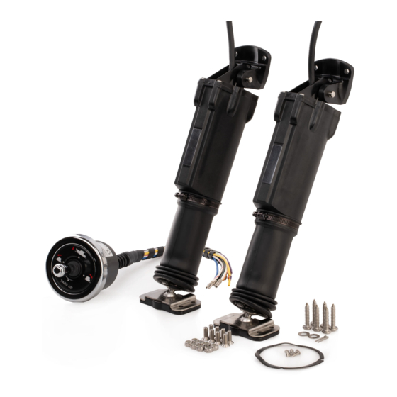
Installation and maintenance manual 2 TRANSPORT 2.1 Special warnings Since the weight of the product with its packaging is lower than 20 Kg (44 lbs), it can be handled manually. WARNING The staff in charge of handling the load must work with protective gloves and safety shoes. 2.2 Packaging Before using the system, check there is no damage due to transport or storage conditions. - Page 10 Installation and maintenance manual TAB PACKAGING Two tabs with the bag containing fixing screws Ref. Component Qty. Fixing screw bag Self-tapping screws ST6.3x32 NOTICE NOTICE For a correct installation, use all the screws provided in the packaging (7 for tabs 9"x9" and 12"x9", 8 for tabs 12"x12", 11 for tabs 12"x18").
-
Page 11: Necessary Tools
Installation and maintenance manual 3 INSTALLATION 3.1 Necessary tools Hammer Drill Pliers Tape measure Drill bits Open end Ø4,5mm (0.18") wrench Ø10mm (0.394") 10mm (0.39") Phillips Hole saw Ø70mm Ruler Sealant 3M 5200 Cutter screwdriver (2.75") 3.2 Tab installation Find the tab installation point as shown in the picture. WARNING Make sure the upper fixing bracket (A) of the actuator is not near other devices in the inner part of the transom obstructing the passage of the power cable. - Page 12 Installation and maintenance manual NOTICE In order to ensure a correct installation of the tabs, use the bigger holes (indicated by in the picture) Hinge for tab 9"x 9" and 12"x 9" on the hinge plate. NOTICE Hinge for tab 12"x 12" The smaller holes (indicated by in the picture ) are used for an installation replacing other systems.
- Page 13 Installation and maintenance manual Insert the upper bracket (G1) on actuator (A1) using only the pin (G2) but not the split pin (G3), WITHOUT inserting the cable through the bracket in order to mark its perimeter. CAUTION The bracket on the tab side allows an articulation of 7°...
- Page 14 Installation and maintenance manual 9 Make three Ø 5.5 mm (0.22") holes deep at least 25 mm (0.98") to fix bracket (G1) and Ø 10mm (0.39") (through) central hole to allow the passage of the power cable. 10 Insert the upper bracket (G1) on the actuator (A1) by using the pin (G2), the washer (G4) and the split pin (G3) supplied, by paying attention to pass...
-
Page 15: Joystick Installation
Installation and maintenance manual 3.3 Joystick installation 3.3 .1 Joystick positioning Position the control panel so that it does not hinder other controls or that it is not hindered by them. Refer to the overall dimensions indicated in paragraph 1.4 to make sure the joystick panel can be installed in the chosen position. -
Page 16: General Notes
Installation and maintenance manual 4 WIRINGS 4.1 General notes WARNING UFLEX is not to be held responsible for possible damages or malfunctions deriving from operation not workmanlike performed. The extension power cables supplied by UFLEX are high-quality, saltiness- and oil-resistant cables. In case an extension power cable is not long enough, replace it with a longer one. -
Page 17: Wiring Diagrams
Installation and maintenance manual 4.3 Wiring diagrams The following picture shows the product wiring diagram. J O Y S T I C K FI R ST S T AT I ON 15A MAGNETO-THERMAL SWITCH WHICH CAN BE MANUALLY RESET (NOT SUPPLIED) 1 (see par. -
Page 18: Actuator Connection
Installation and maintenance manual 4.3.1 Actuator connection 15A MAGNETO-THERMAL SWITCH WHICH CAN BE MANUALLY RESET (NOT SUPPLIED) +12V (POWER POSITIVE WIRE) RED - AWG 14 BLACK - AWG 14 GROUND BAR PORT ACTUATOR BLACK/RED - AWG 16 BLACK WHITE WHITE/RED - AWG 16 BLACK/GREEN - AWG BLACK WHITE/GREEN - AWG 16... -
Page 19: Auto Line-Up
Installation and maintenance manual 4.3.2 Auto line-up When running at idle or when the engine turns off, the auto line-up function allows putting the tabs in rest position automatically. The auto line-up function can be enabled by means of the panel key or the neutral safety switch of the control unit. - Page 20 Installation and maintenance manual Neutral safety switch: Single engine 15A MAGNETO-THERMAL SWITCH WHICH CAN BE MANUALLY RESET (NOT SUPPLIED) RED - AWG 14 ORANGE- AWG 18 +12V (POWER POSITIVE WIRE) BLACK/ORANGE - AWG 18 NEUTRAL SAFETY SWITCH WHITE/ORANGE - AWG 18 THE FOLLOWING WIRING KIT CAN BE USED Single engine BLACK/ORANGE - AWG 18...
- Page 21 Installation and maintenance manual 4.3.3 Connection of the second Joystick control station JOYSTICK FIRST STATION REFER TO THE CONNECTIONS SHOWN IN PARAGRAPHS 4.3.1 AND 4.3.2 RED - AWG 14 BLACK - AWG 14 JOYSTICK SECOND STATION (OPTIONAL) BLACK/RED - AWG 16 WHITE/RED - AWG 16 BLACK/GREEN - AWG 16 WHITE/GREEN - AWG 16...
-
Page 22: Use
Installation and maintenance manual 5 TRIM TAB USE This section aims at describing the supplied appliance explaining the system operation so that it can be properly used. Please, read the manual carefully before using the UFLEX Trim Tab system. This appliance is very easy to use, even for people who are not familiar with Trim Tab control systems and it allows improving sailing performances;... - Page 23 Installation and maintenance manual CHANGE WITH THE CHANGE TAB MOVEMENT JOYSTICK PLANING The electronic system can automatically enable an important function named "Auto line-up" which allows aligning the tabs at rest, without using the joystick. As explained in the wiring chapter, two different kinds of installation are available: engine key control or neutral safety switch control.
-
Page 24: Safety Rules During Use
Installation and maintenance manual IDLE POSITION OF THE SHIFT ON THE CONTROL BOX 5.2 Safety rules during use OBSERVE STRICTLY the following safety rules: UFLEX declines all responsibility in case the user does not follow these rules and it is not responsible for negligence during the use of the system. -
Page 25: Ordinary Maintenance
Installation and maintenance manual 6 MAINTENANCE 6.1 Ordinary maintenance A proper maintenance is an important factor for a longer duration of the trim tabs in optimum working conditions and it ensures safety from a functional point of view, Only skilled and properly trained staff should carry out maintenance operations. -
Page 26: Dismantling
Installation and maintenance manual 7 DISMANTLING 7.1 Dismantling When for any reason the system is put out of service, it is necessary to follow some rules in order to respect the environment. Sheaths, pipelines, plastic or non-metallic components must be disassembled and disposed of separately. page 26 of 83 - ELECTROMECHANICAL TRIM TABS... - Page 27 Installation and maintenance manual Joystick- Drilling template PRUA POPPA STERN Full size scale 50 mm (1.96") page 27 of 83 ELECTROMECHANICAL TRIM TABS...
- Page 28 Installation and maintenance manual NOTES page 28 of 83 - ELECTROMECHANICAL TRIM TABS...
- Page 29 Manuale d'uso e installazione CORRETTORI D'ASSETTO ELETTROMECCANICI PARTNER (Dr./Dis./Des. n° 31858/a 16/02/2017) ULTRAFLEX GROUP...
- Page 30 Gentile Cliente, I correttori d' assetto UFLEX sono prodotti da ULTRAFLEX società del GRUPPO ULTRAFLEX. Il GRUPPO ULTRAFLEX è da anni un punto di riferimento nella costruzione di accessori per la nautica da diporto e professionale. Da sempre la nostra produzione é sinonimo di grande affidabilità e sicurezza. Tutta la produzione ULTRAFLEX é...
- Page 31 Manuale d'uso e installazione INDICE GENERALE USO DEL MANUALE E SIMBOLOGIA IMPIEGATA....................32 LETTERA INFORMATIVA............................33 GARANZIA.....................................33 SEZIONE 1 - DESCRIZIONE DEL PRODOTTO DESCRIZIONE DEI CORRETTORI D'ASSETTO..................34 PRINCIPIO DI FUNZIONAMENTO......................34 DIMENSIONI ATTUATORE........................35 DIMENSIONI JOYSTICK..........................35 1.4.1 JOYSTICK LOW PROFILE......................35 1.4.2 JOYSTICK STANDARD..........................36 CARATTERISTICHE TECNICHE PALE......................36 SEZIONE 2 - TRASPORTO AVVERTENZE GENERALI...........................37 CONTENUTO DEGLI IMBALLI........................37...
-
Page 32: Uso Del Manuale E Simbologia Impiegata
Manuale d'uso e installazione USO DEL MANUALE E SIMBOLOGIA IMPIEGATA Il MANUALE DI INSTALLAZIONE E MANUTENZIONE è il documento che accompagna il prodotto dal momento della sua vendita fino alla sua sostituzione e smaltimento. Risulta cioè essere parte integrante del prodotto. E’... -
Page 33: Lettera Informativa
UFLEX sono utilizzati con unità di comando UFLEX. Per informazioni dettagliate si prega di contattare il nostro Servizio Assistenza. I correttori d'assetto UFLEX, prodotti da ULTRAFLEX sono marcati come richiesto dalla direttiva 2013/53/EU. Vi ricordiamo che sulle imbarcazioni marcate CE è obbligatorio installare connettori marcati CE. -
Page 34: Descrizione Dei Correttori D'assetto
Manuale d'uso e installazione 1 DESCRIZIONE DEL PRODOTTO 1.1 Descrizione dei correttori d'assetto L'uso delle pale permette all'imbarcazione di mantene- re un assetto adeguato alle varie condizioni di naviga- zione ottimizzandone le prestazioni. In caso di necessità (Fig.1), l'azionamento delle pale corregge e riequilibra l'assetto dell'imbarcazione (Fig. -
Page 35: Dimensioni Attuatore
Manuale d'uso e installazione 1.3 Dimensioni attuatore 273 mm 307 mm (10.75") (12.09") 330 mm 364 mm (13") (14.33") 1.4 Dimensioni joystick 1.4.1 Joystick low profile 72,5 mm (2.85") pag. 35 di 83 CORRETTORI D'ASSETTO ELETTROMECCANICI... -
Page 36: Joystick Standard
Manuale d'uso e installazione 1.4.2 Joystick standard Ø 92 mm (3.62") Ø 69,69 mm (2.76") 1.5 Caratteristiche tecniche pale MONTAGGIO "STANDARD" 12" 12" 12" A inches/mm 9" (229mm) (305mm) (305mm) (305mm) 12" 18" B inches/mm 9" (229mm) 9" (229mm) (305mm) (457mm) pag. -
Page 37: Avvertenze Generali
Manuale d'uso e installazione 2 TRASPORTO 2.1 Avvertenze generali Dato che il peso del prodotto compreso l'imballo è inferiore a 20 Kg (44 lbs), la sua movimentazione può essere effettuata manualmente. AVVERTENZA Il personale addetto alla manipolazione del carico deve operare con guanti protettivi e scarpe anti infortunistiche. - Page 38 Manuale d'uso e installazione IMBALLO PALE Due pale con il sacchetto delle viti di fissaggio Rif. Componente Pala Sacchetto viti di fissaggio Viti autofilettanti ST6.3x32 NOTA NOTA Per una corretta installazione è necessario usare tutte le viti fornite nell'imballo (7 per le pale 9"x9" e 12"x9", 8 per le pale 12"x12", 11 per le pale 12"x18").
-
Page 39: Utensili Necessari
Manuale d'uso e installazione 3 INSTALLAZIONE 3.1 Utensili necessari Martelletto Trapano Tagliafili Metro a nastro Punte di Chiave fissa perforazione 10mm (0.39") Ø4,5mm (0.18") Ø10mm (0.394") Cacciavite a Fresa a tazza Riga Sigillante 3M Taglierino croce Ø70mm (2.75") 5200 3.2 Installazione delle pale Individuare il punto di installazione delle pale come indicato in figura. - Page 40 Manuale d'uso e installazione NOTA Per garantire la corretta installazione delle pale utilizzare i fori di fissaggio di diametro maggiore Cerniera per pala 9"x 9" e 12"x 9" (indicati in figura da ) posti sulla piastra della cerniera. NOTA Cerniera per pala 12"x 12" I fori di diametro minore (indicati in figura da vengono utilizzati per una installazione in sostituzione ad altri sistemi.
- Page 41 Manuale d'uso e installazione Per poterne segnare il perimetro inserire la staffa superiore (G1) sull’attuatore (A1) utilizzando il solo perno (G2) ma non la coppiglia (G3), avendo l’accorgimento di NON inserire il cavo attraverso la staffa. ATTENZIONE La staffa lato pala consente uno snodo di 7°...
- Page 42 Manuale d'uso e installazione 9 Effettuare tre fori Ø 5.5 mm (0.22") di profondità di almeno 25 mm (0.98") per il fissaggio della staffa (G1) e il foro centrale Ø 10mm (0.39") (passante) per il passaggio del cavo di alimentazione Inserire la staffa superiore (G1 ) sull'attuatore (A1) utilizzando il perno (G2), la rondella (G4) e la coppiglia (G3) in...
-
Page 43: Installazione Del Joystick
Manuale d'uso e installazione 3.3 Installazione del joystick 3.3 .1 Posizionamento del joystick Posizionare il pannello di controllo in modo che lo stesso non ostacoli altri comandi o non venga ostacolato da questi ultimi. Riferirsi alle quote d'ingombro indicate al paragrafo 1.4 per verificare che il pannello del joystick possa essere effettivamente installato nella posizione prescelta. -
Page 44: Note Generali
Manuale d'uso e installazione 4 CABLAGGI 4.1 Note generali AVVERTENZA UFLEX non è responsabile di eventuali danni o malfunzionamenti derivanti da operazioni svolte non a regola d'arte. I cavi di prolunga alimentazione forniti da UFLEX sono cavi di alta qualità resistenti al salino e agli olii. Qualora un cavo di prolunga alimentazione risulti di lunghezza insufficiente è... -
Page 45: Schemi Di Cablaggio
Manuale d'uso e installazione 4.3 Schemi di cablaggio Di seguito è fornito lo schema di cablaggio del prodotto. J O Y S T I C K P RI MA S T AZI ON E INTERRUTTORE MAGNETO-TERMICO DA 15A MANUALMENTE RIPRISTINABILE 1 (v. -
Page 46: Collegamento Attuatori
Manuale d'uso e installazione 4.3.1 Collegamento attuatori INTERRUTTORE MAGNETO-TERMICO DA 15A MANUALMENTE RIPRISTINABILE (NON FORNITO) +12V (POSITIVO DI ALIMENTAZIONE) ROSSO - AWG 14 NERO - AWG 14 BARRA EQUIPOTENZIALE ATTUATORE SINISTRO NERO/ROSSO - AWG 16 NERO BIANCO BIANCO/ROSSO - AWG 16 NERO/VERDE - AWG 16 NERO BIANCO/VERDE - AWG 16... -
Page 47: Auto Line-Up
Manuale d'uso e installazione 4.3.2 Auto line-up In condizione di marcia in folle o di spegnimento del motore, la funzione di autoline-up permette di riportare automaticamente le pale in una condizione di riposo. Per usufruire delle funzionalità di autoline-up si può usare la chiave di quadro oppure l’interruttore di neutral safety switch dell’unita di comando. - Page 48 Manuale d'uso e installazione Neutral safety switch: Monomotore INTERRUTTORE MAGNETO-TERMICO DA 15A MANUALMENTE RIPRISTINABILE (NON FORNITO) ROSSO - AWG 14 ARANCIONE - AWG 18 +12V (POSITIVO DI ALIMENTAZIONE) NERO/ARANCIONE - AWG 18 BIANCO/ARANCIONE - AWG 18 NEUTRAL SAFETY SWITCH E’...
- Page 49 Manuale d'uso e installazione 4.3.3 Collegamento seconda stazione comando Easy-Joy JOYSTICK PRIMA STAZIONE RIFERIRSI ALLE CONNESSIONI MOSTRATE AI PARAGRAFI 4.3.1 E 4.3.2 ROSSO - AWG 14 NERO - AWG 14 JOYSTICK SECONDA STAZIONE (OPZIONALE) NERO/ROSSO - AWG 16 BIANCO/ROSSO - AWG 16 NERO/VERDE - AWG 16 BIANCO/VERDE - AWG 16 ARANCIONE - AWG 18...
-
Page 50: Utilizzo
Manuale d'uso e installazione 5 USO DEI CORRETTORI D'ASSETTO Questa sezione ha lo scopo di descrivere l'apparecchiatura fornita e di illustrare il funzionamento del sistema per consentirne un corretto utilizzo. Si raccomanda di leggere con molta attenzione il manuale UFLEX prima di utilizzare il sistema Trim Tab L'estrema semplicità... - Page 51 Manuale d'uso e installazione AZIONE CORRETTIVA AZIONE CORRETTIVA MOVIMENTO DELLE PALE CON IL JOYSTICK PLANATA Il sistema elettronico può attivare automaticamente un'importante funzione, detta di "Auto line-up", la quale consente di riallineare le pale in condizioni di riposo, senza utilizzare il joystick. Come illustrato nel capitolo del cablaggi, è...
-
Page 52: Norme Di Sicurezza Durante L'uso
Manuale d'uso e installazione 5.2 Norme di sicurezza durante l'uso RISPETTATE TASSATIVAMENTE le precauzioni ed i criteri di sicurezza indicati qui di seguito. UFLEX declina ogni responsabilità nel caso in cui l'utilizzatore non li osservi, così come non è responsabile per qualsiasi tipo di negligenza che venga commessa durante l'utilizzo del dispositivo. -
Page 53: Manutenzione Ordinaria
Manuale d'uso e installazione 6 MANUTENZIONE 6.1 Manutenzione ordinaria Un’adeguata manutenzione costituisce un fattore determinante per una maggiore durata dei correttori d'assetto in condizioni di funzionamento e di rendimento ottimali e garantisce nel tempo la sicurezza sotto il profilo funzionale. Si raccomanda di far eseguire le operazioni di manutenzione a personale addestrato ed autorizzato. -
Page 54: Smantellamento
Manuale d'uso e installazione 7 SMANTELLAMENTO 7.1 Smantellamento Qualora si intenda, per qualsiasi motivo, mettere fuori servizio i correttori d'assetto, è necessario osservare alcune regole fondamentali atte a salvaguardare l’ambiente. Guaine, condotti flessibili, componenti di materiale plastico o comunque non metallico, dovranno essere smontati e smaltiti separatamente. - Page 55 Manuale d'uso e installazione Joystick - Dima di foratura PRUA POPPA STERN Scala 1:1 50 mm (1.96") pag. 55 di 83 CORRETTORI D'ASSETTO ELETTROMECCANICI...
- Page 56 Manuale d'uso e installazione NOTE pag. 56 di 83 - CORRETTORI D'ASSETTO ELETTROMECCANICI...
- Page 57 Manuel d'installation et d'entretien FLAPS - STABILISATEURS ELECTROMECANIQUES POUR BATEAUX PARTNER (Dr./Dis./Des. n° 31858/a 16/02/2017) ULTRAFLEX GROUP...
- Page 58 Cher Client, Les stabilisateurs UFLEX sont fabriqués par la ULTRAFLEX société du GROUPE ULTRAFLEX. Le GROUPE ULTRAFLEX est depuis plusieurs années un point de réfèrence dans la construction d'accessoires dans le domaine de la navigation de plaisance et professionnelle. Notre production est depuis toujours une garantie de grande fiabilité et sécurité. Tous les produits ULTRAFLEX sont conçus et fabriqués pour assurer toujours les performances les meilleures.
- Page 59 Manuel d'installation et d'entretien INDEX GENERAL EMPLOI DU MANUEL ET SYMBOLES UTILISES....................60 LETTRE D'INFORMATION............................61 GARANTIE................................61 SECTION 1 - DESCRIPTION DU PRODUIT DESCRIPTION FLAPS..................62 PRINCIPE DE FONCTIONNEMENT......................62 DIMENSIONS DU VERIN........................63 DIMENSIONS JOYSTICK......................63 1.4.1 JOYSTICK LOW PROFILE......................63 1.4.2 JOYSTICK STANDARD......................64 CARACTERISTIQUES TECHNIQUES DES PELLES................64 SECTION 2 - TRANSPORT AVERTISSEMENTS GENERAUX........................65 CONTENU EMBALLAGE........................65...
-
Page 60: Emploi Du Manuel Et Symboles Utilises
Manuel d'installation et d'entretien EMPLOI DU MANUEL ET SYMBOLES UTILISES Le MANUEL D'INSTALLATION ET D'ENTRETIEN est le document qui accompagne le produit de sa vente jusqu'à son remplacement et son démontage. C'est donc une partie fondamentale du produit. Il faut lire le manuel avant TOUTE ACTIVITE concernant le produit y compris sa manutention et son déchargement du moyen de transport. -
Page 61: Lettre D'information
Les descriptions et les illustrations contenues dans ce manuel sont seulement à titre indicatif. La garantie opère exclusivement si les stabilisateurs UFLEX sont utilisés avec des unités de commande UFLEX. Pour toute information détaillée contacter notre Service d'Assistance. Les stabilisateurs UFLEX, produits par ULTRAFLEX sont pourvus de la marque en conformité avec la directive 2013/53/UE. -
Page 62: Description Des Flaps
Manuel d'installation et d'entretien 1 DESCRIPTION DU PRODUIT 1.1 Description des flaps L'emploi des pelles permet au bateau de maintenir une assiette adéquate aux différentes conditions de navigation en optimisant les performances. Si nécessaire (Fig.1), l'actionnement des pelles corrige et rééquilibre l'assiette du bateau (Fig. -
Page 63: Dimensions Du Verin
Manuel d'installation et d'entretien 1.3 Dimensions du vérin 273 mm 307 mm (10.75") (12.09") 330 mm 364 mm (13") (14.33") 1.4 Dimensions joystick 1.4.1 Joystick low profile 72,5 mm (2.85") page 63 de 83 STABILISATEURS... -
Page 64: Joystick Standard
Manuel d'installation et d'entretien 1.4.2 Joystick standard Ø 92 mm (3.62") Ø 69,69 mm (2.76") 1.5 Caractéristiques techniques des pelles ASSEMBLAGE "STANDARD" 12" 12" 12" A inches/mm 9" (229mm) (305mm) (305mm) (305mm) 12" 18" B inches/mm 9" (229mm) 9" (229mm) (305mm) (457mm) page 64... -
Page 65: Avertissements Generaux
Manuel d'installation et d'entretien 2 TRANSPORT 2.1 Avertissements généraux Le poids du produit avec l'emballage est inférieur à 20 Kg (44 lbs), donc sa manutention peut être effectuée manuellement. AVERTISSEMENT Le personnel préposé à la manipulation de la charge doit porter des gants de protection et des chaussures de sécurité. - Page 66 Manuel d'installation et d'entretien EMBALLAGE PELLES Deux pelles pourvues de sac des vis de fixation Réf. Composant Pelle compensateur Sac vis de fixation Vis autotaradeuses ST6.3x32 NOTE NOTE Pour une installation correcte il faut utiliser toutes les vis fournies dans l'emballage (7 pour les pelles 9"x9" et 12"x9", 8 pour les pelles 12"x12", 11 pour les pelles 12"x18").
-
Page 67: Outils Necessaires
Manuel d'installation et d'entretien 3 INSTALLATION 3.1 Outils nécessaires Marteau Perceuse Coupe-fil Mètre à ruban Pointes de Clé fixe perçage 10mm (0.39") Ø4,5mm (0.18") Ø10mm (0.394") Tournevis Fraise creuse Règle Colle pour Dispositif de cruciforme Ø70mm (2.75") sceller 3M 5200 coupe 3.2 Installation des pelles Déterminer le point d'installation des pelles comme indiqué... - Page 68 Manuel d'installation et d'entretien NOTE Pour installer correctement les pelles utiliser les trous de fixation de diamètre supérieur (indiqués Charnière pour pelle 9"x 9" e 12"x 9" dans la figure par ) placés sur la plaque de la charnière. NOTE Charnière pour pelle 12"x 12"...
- Page 69 Manuel d'installation et d'entretien Insérer l'étrier supérieur (G1) sur le vérin (A1) en utilisant seulement le pivot (G2) mais pas la goupille (G3), en faisant attention à NE PAS insérer le câble à travers l'étrier pour pouvoir marquer le périmètre. ATTENTION L'étrier côté...
- Page 70 Manuel d'installation et d'entretien 10 Effectuer trois trous Ø 5,5mm (0.22") profondeur d'au moins 25mm pour la fixation de l'étrier (A) et le trou central Ø 10mm (0.39") (débouchant) pour le passage du câble d'alimentation. 11 Insérer l'étrier supérieur (G1) sur le vérin (A1) en utilisant le pivot (G2), la rondelle (G4) et la goupille (G3) fournis, en faisant attention de faire...
-
Page 71: Installation Joystick
Manuel d'installation et d'entretien 3.3 Installation joystick 3.3 .1 Positionnement joystick Positionner le panneau de commande de façon qu'il n'empêche pas les autres commandes ou qu'il ne soit pas empêché par ces dernières. Consulter les dimensions d'encombrement indiquées au paragraphe 1.4 pour vérifier que le panneau Joystick puisse être effectivement installé... -
Page 72: Notes Generales
Manuel d'installation et d'entretien 4 CABLAGES 4.1 Notes générales AVERTISSEMENT UFLEX n'est pas responsable pour tout dommage ou mauvais fonctionnement dérivant des opérations non effectuées à règles d'art. Les câbles de rallonge alimentation fournis par la Société UFLEX sont des câbles de haute qualité résistants au milieu salin et aux huiles. -
Page 73: Schemas De Cablage
Manuel d'installation et d'entretien 4.3 Schémas de câblage Le câblage du produit est indiqué ci-dessous. J O Y S T I C K P RE MI ER P OS T E INTERRUPTEUR MAGNETOTHERMIQUE DE 15A QUI 1 (v. par. 4.3.1) PEUT ETRE RETABLI MANUELLEMENT (NON FOURNI) +12V (CABLE POSITIF D'ALIMENTATION) - Page 74 Manuel d'installation et d'entretien 4.3.1 Connexions vérins INTERRUPTEUR MAGNETOTHERMIQUE DE 15A QUI PEUT ETRE RETABLI MANUELLEMENT (NON FOURNI) +12V (CABLE POSITIF D'ALIMENTATION) ROUGE - AWG 14 NOIR - AWG 14 BARRE EQUIPOTENTIELLE VERIN GAUCHE NOIR/ROUGE - AWG 16 NOIR BLANC BLANC/ROUGE - AWG 16 NOIR/VERT - AWG 16 NOIR...
-
Page 75: Auto Line-Up
Manuel d'installation et d'entretien 4.3.2 Auto line-up La fonction de “auto line-up” permet de porter automatiquement les pelles dans une position de repos quand le moteur est arrêté ou la commande de changement de vitesse est au point mort (neutral). Pour bénéficier des fonctionnalités d'autoline-up on peut utiliser la clé... - Page 76 Manuel d'installation et d'entretien Neutral safety switch: Moteur unique INTERRUPTEUR MAGNETOTHERMIQUE DE 15A QUI PEUT ETRE RETABLI MANUELLEMENT (NON FOURNI) ROUGE - AWG 14 ORANGE- AWG 18 +12V (CABLE POSITIF D'ALIMENTATION) NOIR/ORANGE - AWG 18 BLANC/ORANGE - AWG 18 NEUTRAL SAFETY SWITCH IL EST POSSIBLE D'UTILISER LE KIT DE CABLAGE SUIVANT Moteur unique...
- Page 77 Manuel d'installation et d'entretien 4.3.3 Connexion du deuxième poste de la commande Joystick JOYSTICK PREMIER POSTE SE REFERER AUX CONNEXIONS INDIQUEES DANS LES PARAGRAPHES 4.3.1 ET 4.3.2 ROUGE - AWG 14 NOIR - AWG 14 JOYSTICK DEUXIEME POSTE (OPTIONNEL) NOIR/ROUGE - AWG 16 BLANC/ROUGE - AWG 16 NOIR/VERT - AWG 16 BLANC/VERT - AWG 16...
-
Page 78: Emploi
Manuel d'installation et d'entretien 5 EMPLOI DES FLAPS Cette section décrit l'appareillage fourni et illustre le fonctionnement du système pour permettre un emploi correct. On recommande de lire avec beaucoup d'attention le manuel avant d'utiliser le système Flaps UFLEX La simplicité extrême d'emploi permet un accroissement des performances de gouvernement même si on n'est pas familiarisé... - Page 79 Manuel d'installation et d'entretien CHANGEMENT AVEC CHANGEMENT DEPLACEMENT DES PELLES JOYSTICK PLANAGE Le système électronique peut activer automatiquement une fonction importante de "Auto line-up", laquelle permet de réaligner les pelles en conditions de repos, sans utiliser joystick. Comme indiqué dans le chapitre des câblages, il est possible d'avoir deux types différents d'installation: avec commande de la clé...
-
Page 80: Normes De Securite Pendant L'installation Et L'emploi
Manuel d'installation et d'entretien POSITION NEUTRE DE L'INVERSEUR SUR LA BOITE DE COMMANDE 5.2 Normes de sécurité pendant l'installation et l'emploi RESPECTER RIGOUREUSEMENT les précautions et les critères de sécurité indiqués ci-dessous. La Société UFLEX décline toute responsabilité au cas où l'usager ne les respecterait pas; elle n'est pas non plus responsable pour tout type de négligence commise pendant l'emploi du système. -
Page 81: Entretien Ordinaire
Manuel d'installation et d'entretien 6 ENTRETIEN 6.1 Entretien ordinaire Un entretien adéquat constitue un facteur déterminant pour une durée supérieure des stabilisateurs en conditions de fonctionnement et de rendement optimales et il assure dans le temps la sécurité sous le profil fonctionnel. -
Page 82: Demontage Et Ecoulement
Manuel d'installation et d'entretien 7 DEMONTAGE 7.1 Démontage et Ecoulement Si les flaps doivent être mis hors service pour quelques raisons que ce soit, les règles fondamentales suivantes doivent être observées pour la protection de l'environnement. aines, conduits flexibles, composants de matériel plastique ou non métalliques, devront être désassemblés et éliminés séparément. - Page 83 Manuel d'installation et d'entretien Joystick - Gabarit de perçage PROUE POUPE STERN Echelle 1:1 50 mm (1.96") page 83 de 83 STABILISATEURS...
- Page 84 Via Milite Ignoto,8A 16012 Busalla (GE)-Italy...