Miller RAD-400 Manuel D'utilisation
Masquer les pouces
Voir aussi pour RAD-400:
- Manuel de l'utilisateur (28 pages) ,
- Mode d'emploi (28 pages) ,
- Manuel du propriétaire (32 pages)

Manuels Connexes pour Miller RAD-400


Sommaire des Matières pour Miller RAD-400
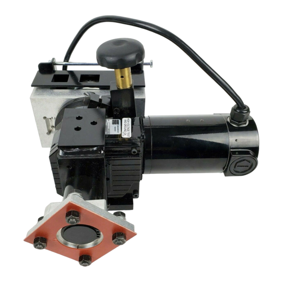
- Page 1 OM-1598 199 752 July 2000 Processes Submerged (SAW) Welding Description Heavy Duty Wire Feeder For Automated Welding Applications RAD-400 And RAD-780 Motor/Drive Assemblies Visit our website at www.MillerWelds.com...
- Page 2 – every power source from This Owner’s Manual is designed to help you get the most out of your Miller is backed by the most Miller products. Please take time to read the Safety precautions. They will hassle-free warranty in the business.
-
Page 3: Table Des Matières
TABLE OF CONTENTS SECTION 1 – SAFETY PRECAUTIONS - READ BEFORE USING ......1-1. -
Page 5: Section 1 - Safety Precautions - Read Before Using
SECTION 1 – SAFETY PRECAUTIONS - READ BEFORE USING som _nd_4/98 1-1. Symbol Usage Means Warning! Watch Out! There are possible hazards with this procedure! The possible hazards are shown in the adjoining symbols. This group of symbols means Warning! Watch Out! possible Y Marks a special safety message. - Page 6 ARC RAYS can burn eyes and skin. BUILDUP OF GAS can injure or kill. D Shut off shielding gas supply when not in use. Arc rays from the welding process produce intense D Always ventilate confined spaces or use visible and invisible (ultraviolet and infrared) rays that can burn eyes and skin.
-
Page 7: Additional Symbols For Installation, Operation, And Maintenance
1-3. Additional Symbols For Installation, Operation, And Maintenance FIRE OR EXPLOSION hazard. MOVING PARTS can cause injury. D Do not install or place unit on, over, or near D Keep away from moving parts such as fans. combustible surfaces. D Keep all doors, panels, covers, and guards D Do not install unit near flammables. -
Page 8: Emf Information
1-5. EMF Information Considerations About Welding And The Effects Of Low Frequency 1. Keep cables close together by twisting or taping them. Electric And Magnetic Fields 2. Arrange cables to one side and away from the operator. Welding current, as it flows through welding cables, will cause electro- magnetic fields. -
Page 9: Section 1 - Consignes De Securite - Lire Avant Utilisation
SECTION 1 – CONSIGNES DE SECURITE – LIRE AVANT UTILISATION som _nd_fre 4/98 1-1. Signification des symboles Signifie Mise en garde ! Soyez vigilant ! Cette procédure présente des risques de danger ! Ceux-ci sont identifiés par des symboles adjacents aux directives. Ce groupe de symboles signifie Mise en garde ! Soyez vigilant ! Il y a des Y Identifie un message de sécurité... - Page 10 LES RAYONS DE L’ARC peuvent pro- LES ACCUMULATIONS DE GAZ ris- voquer des brûlures dans les yeux et quent de provoquer des blessures ou sur la peau. même la mort. Le rayonnement de l’arc du procédé de soudage D Fermer l’alimentation du gaz protecteur en cas de génère des rayons visibles et invisibles intenses non utilisation.
-
Page 11: Dangers Supplémentaires En Relation Avec L'installation, Le Fonctionnement Et La Maintenance
1-3. Dangers supplémentaires en relation avec l’installation, le fonctionnement et la maintenance Risque D’INCENDIE OU DES ORGANES MOBILES peuvent D’EXPLOSION. provoquer des blessures. D Ne pas placer l’appareil sur, au-dessus ou à proxi- D Rester à l’écart des organes mobiles comme le mité... -
Page 12: Principales Normes De Sécurité
1-4. Principales normes de sécurité Safety in Welding and Cutting, norme ANSI Z49.1, de l’American Wel- Safe Handling of Compressed Gases in Cylinders, CGA Pamphlet P-1, ding Society, 550 N.W. Lejeune Rd, Miami FL 33126 de la Compressed Gas Association, 1235 Jefferson Davis Highway, Suite 501, Arlington, VA 22202. -
Page 13: Section 2 - Installation
SECTION 2 – INSTALLATION 2-1. Specifications Wire Feed Speed Wire Feed Speed Wire Diameter Wire Diameter Type Of Input Type Of Input Input Power Input Power Model Rating Weight Range Range Power Cord 0 To 400 ipm 3/32 To 7/32 in 1/4 HP, 33 lb RAD–400... -
Page 14: Overall Dimensions And Mounting Hole Layout
2-3. Overall Dimensions And Mounting Hole Layout Inches Millimeters Inches Millimeters 2-1/2 4-5/8 10-1/2 4-1/4 13/32 Dia. 10.3 Dia. 8 Holes 8 Holes 3/8-16 Tapped 8 Holes 802 594-B 2-4. Typical Equipment Location Side View Front View 802 605 Welding Power Source Weld Control Wire Drive Assembly Side Beam... -
Page 15: Installing Wire Guide And Drive Roll
2-5. Installing Wire Guide And Drive Roll When changing wire size or type, check drive roll size (see Table 5-1). Wire Pressure Adjustment Screw Loosen screw to decrease tension on spring. Drive Roll Nut Drive Roll Carrier Turn nut one click to line up lobes with lobes on drive roll carrier. -
Page 16: Plug Connections
2-6. Plug Connections Weld Control Motor Control Cord (Not Supplied) Motor/Drive Assembly To make connections, align key- way, insert plug, and tighten threaded collar. 802 594-B / 802 269 / 802 530 OM-1598 Page 12... -
Page 17: Threading And Feeding Welding Wire
2-7. Threading And Feeding Welding Wire Hold wire tightly to keep it from unraveling. POWER Tools Needed: Weld Control Welding Power Source 6 in (150 mm) Pull and hold wire; cut off end. Set switches. WIRE ADVANCE Cut off wire at a diagonal. Push wire thru guide up to drive rolls;... -
Page 18: Manually Changing Feed Plate Angle
2-9. Manually Changing Feed Plate Angle Feed Plate Screw Loosen screw. Hub Clamp Screw Tighten screw. Adjusting Knob Turn adjusting knob to change torch angle. The feed plate maximum tilt angle is about 15 degrees from center in both directions. Tools Needed: 1/4 in 15°... -
Page 19: Location Of Torch For Tandem Arc Applications
2-10. Location Of Torch For Tandem Arc Applications Follow instructions below to change torch to right of center or left of center. Assembly As Shipped Tools Needed: 1/4, 3/16 in 3/8 in Torch Left Of Center Torch Right Of Center 802 594-B / ST-802 599 Feed Plate Hub Clamp Assembly... -
Page 20: Section 3 - Maintenance And Troubleshooting
SECTION 3 – MAINTENANCE AND TROUBLESHOOTING 3-1. Routine Maintenance Y Disconnect power before maintaining. 3 Months Clean Repair Or Replace Replace Unreadable Tighten Cracked Labels Weld Weld Terminals Cable Replace Cord Cracked Hose Cable Parts 6 Months Blow Out Or Clean Vacuum Inside. -
Page 21: Troubleshooting
3-3. Troubleshooting Trouble Remedy Electrode wire feeding stops or feeds er- Readjust hub tension and drive roll pressure. ratically during welding. Change to correct size drive roll. Clean or replace dirty or worn drive roll. Check and replace incorrect size or worn wire guides. Replace contact tip or liner. -
Page 22: Section 5 - Parts List
SECTION 5 – PARTS LIST Hardware is common and not available unless listed. See Table 5-1 For Replacement Drive Rolls 802 595-B Figure 5-1. Wire Drive Assembly OM-1598 Page 18... - Page 23 Item Dia. Part Mkgs. Description Quantity RAD 400 - 194 764 Figure 5-1. Wire Drive Assembly RAD 780 - 194 763 ... . . 198498 ..Bracket, Mounting Flux Hopper .
- Page 24 OM-1598 Page 20...
- Page 25 OM-1598 Page 21...
- Page 26 OM-1598 Page 22...
- Page 27 Effective January 1, 2000 (Equipment with a serial number preface of “LA” or newer) This limited warranty supersedes all previous Miller warranties and is exclusive with no other Warranty Questions? guarantees or warranties expressed or implied. Call LIMITED WARRANTY – Subject to the terms and conditions APT, ZIPCUT &...
-
Page 28: For Service
Distributor Address City State For Service Call 1-800-4-A-Miller or see our website at www.MillerWelds.com to locate a DISTRIBUTOR or SERVICE AGENCY near you. Always provide Model Name and Serial/Style Number. Contact your Distributor for: Welding Supplies and Consumables Options and Accessories...