Table des Matières
Publicité
Liens rapides
Publicité
Table des Matières

Manuels Connexes pour Miller S-74 Boom w/Drive


Sommaire des Matières pour Miller S-74 Boom w/Drive
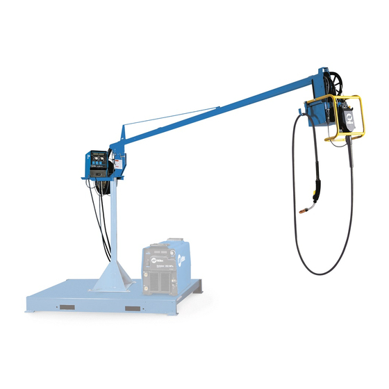
- Page 1 2018−02 Processes MIG (GMAW) Welding Flux Cored (FCAW) Welding (Gas-and Self-Shielding) Submerged (SAW) Welding Description Boom w/drive S-74 Boom w/Drive 8 ft, 12 ft, and 16 ft For product information, File: MIG (GMAW) Owner’s Manual translations, and more, visit www.MillerWelds.com...
- Page 2 We know you don’t have time to do it any other way. That’s why when Niels Miller first started building arc welders in 1929, he made sure his products offered long-lasting value and superior quality.
-
Page 3: Table Des Matières
TABLE OF CONTENTS SECTION 1 − SAFETY PRECAUTIONS - READ BEFORE USING ........1-1. -
Page 5: Section 1 − Safety Precautions - Read Before Using
SECTION 1 − SAFETY PRECAUTIONS - READ BEFORE USING som 2018−01 Protect yourself and others from injury — read, follow, and save these important safety precautions and operating instructions. 1-1. Symbol Usage DANGER! − Indicates a hazardous situation which, if Indicates special instructions. - Page 6 D Do not cut or weld on tire rims or wheels. Tires can explode if heat- FUMES AND GASES can be hazardous. ed. Repaired rims and wheels can fail. See OSHA 29 CFR 1910.177 listed in Safety Standards. D Do not weld on containers that have held combustibles, or on Welding produces fumes and gases.
-
Page 7: Additional Symbols For Installation, Operation, And Maintenance
D Never weld on a pressurized cylinder − explosion will result. CYLINDERS can explode if damaged. D Use only correct compressed gas cylinders, regulators, hoses, and fittings designed for the specific application; maintain them Compressed gas cylinders contain gas under high and associated parts in good condition. -
Page 8: California Proposition 65 Warnings
H.F. RADIATION can cause interference. ARC WELDING can cause interference. D High-frequency (H.F.) can interfere with radio D Electromagnetic energy can interfere with navigation, safety services, computers, and sensitive electronic equipment such as communications equipment. computers and computer-driven equipment such as robots. D Have only qualified persons familiar with electronic equipment D Be sure all equipment in the welding area is electromagnetically perform this installation. -
Page 9: Section 2 − Consignes De Sécurité − Lire Avant Utilisation
SECTION 2 − CONSIGNES DE SÉCURITÉ − LIRE AVANT UTILISATION som_2018−01_fre Pour écarter les risques de blessure pour vous−même et pour autrui — lire, appliquer et ranger en lieu sûr ces consignes relatives aux précautions de sécurité et au mode opératoire. 2-1. - Page 10 D Déplacer toutes les substances inflammables à une distance de LES PIÈCES CHAUDES peuvent 10,7 m de l’arc de soudage. En cas d’impossibilité les recouvrir provoquer des brûlures. soigneusement avec des protections homologués. D Ne pas toucher à mains nues les parties chaudes. D Ne pas souder dans un endroit là...
-
Page 11: Dangers Supplémentaires En Relation Avec L'installation, Le Fonctionnement Et La Maintenance
D Protéger les bouteilles de gaz comprimé d’une chaleur excessive, Les CHAMPS ÉLECTROMAGNÉTIQUES (CEM) des chocs mécaniques, des dommages physiques, du laitier, des peuvent affecter les implants médicaux. flammes ouvertes, des étincelles et des arcs. D Placer les bouteilles debout en les fixant dans un support station- D Les porteurs de stimulateurs cardiaques et naire ou dans un porte-bouteilles pour les empêcher de tomber ou autres implants médicaux doivent rester à... -
Page 12: Proposition Californienne 65 Avertissements
D Effectuer régulièrement le contrôle et l’entretien de l’installation. LIRE LES INSTRUCTIONS. D Maintenir soigneusement fermés les portes et les panneaux des sources de haute fréquence, maintenir les éclateurs à une distan- D Lire et appliquer les instructions sur les ce correcte et utiliser une terre et un blindage pour réduire les étiquettes et le Mode d’emploi avant l’instal- interférences éventuelles. -
Page 13: Section 3 − Specifications
SECTION 3 − SPECIFICATIONS 3-1. Serial Number And Stock Number Label Location The serial number and rating information for this product is located on the rear panel. For future reference, write serial number in space provided on back cover of this manual. 3-2. -
Page 14: Section 4 − Installation
SECTION 4 − INSTALLATION 4-1. Installing Swivel Into Pipe Post Swingpak Base or CBC Cart Pipe Post With Base Steel Bolt Secure as shown using as a mini- mum 1/2 in. diameter SAE grade 5 steel bolts. Swivel Assembly Insert into pipe post. Lubricate swivel. -
Page 15: Installing Boom And Reel Support
4-3. Installing Boom And Reel Support Swivel Plates Yoke Remove hardware from swivel plates and yoke. Boom Set boom into swivel as shown. Yoke Pin Install pin through yoke. Install cot- ter pin and spread ends. Bolt Install bolt, tighten hardware, and back bolt off one half turn. -
Page 16: Equipment Connection Diagram
4-5. Equipment Connection Diagram Welding Power Source Remote 14 Connection Positive (+) Weld Output Cable Negative (−) Weld Output Cable Workpiece Weld Control (Ref) Boom Trigger Connection 10 Swivel 11 Pipe Post And Base 12 Gas Hose 13 Gas Supply And Regulator (Customer Supplied) Shielding gas pressure not to exceed 100 psi (689 kPa). -
Page 17: Control Box Connections
4-6. Control Box Connections Interconnecting Cable Receptacle Interconnecting Cable 14-Pin Receptacle Ref. 805415-E 4-7. 14-Pin Plug Information Pin* Pin Information 24 volts AC with respect to socket G. Contact closure to A completes 24 volts AC contactor control circuit. Circuit common for 24 volts AC circuit. +10 volts DC output to remote control with respect to socket D. -
Page 18: Removing Safety Collar And Adjusting Boom
4-8. Removing Safety Collar And Adjusting Boom Locking Knob Tighten knob to prevent boom movement. Loosen knob to allow boom movement. Change knob po- sition to limit upward movement. Pull boom down slightly and remove safety collar. Boom should balance in any position from horizontal to 60 degrees above horizontal. -
Page 19: Installing Welding Gun
4-10. Installing Welding Gun Gun Locking Tab Power Clamp Knob Gun Connection End Power Pin Groove Installing gun with Accu-Mate connection Loosen power clamp knob to allow power pin of gun to clear the gun locking tab. Push power pin into power clamp as far as possible to align the groove in the power pin of the gun with the gun locking tab. -
Page 20: Installing And Threading Welding Wire
4-11. Installing And Threading Welding Wire Tools Needed: 15/16, 3/8 in. 3/16, 5/64 in. Install wire spool. Ad- just tension nut so wire is taut when wire feed stops. Pressure Adjust Pressure Indicator Scale Install wire guide. Pressure Adjust Drive Rolls Install drive rolls. -
Page 21: Section 5 − Maintenance
SECTION 5 − MAINTENANCE 5-1. Routine Maintenance Disconnect power before maintaining. 3 Months Clean and Repair or tighten Replace replace weld unreadable cracked terminals. labels. weld cable. Replace Check Check gas Check gun cracked 14-pin cord. hose and cable. parts. fittings. -
Page 22: Section 6 − Parts List
SECTION 6 − PARTS LIST Hardware is common and not available unless listed. 805419-E Figure 6-1. Main Assembly OM-252045 Page 18... - Page 23 Quantity Model Item Dia. Part Mkgs. Description Figure 6-1. Main Assembly ....201319 Cable, Interconnecting (Includes) ..... .
- Page 24 Hardware is common and not available unless listed. 142601-K Figure 6-2. Boom Assembly OM-252045 Page 20...
- Page 25 Quantity Model Item Part Description Figure 6-2. Boom Assembly (Figure 6-1 Item 11) ..000527 Plug, 0.875 Inch ..........
- Page 26 Hardware is common and not available unless listed. See Table 6-1 For Drive Roll & Wire Guide Kits 802977-G Figure 6-3. Drive Assembly, Wire Item Dia. Part Mkgs. Description Quantity Figure 6-3. Drive Assembly, Wire (Figure 6-1 Item 26) ..
- Page 27 Item Dia. Part Mkgs. Description Quantity Figure 6-3. Drive Assembly, Wire (Continued) ....155098 ..Kit, Cover Motor Gearbox (Includes) .
- Page 28 Hardware is common and not available unless listed. *Includes Item 8 146 339-B Figure 6-4. Support, Hub & Reel Item Part Description Quantity Figure 6-4. Support, Hub & Reel (Figure 6-1 Item 9) ... . . 142399 Support, Reel .
- Page 29 Table 6-1. Drive Roll And Wire Guide Kits OM-252045 Page 25...
- Page 30 Notes OM-252045 Page 26...
- Page 31 Effective January 1, 2018 (Equipment with a serial number preface of MJ or newer) This limited warranty supersedes all previous Miller warranties and is exclusive with no other guarantees or warranties expressed or implied. Warranty Questions? LIMITED WARRANTY − Subject to the terms and conditions below, 6 Months —...
-
Page 32: For Service
Contact the Delivering Carrier to: File a claim for loss or damage during shipment. For assistance in filing or settling claims, contact your distributor and/or equipment manufacturer’s Transportation Department. ORIGINAL INSTRUCTIONS − PRINTED IN USA 2018 Miller Electric Mfg. LLC 2018−01...