Table des Matières
Publicité
Les langues disponibles
Les langues disponibles
Liens rapides
/ Battery Charging Systems /
Robacta PTW 500, 1500, 3500
42,0410,1151
Welding Technology
/ Solar Electronics
009-10022017
Bedienungsanleitung
Plasma
Roboter-Schweißbrenner
Operating Instructions
Plasma Robot Welding Torch
Instructions de service
Torche de soudage plasma
robotisé
Instrukcja obsługi
Plazmowy palnik spawalniczy
do zastosowania z robotem
Publicité
Chapitres
Table des Matières

Manuels Connexes pour Fronius Robacta PTW 500


Sommaire des Matières pour Fronius Robacta PTW 500
- Page 1 / Battery Charging Systems / Welding Technology / Solar Electronics Bedienungsanleitung Robacta PTW 500, 1500, 3500 Plasma Roboter-Schweißbrenner Operating Instructions Plasma Robot Welding Torch Instructions de service Torche de soudage plasma robotisé Instrukcja obsługi Plazmowy palnik spawalniczy do zastosowania z robotem...
- Page 3 Einleitung Wir danken Ihnen für Ihr entgegengebrachtes Vertrauen und gratulieren Ihnen zu Ihrem technisch hochwertigen Fronius Produkt. Die vorliegende Anleitung hilft Ihnen, sich mit diesem vertraut zu machen. Indem Sie die Anleitung sorgfältig lesen, lernen Sie die vielfältigen Möglichkeiten Ihres Fronius-Produktes kennen. Nur so können Sie seine Vorteile bestmöglich nutzen.
-
Page 5: Table Des Matières
Lieferumfang ............................3 Optionen PTW 500 ..........................5 Optionen PTW 1500 ..........................5 Optionen PTW 3500 ..........................5 Robacta PTW 500, 1500, 3500 montieren ....................6 Sicherheit ..............................6 Robacta PTW 500 montieren ........................6 Robacta PTW 1500 montieren ......................... 7 Robacta PTW 3500 montieren ......................... -
Page 6: Allgemeines
Gerätekonzept (Kalt-)-Drahtzuführung Robacta Plasma KD Drive Robacta PTW 500 Robacta PTW 500 mit den Optionen Robacta Plasma KD Drive und Drahtzuführung (Kalt-)-Drahtzuführung Robacta Plasma KD Drive Robacta PTW 1500 Robacta PTW 1500 mit den Optionen Robacta Plasma KD Drive und Drahtzuführung (Kalt-)-Drahtzuführung... -
Page 7: Einsatzgebiete
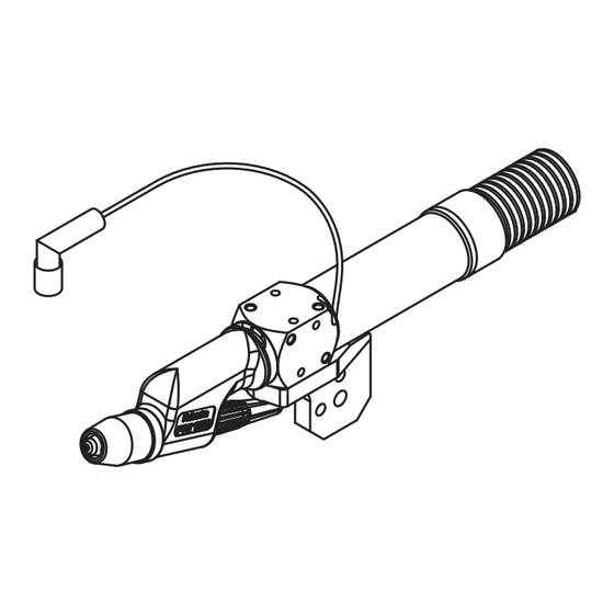
Plasmalöten bis zu einer Materialstärke von 1,5 mm (PTW 500), 3 mm (PTW 1500) und 8 mm (PTW 3500). Die Schweißbrenner haben serienmäßig einen Fronius F++ Anschluss. Für den Betrieb an einem handelsüblichen Plasma-Gerät stehen verschiedene Adapter zur Verfügung. - Page 8 Plasmadüse ∅ 3,2 mm Einstell-Lehre Schutzgasdüse Keramik-Zentrierrohr Anschluss für Abschalt-Box Brennerkörper Wasserbügel mit Anschlagring Schlauchpaket 4 m, Fronius F++ / FG Anschluss Brennerkappe Robacta PTW 3500 Spannhülse ∅ 4,8 mm Wolframelektrode WL 15, ∅ 4,8 mm Halterung Lieferumfang Robacta PTW 3500...
-
Page 9: Optionen Ptw 500
Optionen PTW Option Heißdraht Plasmadüse 0,6 / 0,8 / 1,0 / 1,4 / 1,6 mm Adapter für das nicht digitale PlasmaModul Kaltdrahtzuführung mit Antrieb (Push-Pull-System): Robacta Plasma KD Drive Kaltdrahtzuführung (Push-System): Robacta Plasma KD Schleppgasdüse 50 / 100 mm Einstell-Lehre ∅ 1,5 - 2 mm Optionen PTW 1500 Kaltdrahtzuführung mit Antrieb (Push-Pull-System): Robacta Plasma KD Drive... -
Page 10: Robacta Ptw 500, 1500, 3500 Montieren
Robacta PTW 500, 1500, 3500 montieren Sicherheit WARNUNG! Fehlerhaft durchgeführte Arbeiten können schwerwiegende Personen und Sachschäden verursachen. Nachfolgend beschriebene Tätigkei- ten dürfen nur von geschultem Fachpersonal durchgeführt werden! Beachten Sie die Sicherheitsvorschriften. Robacta PTW 500 montieren 2x360° Wolframelektrode einsetzen Spannhülse einsetzen Wichtig! Die Wolframelektrode so einsetzen, dass die Spitze ca. -
Page 11: Robacta Ptw 1500 Montieren
Robacta PTW 1500 montieren Wolframelektrode einsetzen Halterung montieren, Spannhülse einsetzen Wichtig! Die Wolframelektrode so einsetzen, dass die Spitze ca. 10 mm aus dem Brennerkörper ragt. Brennerkappe leicht anziehen, die Wolframelektrode sollte im Brennerkörper noch verschiebbar sein. Wichtig! Auf korrekte Einstellung der Wolframelektrode achten (siehe Kapitel „Wolframelektrode einstellen“) max. - Page 12 Robacta PTW Wichtig! Die Wolframelektrode so einsetzen, dass die Spitze ca. 10 mm aus dem 3500 montieren Brennerkörper ragt. Brennerkappe leicht anziehen, die Wolframelektrode sollte im Brennerkörper noch verschiebbar sein. Wassergekühlte Schutz-Gasdüsen müs- sen an den Wasseranschlüssen ange- schlossen werden. Keramische Schutz-Gasdüsen benötigen keine Wasserkühlung.
-
Page 13: Wolframelektrode Einstellen
Wolframelektrode einstellen Allgemeines Die Position der Wolframelektrode ist neben der eingestellten Plasmagas-Menge aus- schlaggebend für die Belastungsgrenzen. Unter Belastungsgrenzen versteht man den maximal möglichen Schweißstrom bei einer bestimmten Plasmadüse, bei einer bestimmten Plasmagas-Menge, bei einer bestimmten Position der Wolframelektrode. Der Einstell-Vorgang für die Wolframelektrode zum Plasma-Schweißen / Plasma-Löten wird im folgenden Abschnitt beschrieben. -
Page 14: Einstell-Lehre Ptw 1500 Justieren
Wolframelektrode einstellen PTW (Fortsetzung) Einstell-Lehre HINWEIS! Die Standard-Einstel- PTW 1500 justie- lung für das Maß „x“ an der jeweiligen Einstell-Lehre ist abhängig vom Durchmesser der Plasmadüse. Standard-Einstel- lung für das Maß „x“ gemäß folgender Tabelle einstellen: ∅ ∅ ∅ ∅ ∅ Plasmadüse „x“... -
Page 15: Wolframelektrode Einstellen Ptw 3500
Wolframelektrode einstellen PTW 1500 (Fortsetzung) max. 3 Nm ... und Wolframelektrode einrichten Wolframelektrode mittels Brennerkappe fixieren Wolframelektrode einstellen PTW 3500 Brennerkappe lockern - je nach Brennerstellung Einstell-Lehre an der Plasmadüse ansetzen ... darauf achten, dass die Wolframelektrode nicht aus dem Plasmabrenner fällt! ... -
Page 16: Inbetriebnahme
Inbetriebnahme Allgemeines WARNUNG! Fehlbedienung kann schwerwiegende Personen- und Sachschä- den verursachen. Beschriebene Funktionen erst anwenden, wenn folgende Dokumente vollständig gelesen und verstanden wurden: diese Bedienungsanleitung sämtliche Bedienungsanleitungen der Systemkomponenten, insbesondere Sicherheitsvorschriften Bestimmungsge- Der Plasmabrenner ist ausschließlich zum Plasma-Schweißen und Plasma-Löten mäße Verwen- bestimmt. - Page 17 Inbetriebnahme Bei Erstinbetriebnahme auf korrekte Gasströmung achten (Fortsetzung) Plasmabrenner positionieren (Roboter einrichten) Schutzgas und Plasmagas für mindestens 30 sec. spülen HINWEIS! Der Plasmabrenner muss während des Betriebes ständig gekühlt werden. Kühlkreislauf der Plasma-Anlage auf richtige Funktion überprüfen, Kühlgerät auf Dauerbetrieb einstellen (z.B.: SetUp-Menü an der Stromquelle, Parameter C-C = ON) HINWEIS! Ein Zünden des Pilotlichtbogens ohne voreingestelltes Plasmagas kann die Verschleißteile Plasmadüse, Keramik-Zentrierrohr und Wolframelek-...
-
Page 18: Belastungsgrenzen In Abhängigkeit Von Der Plasmagas-Menge
Belastungsgrenzen in Abhängigkeit von der Plasma- gas-Menge Allgemeines Belastungsgrenzen beim Plasmaschweißen / Plasmalöten hängen von folgenden Fakto- ren ab: Durchmesser der Plasmadüse Position der Wolframelektrode Plasmagas-Menge Die folgenden Belastungsgrenzen gelten bei Standard-Einstellung der Wolframelektrode (siehe auch Abschnitt „Wolframelektrode einstellen“). Belastungsgren- Zum Plasmaschweißen müssen die eingestellten Werte für Plasmagas-Menge und zen in Abhängig- maximalen Schweißstrom innerhalb der angegebenen Grenzwerte liegen. -
Page 19: Beispiel Belastungsgrenze (Ptw 1500)
Belastungsgren- Tabelle gilt nur für PTW 3500 in Verbindung mit einem FK9000 Kühlgerät: zen in Abhängig- ∅ ∅ ∅ ∅ ∅ Plasmadüse Plasmagas-Menge max. Schweißstrom keit von der 2,0 mm min. 1,0 l/min 170 A Plasmagas- 2,5 mm min. 1,0 l/min 190 A Menge (Fortsetzung) -
Page 20: Fehlerdiagnose - Fehlerbehebung
Fehlerdiagnose - Fehlerbehebung Sicherheit WARNUNG! Ein elektrischer Schlag kann tödlich sein. Vor Arbeiten am Plas- mabrenner: Netzschalter von Stromquelle und Plasmagerät in Stellung „O“ schalten Stromquelle und Plasmagerät vom Netz trennen ein verständliches Warnschild gegen Wiedereinschalten anbringen Fehlerdiagnose - Pilot-Lichtbogen zündet nicht Fehlerbehebung Ursache: Wolframelektrode fehlt... -
Page 21: Pflege, Wartung Und Entsorgung
Pflege, Wartung und Entsorgung Allgemeines Regelmäßige und vorbeugende Wartung des Plasmabrenners sind wesentliche Fakto- ren für einen störungsfreien Betrieb. Der Plasmabrenner ist hohen Temperaturen ausge- setzt. Daher benötigt der Plasmabrenner eine häufigere Wartung als andere Komponen- ten einer Plasma-Schweißanlage. WARNUNG! Ein elektrischer Schlag kann tödlich sein. Vor Arbeiten am Plas- mabrenner: Netzschalter von Stromquelle und Plasmagerät in Stellung „O“... -
Page 22: Technische Daten
5,5 bar 5,5 bar 5,5 bar 79,74 psi 79,74 psi 79,74 psi Kühlmittel-Mindestdurchfluss 1,0 l/min 1,0 l/min 1,0 l/min *) Flüssigkeitskühlung **) Original Fronius-Kühlmittel ***) Geringste Kühlleistung laut Norm IEC 60974-2 Das Produkt entspricht den Anforderungen laut Norm IEC 60974-7... - Page 23 Read the manual carefully and you will soon be familiar with all the many great features of your new Fronius product. This really is the best way to get the most out of all the advantages that your machine has to offer.
- Page 25 PTW 500 options ............................. 5 PTW 1500 options ........................... 5 PTW 3500 options ........................... 5 Assembling the Robacta PTW 500, 1500, 3500 ................... 6 Safety ............................... 6 Assembling the Robacta PTW 500 ......................6 Assembling the Robacta PTW 1500 ......................7 Assembling the Robacta PTW 3500 ......................
-
Page 26: General
Machine concept (Cold) wire feeder Robacta Plasma KD Drive Robacta PTW 500 Robacta PTW 500 with Robacta Plasma KD Drive and wirefeed options (Cold) wire feeder Robacta Plasma KD Drive Robacta PTW 1500 Robacta PTW 1500 with Robacta Plasma KD Drive and wirefeed options... -
Page 27: Applications
1.5 mm (PTW 500), 3 mm (PTW 1500) and 8 mm (PTW 3500). The welding torches have a Fronius F++ connection as standard. Various adapters are available to enable the torches to be operated with any standard plasma device. Each torch can be equipped with KD Drive, a pushed wire-feed unit or a drag gas nozzle. - Page 28 Connection for cut-out box Torch body stopper with stop ring Hosepack 4 m, Fronius F++ / FG connection Robacta PTW 3500 torch cap Clamping sleeve ∅ 4.8 mm Tungsten electrode WL 15, ∅ 4.8 mm Holder Robacta PTW 3500 scope of supply...
-
Page 29: Ptw 500 Options
PTW 500 options Hot wire option Plasma nozzle 0.6 / 0.8 / 1.0 / 1.4 / 1.6 mm Adapter for the non-digital PlasmaModul Cold wire feeder with drive (push-pull system): Robacta Plasma KD Drive Cold wire feeder (push system): Robacta Plasma KD Drag gas nozzle 50 / 100 mm Adjusting gauge ∅... -
Page 30: Assembling The Robacta Ptw 500, 1500, 3500
Assembling the Robacta PTW 500, 1500, 3500 Safety WARNING! Work that is carried out incorrectly can cause serious injury and damage. The following activities must only be carried out by trained and quali- fied personnel. Follow the safety regulations. Assembling the Robacta PTW 500 2x360°... -
Page 31: Assembling The Robacta Ptw 1500
Assembling the Robacta PTW 1500 Insert tungsten electrode Fit holder, insert clamping sleeve Important! Insert the tungsten electrode so that the tip protrudes approx. 10 mm out of the torch body. Slightly tighten the torch cap so that the tungsten electrode can still move inside the torch body. - Page 32 Assembling the Important! Insert the tungsten electrode so that the tip protrudes approx. 10 mm out of Robacta PTW the torch body. Slightly tighten the torch cap so that the tungsten electrode can still move 3500 inside the torch body. Water-cooled protective gas nozzles must be connected to the water connections.
-
Page 33: Adjusting The Tungsten Electrode
Adjusting the tungsten electrode General Alongside the specified plasma gas flow rate, the position of the tungsten electrode plays a crucial role in determining the loading limits. By loading limits we mean the maximum possible welding current for a particular plasma nozzle, for a particular plasma gas flow rate, for a particular tungsten electrode position. -
Page 34: Calibrating The Ptw 1500 Adjusting Gauge
Adjusting the PTW 500 tungs- ten electrode (continued) Calibrating the NOTE! The standard setting for PTW 1500 adjus- measurement „x“ on the adjusting ting gauge gauge depends on the diameter of the plasma nozzle. Refer to the following table when adjusting the standard setting for measurement „x“: ∅... -
Page 35: Adjusting The Ptw 3500 Tungsten Electrode
Adjusting the PTW 1500 tungs- ten electrode (continued) max. 3 Nm ... and adjust tungsten electrode Fix the tungsten electrode in place using the torch Adjusting the PTW 3500 tungs- ten electrode Loosen the torch cap - caution, the tungsten Place adjusting gauge onto plasma nozzle ... -
Page 36: Start-Up
Start-up General WARNING! Operating the equipment incorrectly can cause serious injury and damage. Do not use the functions described until you have thoroughly read and understood the following documents: these Operating Instructions all the operating instructions for the system components, especially the safety rules Proper use The plasma torch is intended exclusively for plasma welding and plasma brazing. - Page 37 Start-up When starting up for the first time, make sure the gas flow is correct (continued) Position plasma torch (adjust robot) Purge shielding gas and plasma gas for at least 30 seconds NOTE! The plasma torch must be cooled constantly during operation. Check that the cooling circuit on the plasma machine is functioning correctly, set the cooling unit to permanent operation (e.g.
-
Page 38: Loading Limits Dependent On The Plasma Gas Flow Rate
Loading limits dependent on the plasma gas flow rate General Loading limits for plasma welding/plasma brazing depend on the following factors: Diameter of the plasma nozzle Position of the tungsten electrode Plasma gas flow rate The following loading limits apply to the standard tungsten electrode setting (see also „Adjusting the tungsten electrode“). - Page 39 Loading limits ∅ ∅ ∅ ∅ ∅ Plasma nozzle Plasma gas flow rate Max. welding current dependent on the 2.0 mm min.1.0 l/min 170 A plasma gas flow 2.5 mm min.1.0 l/min 190 A rate (continued) 3.2 mm min.1.0 l/min 210 A 3.5 mm min.1.0 l/min...
-
Page 40: Troubleshooting
Troubleshooting Safety WARNING! An electric shock can be fatal. Before carrying out any work on the plasma torch: Switch the power source and plasma device mains switch to the „O“ position Disconnect power source and plasma device from the mains Put up an easy-to-understand warning sign to stop anybody inadvertently switching it back on again Troubleshooting... -
Page 41: Care, Maintenance And Disposal
Care, maintenance and disposal General Regular and preventive maintenance of the plasma torch is essential for problem-free operation. The plasma torch is subjected to high temperatures. The plasma torch there- fore requires more frequent maintenance than other components in a plasma welding system. -
Page 42: Technical Data
5.5 bar 79.74 psi 79.74 psi 79.74 psi Minimum coolant flowrate 1.0 l/min 1.0 l/min 1.0 l/min *) Liquid cooling **) Original Fronius coolant ***) Minimum cooling power in accordance with standard IEC 60974-2 The product complies with standard IEC 60974-7... -
Page 43: Cher Lecteur
Introduction Nous vous remercions de votre confiance et vous félicitons d’avoir acheté un produit de qualité supérieure de Fronius. Les instructions suivantes vous aideront à vous familiari- ser avec le produit. En lisant attentivement les instructions de service suivantes, vous découvrirez les multiples possibilités de votre produit Fronius. - Page 45 Livraison ..............................3 Options PTW 500............................. 5 Options PTW 1500 ........................... 5 Options PTW 3500 ........................... 5 Montage Robacta PTW 500, 1500, 3500 ...................... 6 Sécurité ..............................6 Montage Robacta PTW 500 ........................6 Montage Robacta PTW 1500 ........................7 Montage Robacta PTW 3500 ........................
-
Page 46: Généralités
Guide-fil (froid) Robacta Plasma KD Drive l’appareil Robacta PTW 500 Robacta PTW 500 avec les options Robacta Plasma KD Drive et guide-fil Guide-fil (froid) Robacta Plasma KD Drive Robacta PTW 1500 Robacta PTW 1500 avec les options Robacta Plasma KD Drive et guide-fil... -
Page 47: Domaines D'application
(suite) 1,5 mm (PTW 500), 3 mm (PTW 1500) et 8 mm (PTW 3500). De série, les torches sont équipées d’un raccord Fronius F++. Divers adaptateurs sont disponibles pour utilisation sur un appareil plasma usuel du commerce. Chaque torche peut être équipée avec KD Drive, d’une avance KD ou d’une buse à gaz de traînage. - Page 48 Corps de torche Flexible de liaison déconnexion avec bague de butée Faisceau de liaison 4 m Raccord Fronius F++ / FG Cache de torche Robacta PTW 3500 Douille de serrage ∅ 4,8 mm Électrode tungstène WL 15, ∅ 4,8 mm Support...
-
Page 49: Options Ptw 500
Options PTW 500 Option fil chaud Buse plasma 0,6 / 0,8 / 1,0 / 1,4 / 1,6 mm Adaptateur pour le PlasmaModul non numérique Alimentation de fil froid avec entraînement (système Push-Pull) : Robacta Plasma KD Drive Alimentation de fil froid (système Push) : Robacta Plasma KD Buse à... -
Page 50: Montage Robacta Ptw 500, 1500, 3500
Montage Robacta PTW 500, 1500, 3500 Sécurité AVERTISSEMENT ! Les erreurs en cours d’opération peuvent entraîner des dommages corporels et matériels graves. Les opérations décrites ci-après doivent être effectuées exclusivement par du personnel qualifié et formé ! Respectez les consignes de sécurité. -
Page 51: Montage Robacta Ptw 1500
Montage Robacta PTW 1500 Mise en place de l’électrode en tungstène Montage du support, mise en place de la douille de serrage Important ! Insérer l’électrode de tungstène de manière à ce que la pointe dépasse d’env. 10 mm hors du corps de la torche. Tirer légèrement le cache de torche, l’électrode en tungstène doit encore pouvoir coulisser dans le corps de torche. -
Page 52: Montage Robacta
Montage Robacta Important ! Insérer l’électrode de tungstène de manière à ce que la pointe dépasse PTW 3500 d’env. 10 mm hors du corps de la torche. Tirer légèrement le cache de torche, l’électrode en tungstène doit encore pouvoir coulisser dans le corps de torche. Les buses gaz de protection refroidies par eau doivent être branchées sur les rac- cords d’eau. -
Page 53: Régler L'électrode De Tungstène
Régler l’électrode de tungstène Généralités Outre la quantité de plasma de gaz paramétrée, la position de la torche plasma est déterminante pour les limites de charge. Par limites de charge, on entend l’intensité de courant maximale possible pour une buse plasma déterminée, pour une quantité... -
Page 54: Régler L'électrode En Tungstène Ptw 500
Régler l’électrode en tungstène PTW 500 (suite) Ajuster le gabarit REMARQUE ! Le réglage de de réglage PTW base pour la mesure « X » sur le 1500 gabarit de réglage correspondant est fonction du diamètre de la buse plasma. Ajuster le réglage de base pour la mesure «... -
Page 55: Régler L'électrode En Tungstène Ptw 3500
Régler l’électrode en tungstène PTW 1500 (suite) max. 3 Nm ... et régler l’électrode en tungstène Fixer l’électrode en tungstène à l’aide du cache de torche Régler l’électrode en tungstène PTW 3500 Desserrer la cache de torche - en fonction de la Mettre en place le gabarit de réglage sur la buse position de la torche, veiller à... -
Page 56: Mise En Service
Mise en service Généralités AVERTISSEMENT ! Les erreurs de manipulation peuvent entraîner des dommages corporels et matériels graves. N’utiliser les fonctions décrites qu’après avoir lu et compris l’intégralité des documents suivants : les présentes Instructions de service toutes les Instructions de service des composants du système, en particu- lier les consignes de sécurité... - Page 57 Mise en service Lors de la première mise en service, veiller au bon débit du gaz (suite) Positionner la torche plasma (mettre en place le robot) Rincer au gaz de protection et au plasma de gaz pendant au moins 30 sec REMARQUE ! Durant le fonctionnement, la torche plasma doit être refroidie en permanence.
-
Page 58: Limites De Charge En Fonction De La Quantité De Plasma De Gaz
Limites de charge en fonction de la quantité de plas- ma de gaz Généralités Les limites de charge lors du soudage à l’arc plasma / du brasage plasma dépendent des facteurs suivants : diamètre de la buse plasma position de l’électrode en tungstène quantité... - Page 59 Limites de char- Tableau uniquement valable pour PTW 3500 en combinaison avec un refroidisseur ge en fonction de FK9000 : la quantité de ∅ ∅ ∅ ∅ ∅ Buse plasma Quantité de plasma de gaz Intensité de soudage max. plasma de gaz 2,0 mm min.
-
Page 60: Diagnostic D'erreur - Élimination De L'erreur
Diagnostic d’erreur - Élimination de l’erreur Sécurité AVERTISSEMENT ! Un choc électrique peut être mortel. Avant tous travaux sur la torche plasma : mettre l’interrupteur d’alimentation de la source de courant et de l’appareil plasma sur « O » déconnecter la source de courant et l’appareil plasma du réseau apposer un panneau d’avertissement compréhensible afin de prévenir toute remise en marche Diagnostic... -
Page 61: Maintenance, Entretien Et Élimination
Maintenance, entretien et élimination Généralités Un entretien régulier et préventif de la torche plasma constitue un facteur important permettant d’en garantir le bon fonctionnement. La torche plasma est soumise à des températures élevées. Elle nécessite donc une maintenance plus fréquente que les autres composants d’une installation de soudage plasma. -
Page 62: Caractéristiques Techniques
79,74 psi Débit minimal de réfrigérant 1,0 l/min 1,0 l/min 1,0 l/min *) Refroidissement par liquide **) Réfrigérant d’origine Fronius ***) Puissance de refroidissement minimale conformént à la norme IEC 60974-2 Ce produit satisfait aux exigences de la norme IEC 60974-7... - Page 63 ud_fr_st_et_01482 012007...
- Page 70 2x360°...
- Page 71 max. 3 Nm...
- Page 73 2x360°...
- Page 75 max. 3 Nm...
- Page 82 _ ˛...
- Page 83 Fronius o wysokiej jakości technicznej. Niniejsza instrukcja obsługi pomoże Państwu się z nim zaznajomić. Czytając uważnie instrukcję, poznają Państwo szeroki zakres zasto- sowań niniejszego produktu firmy Fronius. Tylko w ten sposób mogą Państwo najlepiej wykorzystać zalety produktu. Prosimy również o przestrzeganie przepisów bezpieczeństwa, by zapewnić większe bezpieczeństwo w miejscu użytkowania produktu.
- Page 85 Zakres dostawy ............................3 Opcje PTW 500 ............................5 Opcje PTW 1500 ............................5 Opcje PTW 3500 ............................5 Monta¿ Robacta PTW 500, 1500, 3500 ......................6 Bezpieczeñstwo ............................6 Monta¿ Robacta PTW 500 ........................6 Monta¿ Robacta PTW 1500 ........................7 Monta¿...
-
Page 86: Informacje Ogólne
Doprowadzenie drutu Robacta Plasma KD Drive urz¹dzenia (zimnego) Robacta PTW 500 Robacta PTW 500 z opcjami Robacta Plasma KD Drive i doprowadzaniem drutu Doprowadzenie drutu Robacta Plasma KD Drive (zimnego) Robacta PTW 1500 Robacta PTW 1500 z opcjami Robacta Plasma KD Drive i doprowadzaniem drutu... -
Page 87: Zakres Dostawy
1,5 mm (PTW 500), 3 mm (kontynuacja) (PTW 1500) i 8 mm (PTW 3500). Palniki spawalnicze s¹ seryjnie wyposa¿one w przy³¹cze Fronius F++. W celu umo¿liwienia eksploatacji z typowymi, dostêpnymi na rynku urz¹dzeniami plazmowymi, do dyspozycji s¹ odpowiednie adaptery. Ka¿dy palnik spawalniczy mo¿na wyposa¿yæ w KD-Drive, wsuwany zimny drut lub dyszê... - Page 88 Przy³¹cze do skrzynki Korpus palnika spawalniczego od³¹czaj¹cej z pierœcieniem mocuj¹cym Pa³¹k wodny Wi¹zka uchwytu 4 m, Przy³¹cze Fronius F++ / FG Kapturek palnika spawalniczego Robacta PTW 3500 Nakrêtka mocuj¹ca Α 4,8 mm Elektroda wolframowa WL 15, Α 4,8 mm Uchwyt...
-
Page 89: Opcje Ptw 500
Opcje PTW 500 opcja gor¹cego drutu dysza plazmowa 0,6 / 0,8 / 1,0 / 1,4 / 1,6 mm adapter do modu³u plazmowego analogowego doprowadzenie zimnego drutu (system Push-Pull): Robacta Plasma KD Drive doprowadzenie zimnego drutu (system Push): Robacta Plasma KD dysza os³ony gazowej wleczonej 50 / 100 mm sprawdzian nastawczy Α... -
Page 90: Monta¿ Robacta Ptw 500, 1500, 3500
Monta¿ Robacta PTW 500, 1500, 3500 Bezpieczeñstwo OSTRZE¿ENIE! Nieprawid³owo wykonane prace mog¹ spowodowaæ powa¿ne obra¿enia oraz szkody materialne. Poni¿ej opisane czynnoœci mo¿e wykonywaæ tylko przeszkolony personel specjalistyczny! Nale¿y przestrzegaæ przepisów bezpieczeñstwa. Monta¿ Robacta PTW 500 2x360° Wk³adanie elektrody wolframowej Wk³adanie nakrêtki mocuj¹cej Wa¿ne! Elektrodê... -
Page 91: Monta¿ Robacta Ptw 1500
Monta¿ Robacta PTW 1500 Wk³adanie elektrody wolframowej Monta¿ uchwytu, wk³adanie nakrêtki mocuj¹cej Wa¿ne! Elektrodê wolframow¹ nale¿y w³o¿yæ w taki sposób, aby jej czubek wystawa³ z korpusu palnika spawalniczego na ok. 10 mm. Doci¹gn¹æ lekko kapturek palnika spa- walniczego - elektroda wolframowa powinna jeszcze daæ siê przesun¹æ w korpusie palnika spawalniczego. - Page 92 Monta¿ Robacta Wa¿ne! Elektrodê wolframow¹ nale¿y w³o¿yæ w taki sposób, aby jej czubek wystawa³ z PTW 3500 korpusu palnika spawalniczego na ok. 10 mm. Doci¹gn¹æ lekko kapturek palnika spa- walniczego - elektroda wolframowa powinna jeszcze daæ siê przesun¹æ w korpusie palnika spawalniczego.
-
Page 93: Ustawianie Elektrody Wolframowej
Ustawianie elektrody wolframowej Informacje ogól- Pozycja elektrody wolframowej jest obok ustawionej iloœci gazu plazmotwórczego czynnikiem decyduj¹cym dla granic obci¹¿enia. Pod granicami obci¹¿enia rozumiany jest maksymalny mo¿liwy pr¹d spawania. w przypadku zastosowania okreœlonej dyszy plazmowej, w przypadku zastosowania okreœlonej iloœci gazu plazmotwórczego, w przypadku zastosowania okreœlonej pozycji elektrody wolframowej. -
Page 94: Wzorcowanie Sprawdzianu Nastawczego Ptw 1500
Ustawianie elektrody wolfra- mowej PTW 500 (kontynuacja) Wzorcowanie WSKAZÓWKA! Standardowe sprawdzianu ustawienie na wymiar „x“ w nastawczego przypadku danego sprawdzianu PTW 1500 nastawczego jest uzale¿nione od œrednicy dyszy plazmowej. Standardowe ustawienie na wymiar „x“ nale¿y ustawiæ korzystaj¹c z poni¿szej tabeli: Α... -
Page 95: Ustawianie Elektrody Wolframowej Ptw 3500
Ustawianie elektrody wolfra- mowej PTW 1500 (kontynuacja) max. 3 Nm ... i ustawienie elektrody Zamocowaæ elektrodê wolframow¹ za pomoc¹ kapturka palnika Ustawianie elektrody wolfra- mowej PTW 3500 Przy³o¿yæ sprawdzian nastawczy do dyszy plazmo- Poluzowaæ kapturek palnika - w zale¿noœci od ustawienia palnika zwracaæ... -
Page 96: Uruchamianie
Uruchamianie Informacje ogól- OSTRZE¿ENIE! Nieprawid³owa obs³uga mo¿e spowodowaæ powstanie powa¿nych obra¿eñ cia³a oraz szkód materialnych. Z opisanych funkcji mo¿na korzystaæ dopiero po dok³adnym zapoznaniu siê z nastêpuj¹cymi dokumentami: niniejsz¹ instrukcj¹ obs³ugi, wszystkimi instrukcjami obs³ugi elementów systemowych, szczególnie przepisami bezpieczeñstwa U¿ytkowanie Plazmowy palnik spawalniczy jest przeznaczony wy³¹cznie do spawania i lutowania plazmo- zgodne z przez- wego. - Page 97 Uruchamianie Przy pierwszym uruchomieniu nale¿y zwracaæ uwagê na prawid³owy przep³yw gazu (kontynuacja) Nadaæ plazmowemu palnikowi spawalniczemu w³aœciw¹ pozycjê (wyregulowaæ robota) P³ukaæ gazem ochronnym i gazem plazmotwórczym przez co najmniej 30 s WSKAZÓWKA! Podczas eksploatacji plazmowy palnik spawalniczy musi byæ stale ch³odzony. Skontrolowaæ...
-
Page 98: Granice Obci¹¿Enia W Zale¿Noœci Od Iloœci Gazu Plazmotwórczego
Granice obci¹¿enia w zale¿noœci od iloœci gazu plaz- motwórczego Informacje ogól- Granice obci¹¿enia przy spawaniu / lutowaniu plazmowym zale¿¹ od nastêpuj¹cych czynników: œrednicy dyszy plazmowej pozycji elektrody wolframowej iloœci gazu plazmotwórczego Poni¿ej podane granice obci¹¿eñ obowi¹zuj¹ przy standardowym ustawieniu elektrody wolframowej (patrz tak¿e ustêp „Ustawianie elektrody wolframowej“). - Page 99 Granice Α Α Α Α Α plazmowego palnika spawalniczego Iloœæ gazu plazmotwórczego maks. pr¹d obci¹¿enia w spawania zale¿noœci od 2,0 mm min. 1,0 l/min 170 A iloœci gazu 2,5 mm min. 1,0 l/min 190 A plazmotwórczego (kontynuacja) 3,2 mm min. 1,0 l/min 210 A 3,5 mm min.
-
Page 100: Diagnostyka I Usuwanie Usterek
Diagnostyka i usuwanie usterek Bezpieczeñstwo OSTRZE¿ENIE! Pora¿enie elektryczne mo¿e spowodowaæ œmieræ. Przed rozpoczêciem prac przy plazmowym palniku spawalniczym: wy³¹cznik zasilania Ÿród³a pr¹du spawalniczego i urz¹dzenia plazmowego ustawiæ w pozycji „O” Od³¹czyæ Ÿród³o pr¹du spawalniczego oraz urz¹dzenie plazmowe od sieci Umieœciæ wyraŸn¹ tabliczkê ostrzegaj¹c¹ przed ponownym w³¹czeniem Diagnostyka i Pilotuj¹cy ³uk spawalniczy nie zajarza siê... -
Page 101: Czyszczenie, Konserwacja I Utylizacja
Czyszczenie, konserwacja i utylizacja Informacje ogól- Regularne i profilaktyczne czyszczenie plazmowego palnika spawalniczego to wa¿ny czynnik dla bezawaryjnej eksploatacji. Plazmowy palnik spawalniczy jest wystawiony na dzia³anie bardzo wysokich temperatur. Z tego powodu wymaga on czêstszej konserwacji ni¿ pozosta³e podzespo³y plazmowego systemu spawania. OSTRZE¿ENIE! Pora¿enie elektryczne mo¿e spowodowaæ... -
Page 102: Dane Techniczne
5,5 bar 79,74 psi 79,74 psi 79,74 psi Minimalny przep³yw p³ynu ch³odz¹cego 1,0 l/min 1,0 l/min 1,0 l/min *) Ch³odzenie ciecz¹ **) Oryginalny p³yn ch³odz¹cy Fronius ***) Najni¿sza wydajnoœæ ch³odzenia wg normy IEC 60974-2 Produkt spe³nia wymogi normy IEC 60974-7... - Page 103 FRONIUS INTERNATIONAL GMBH Froniusplatz 1, A-4600 Wels, Austria Tel: +43 (0)7242 241-0, Fax: +43 (0)7242 241-3940 E-Mail: sales@fronius.com www.fronius.com www.fronius.com/addresses Under http://www.fronius.com/addresses you will find all addresses of our Sales & service partners and Locations. ud_fr_st_so_00082 012011...