Table des Matières
Publicité
Les langues disponibles
Les langues disponibles
Liens rapides
INSTALLATION INSTRUCTIONS
INSTALLATION INSTRUCTIONS
CARE AND USE MANUAL FOR:
NOTICE D'UTILISATION ET D'ENTRETIEN POUR:
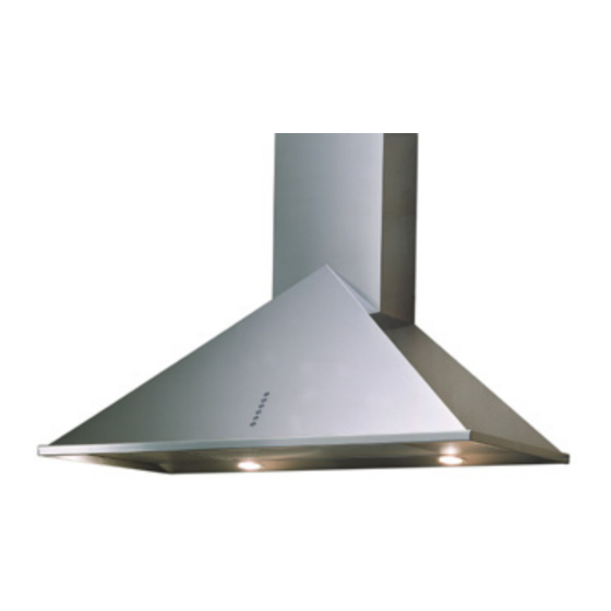
WALL RANGE HOODS
HOTTES MURALES
Models covered by this instructions - Notice d'instruction pour les modèles:
SU1 - SUE1 - SU2 - SU3 - SUE3 - SU10 - SU22
SU92 - SUTC92 - SU54
*** BEFORE INSTALLATION ***
ENSURE THERE IS NO VISIBLE OR HIDDEN DAMAGE SUSTAINED DURING SHIPPING
*** AVANT L'INSTALLATION ***
S'ASSURER QUE LES PRODUITS N'ONT SUBI AUCUN DOMMAGE PENDANT LE TRANSPORT
*** SHIPPING DAMAGE ***
MUST BE REPORTED WITHIN 5 DAYS OF RECEIPT
*** DOMMAGES DE TRANSPORT ***
DOIVENT ÊTRE NOTIFIÉS DANS LES 5 JOURS SUIVANT LA RÉCEPTION
Publicité
Chapitres
Table des Matières

Manuels Connexes pour Sirius SU1


Sommaire des Matières pour Sirius SU1
- Page 1 WALL RANGE HOODS HOTTES MURALES Models covered by this instructions - Notice d’instruction pour les modèles: SU1 - SUE1 - SU2 - SU3 - SUE3 - SU10 - SU22 SU92 - SUTC92 - SU54 *** BEFORE INSTALLATION *** ENSURE THERE IS NO VISIBLE OR HIDDEN DAMAGE SUSTAINED DURING SHIPPING *** AVANT L’INSTALLATION ***...
- Page 2 WAR NIN G Thank you for purchasing a Sirius Range Hood. Please read all the instructions in this manual before installing the appliance. Save these instructions for future reference. Only use this appliance as an exhaust ventilation system for the removal of coo- king vapors.
-
Page 3: Table Des Matières
TABLE OF CONTENTS BEFORE YOU BEGIN DUCTING External Venting Requirements Duct Run Calculation ELECTRICAL Electrical Supply INSTALLATION Positioning the Range Hood Marking the Fixing Holes for the Range Hood Fixing the Main Support Bracket Chimney installation Hanging the Range Hood Connecting Electricity and Ducting Connecting Chimneys Re-Circulating Requirements... -
Page 4: Before You Begin
B E F OR E Y OU B E G I N The manufacturer declines all responsibility BEFORE YOU BEGIN: It is advisable to test in the event of failure to observe the instruc- run the range hood before installation. tions given here for installation, maintenan- ce and suitable operation of the product. -
Page 5: Electrical
Maximum Run 6” or 3 1/4 x 10” duct * 100 FT Deduct Each 90 elbow used 15FT Each 45 elbow used Each 6” or 3 1/4 x 10” duct Transition used fig. 2 Each 3” 1/4 x 10” to 6” Range hoods may interrupt the proper flow of Transition used combustion gases from fireplaces, gas furna-... -
Page 6: Installation
I N S TA L L AT IO N Positioning the Range Hood. Using a sharp object, mark the wall through Determine the center point of the range hood. the template at the center point of the three This is generally the center of the range. Make holes. - Page 7 Before installing the hood is necessary to And fix the box to the just-fit union with two fix the tow motor air outlet union with the screws. screws that are in the accessory bag. Then open the upper cover of the power box.
-
Page 8: Chimney Installation
Chimney Installation. The bracket fixed onto the back of the range Locate the bracket (Fig. 2Y) and position hood will drop into the channel on the top of it with the vertical axis (marked on the wall bracket “S” on the wall. Ensure the hood is earlier) running through the midpoint of bra- securely engaged into the support bracket cket “Y”. -
Page 9: Connecting Chimneys
fig. 8 fig. 10 Connect the appropriate length of ducting to the fan exhaust point and join up with the Do not fix the ducting to the range hood ducting to the exterior. exhaust outlet with screws-use duct tape. Use duct tape on all joints. Figure 9 shows venting directly through the wall. -
Page 10: Re-Circulating Requirements
fig. 12 fig. 11 Re-Circulating Requirements. If the unit is to be used in the re-circulating mode, fit the carbon filter after the installa- tion is complete (refer to Figure 12) fit the deflector (refer Figure 13) with the screws supplied to the upper telescope chimney. -
Page 11: Operating Procedures
O PE R AT I N G PR O C E DU RES Read all the instructions before operating FUNCTION the appliance. Save these instructions for future reference. “SU Models Manual touch buttons Fig. 15” General Advice. A: Light ON/OFF button Ensure that the grease filters are in place. -
Page 12: Radio Control
RC001 TC models (SUTC92) A: Light switch On/Off ADIO ONTROL B: Reduce speed Radio control used for the remote operation of C: Luminous telltale ducted cooker hoods. D: Increase speed TECHNICAL DATA E: 10 - minute timer - Alkaline battery powered: 12 V mod. 27A - Operating frequency: 433.92 Mhz The touch control key allows the function de- - Combinations: 32.768... - Page 13 Generating a new transmission code: WARNING The radio control system is provided with preset The battery should be replaced every year to codes. Should new codes be required, proceed guarantee the optimal range of the transmitter. as follows: Press simultaneously buttons: To replace the exhausted battery, take the pla- stic lid off, remove the battery and replace it with a new one, observing the correct battery...
-
Page 14: Maintenance
SU Models only: Filter requires washing in- Use the low speeds for normal use and the dicator After 30 hours of use, all the buttons higher speeds for strong odors and fumes. will light up to remind you that the grease fil- ter should be cleaned. -
Page 15: Substitution Of The Led Bar
(If in doubt, call 866.528.4987) FOR SU92 Substitution of the LED bar: FOR SU1 – SUE1 - SU2 - SU3 - SUE3 - Using an appropriate tool, remove the LED SU10 - SU22 - SU54 bar from its seat (refer to Fig. 21), disconnect it electronically using the appropriate con- To replace the round LED lamps (fig.20) you... -
Page 16: Who Is Covered
ONE YEAR PARTS & SERVICE REPAIR WARRANTY: During the first year from date of original purchase, Sirius will, at its option, repair or replace, without charge, any product or part which is found to be defective under normal use and service. -
Page 17: Instructions Importantes Pourla Sécurité
INSTRUCTIONS IMPORTANTES POURLA SÉCURITÉ Merci d’avoir choisi une Hotte de Cuisine Sirius. Veuillez lire attentivement toutes les instructions avant l’installation et l’utilisation de l’appareil. Conservez ces instructions afin de pouvoir les consulter au besoin. Cet appareil est destiné à la ventilation générale seulement. NE L’UTILISEZ PAS pour évacuer des vapeurs ou des substances dangereuses ou explosives. - Page 18 TABLE DES MATIÈRES AVANT DE COMMENCER CONDUIT Version Évacuation Extérieure Calcul Longueur Conduit ÉLECTRICITÉ Alimentation Électrique INSTALLATION Positionnement de la Hotte Perçage du Mur pour le Positionnement de la Hotte Fixation Étrier de Support Principal Installation de la Cheminée Accrochage de la Hotte Branchement Électrique et Conduit Raccordement de la Cheminée Mode Recyclage...
-
Page 19: Avant De Commencer
AVAN T D E C OM M E NCE R Le fabricant décline toute responsabilité AVANT DE COMMENCER : On conseille de en cas de dommages causés par un non vérifier le fonctionnement de la hotte avant respect des instructions d’installation, d’uti- son installation. -
Page 20: Électricité
Maximum Run 6” or 3 1/4 x 10” duct * 100 FT Deduct Each 6” or 8” 90 elbow used 15FT Each 6” or 8” 45 elbow used Each 6” or 8” or 3 1/4 x 10” duct Transition used fig. -
Page 21: Installation
I N S TA L L ATIO N Positionnement de la Hotte. Utilisez un outil pointu, marquez le mur par le Déterminez le centre de la hotte. Marquez gabarit au point milieu des trois trous. Au bas d’une croix sur le mur la hauteur de 25” si du gabarit, il y a trois séries de deux trous. - Page 22 Avant d’installer la hotte, il est nécessaire de et fixez la boîte avec les deux vis dans le fixer le raccord de sortie d’air à deux moteu- raccord qui vient d’être monté. rs avec les vis qui se trouvent dans le sachet des accessoires.
-
Page 23: Installation De La Cheminée
Seulement pour SU202 – SU208 L’étrier fixé à la partie postérieure de la hotte se glisse dans la rainure de la partie Montez les éléments “C” avant de position- supérieure de l’étrier de support “S” du mur. ner la hotte – voir figure 5 pour son position- Assurez-vous que la hotte est correctement nement. -
Page 24: Raccordement De La Cheminée
fig. 8 Raccordez le conduit de longueur appropriée fig. 10 à la sortie d’air du ventilateur et puis au con- duit qui porte à l’extérieur. Ne fixez jamais le conduit à la sortie d’éva- cuation de la hotte avec des vis – utilisez La figure 9 montre l’évacuation à... -
Page 25: Mode Recyclage
fig. 12 fig. 11 Mode Recyclage. Si vous utilisez l’appareil en mode recyclage, insérez les filtres à charbon une fois l’installa- tion complétée (voir Fig. 12). Fixez le déflecteur (voir Fig. 13) avec les vis à la partie supérieure du télescope de la che- minée. -
Page 26: Recommandations Générales
O PE R AT I N G PR O C E DU RES Lisez attentivement toutes les instructions FONCTIONS avant cette opération. Conservez ces instruc- tions afin de pouvoir les consulter au besoin. “SU Models Fig.15” Recommandations Générales. A: Touche lumière ON/OFF Assurez-vous que les filtres sont en place. -
Page 27: Caractéristiques Techniques
TC modèles (SU92 – SU97) ADIOCOMMANDE A : Allumer et éteindre la lumière S6/S ÉRIE EFREE B : Diminuer la vélocité Radiocommande pour le pilotage à distance de C : Girouette lumineuse hottes. D : Augmenter la vélocité CARACTÉRISTIQUES TECHNIQUES E : Minuteur de 10 minutes - Alimentation par pile alcaline: 12V mod. - Page 28 Génération d’’un nouveau code de transmis- Touche d’arrêt d’urgence : sion : En cas de dysfonctionnement de la radiocom- La radiocommande est fournie par l’usine avec mande, utilisez le bouton d’arrêt d’urgence pour des codes prédéfinis. Si vous désirez générer de éteindre l’appareil.
-
Page 29: Entretien
Seulement pour modèle SU: après 30 Utilisez les vitesses basses pour une utilisa- heures de fonctionnement de la hotte, tous tion normale et les vitesses élevées pour les les voyants clignotent pour vous rappeler odeurs fortes et les fumées. que les filtres à graisse doivent être net- toyés. -
Page 30: Replacement De La Barre Led
(Dans le doute, appelez le 866.528.4987) Pour SU92 – SU97 Replacement de la barre LED: POUR SU1 - SUE1 - SU2 - SU3 - SUE3 - En utilisant un outil approprié, enlever la bar- SU10 - SU22 - SU31 - SU36 - SU47-P - SU54 re LED de son siège (faites référence à... -
Page 32: Qui Est Couvert Par La Garantie
CANADA 1-800-463-2566 et fournissez le code du produit, la description du vice ou du défaut et la date d’achat du produit. Sirius se réser- ve le droit de demander une preuve d’achat. Sirius, à sa propre discrétion, rempla-cera les produits endommagés pendant le transport, à...