Publicité
Liens rapides
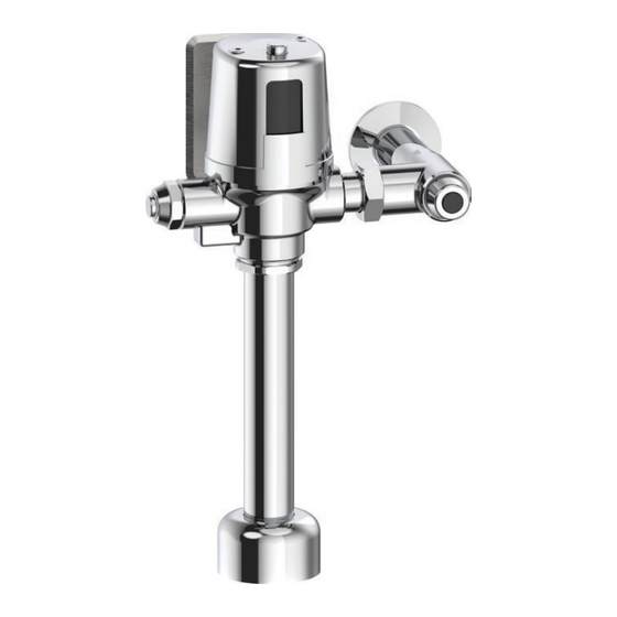
81T2-MMO Series -
Série 81T2-MMO -
Serie 81T2-MMO -
Model Configurations
Configurations du modèle
Configuraciones del modelo
Valve Type
Power Option
0 - Water Closet
11.5" (292 mm) oulet tube
2 - Water Closet
Option d'alimentation
24" (610 mm) outlet tube
3 - Urinal
13" (330 mm) oulet tube
Type de Soupape
Opción de alimentación
0 - Toilette - tube de sortie de
11,5 po (292 mm)
2 - Toilette - tube de sortie de
24 po (610 mm)
3 - Urinoir - tube de sortie de
Additional Options
13 po (330 mm)
(leave blank if not applicable)
Tipo de válvula
0 - Escusado - Tubo de salida
de 11.5" (292 mm)
Options additionnelles
2 - Escusado - Tubo de salida
de 24" (610 mm)
(laisser vide si elle ne s'applique pas)
3 - Mingitorio - Tubo de salida
de 13" (330 mm)
Opciones adicionales
(dejar en blanco si no corresponde)
NOTICE
Not all options are available on all base models.
AVIS
Les options ne sont pas toutes disponibles sur tous les modèles de base.
AVISO
No todas las opciones están disponibles en todos los modelos base.
81T201BTA-MMO
PLEASE LEAVE the Maintenance & Installation (M&I) manual with owner for maintenance and troubleshooting information.
VEUILLEZ LAISSER le Guide d'entretien et d'installation au propriétaire pour les informations d'entretien et de dépannage.
DEJE manual de mantenimiento e instalación con el dueño a fines de información de mantenimiento y resolución de problemas
Electronic Exposed Flush Valves
(with Manual Mechanical Override (MMO)
and H
Optics
®
2
Soupapes de chasse d'eau électroniques exposées
(avec contournement mécanique manuel (MMO) et la Technologie H
Válvulas de descarga electrónicas
(con anulación manual mecánica (MMO) y tecnología H
81T2
BT - Battery Operated
HW - Hardwired Operated
BT - Fonctionnement à piles
HW - Fonctionnement filé
BT - Funciona con baterías
HW - Funciona con conexión eléctrica
20 - Less Stop Assembly
30 - With Sloan®/Zurn® Tail
20 - Sans ensemble d'arrêts
30 - Avec tuyau Sloan
/Zurn
MD
MD
20 - Menos montaje de tope
30 - Con cola Sloan®/Zurn
81T201HWA-MMO
Technology)
0
1
BT
A - 20-
Flush Volumes
Adjustable Models
Water Closets - Blank - Factory Set 1.6 gpf (6.0 Lpf)
Urinals - Blank - Factory Set 0.5 gpf (1.9 Lpf)
Non-Adjustable Models
Water Closets
42 - Factory Set 1.1 gpf (4.2 Lpf)
48 - Factory Set 1.27 gpf (4.8 Lpf)
Urinals
05 - Factory Set 0.125 gpf (0.5 Lpf)
Volumes des chasses d'eau
Modèles réglables
Toilette - Par défaut - Réglage d'usine 1,6 gpf (6,0 Lpf)
Urinoir - Par défaut - Réglage d'usine 0,5 gpf (1,9 Lpf)
Modèles non réglables
Toilette
42 - Réglage d'usine 1,1 gpf (4,2 Lpf)
48 - Réglage d'usine 1,27 gpf (4,8 Lpf)
Urinoir
05 - Réglage d'usine 0,125 gpf (0,5 Lpf)
Volúmenes de descarga
Modelos ajustables
Escusado - En blanco - Ajuste de fábrica 1.6 gpf (6.0 Lpf)
Mingitorio - En blanco - Ajuste de fábrica 0.5 gpf (1.9 Lpf)
Modelos fijos no ajustables
Escusado
42 - Ajuste de fábrica 1.1 gpf (4.2 Lpf)
48 - Ajuste de fábrica 1.27 gpf (4.8 Lpf)
Mingitorio
05 - Ajuste de fábrica 0.125 gpf (0.5 Lpf)
81T231BTA-MMO
216039, Rev. D
Optics
2
48
-MMO-
CuVerro® Bactericidal
Surfaces
Blank - Non-Coated
CV - Coated on Electronic and
Mechanical Manual Override
Buttons
Surfaces bactéricides
CuVerro
MD
Par défaut - Non enduit
CV - Recouvrement sur les boutons
de commande électronique et de
commande manuelle mécanique
Superficies bactericidas
CuVerro®
Blank - Non-Coated
CV - Coated on Electronic and
Mechanical Manual Override
Buttons
Finish
Blank - Chrome
BL - Matte Black with Chrome Finish
Fini
Par défaut - Chrome
BL - Noir mat avec chrome
Acabado
En blanco - Cromado
BL - Negro mate con acabado cromado
81T231HWA-MMO
Optics
)
MD
2
)
®
CV
-
BL
Publicité

Manuels Connexes pour Delta Commercial TECK 81T2-MMO Serie


Sommaire des Matières pour Delta Commercial TECK 81T2-MMO Serie
- Page 1 81T2-MMO Series - Electronic Exposed Flush Valves (with Manual Mechanical Override (MMO) and H Optics Technology) ® Série 81T2-MMO - Soupapes de chasse d’eau électroniques exposées (avec contournement mécanique manuel (MMO) et la Technologie H Optics Serie 81T2-MMO - Válvulas de descarga electrónicas (con anulación manual mecánica (MMO) y tecnología H Optics ®...
- Page 2 Table of Contents echnical Data Dimensional Table (see Figure 1) Recommended Water Supply Water Closet Urinal To Prevent Water Hammer You May Need Installation Step 1. Supply Stop Installation . . . . . . . . . . . . . . . . . . . . . . . . . . . . . . . . . . . . . . . . . . . . . . . . . . . . . . . . . . . 7 (see Figure 2) Step 2.
- Page 3 Table des matières Données techniques Tableau des dimensions (voir Figure 1) Approvisionnement en eau recommandé Toilette Urinoir Pour prévenir le coup de bélier Articles dont vous pouvez avoir besoin Installation Étape 1. Installation de l’arrêt d’alimentation . . . . . . . . . . . . . . . . . . . . . . . . . . . . . . . . . . . . . . . . . . . . . . . . . . . 7 (voir Figure 2) Étape 2.
- Page 4 Índice de Contenidos Datos técnicos Tabla de dimensiones (consulte la Figura 1) Suministro de agua recomendado Escusado Mingitorio Para evitar el golpe de ariete Elementos que necesitará Instalación PASO 1. Instalación del tope de suministro . . . . . . . . . . . . . . . . . . . . . . . . . . . . . . . . . . . . . . . . . . . . . . . . 7 (consulte la Figura 2) PASO 2.
- Page 5 ECHNICAL DATA DONNÉES TECHNIQUES DATOS TÉCNICOS NOTICE Flush valve MUST be paired with a fixture of equivalent flush volume. AVIS La soupape de chasse DOIT être utilisée avec un dispositif de chasse d’eau de débit équivalent. AVISO La válvula de descarga DEBE emparejarse con un dispositivo de volumen de descarga equivalente. Dimensional Table (see Figure 1) Figure 1...
- Page 6 Suministro de agua recomendado Escusado Presión de flujo mínima: 25 psi (172 kPa), caudal mínimo: 25 gal/min (95 l/min) Mingitorio Presión de flujo mínima: 25 psi (172 kPa), caudal mínimo: 8 gal/min (30 l/min) AVISO • Recomendamos firmemente que se realicen cálculos del tamaño de las tuberías para garantizar el tamaño adecuado del suministro de agua. El diámetro mínimo de la línea de suministro depende de varios factores: la presión del agua, el tamaño y la longitud de la tubería, el número de unidades por baño y por edificio, el tipo de unidad, el factor de uso de la unidad, la elevación de la válvula por encima de la tubería principal, etc.
- Page 7 INSTALLATION INSTALLATION INSTALACIÓN Step 1. SUppLY StOp INStALLAtION (see Figure 2) Figure 2 WARNING It is important to FLUSH and thoroughly CLEAN water lines to 1.0” ELIMINATE contaminants (example - scale, sediment, gravel, cuttings, solder, (25mm) etc.). 1. Cut the end of the 1.0" (25mm) copper inlet tube (SO1 ) so that it is 1.0"...
- Page 8 Step 2. eLeCtRICAL BOX INStALL (“HW” Models Only) (see Figure 3) Figure 3 1. Install a 2" x 4" (51 x 102 mm) electrical box (E) into wall centered with the center of the fixture spud (SO2 ) and 1¾" (44 mm) above the center line of the angle stop (D).
- Page 9 Step 3. FLUSHOMeteR SIZING (see Figure 4) Figure 4 1. Assemble vacuum breaker components (G) into the outlet tube (I). 2. Attach the outlet tube (I) and vacuum breaker components (G) onto the flushometer body (F) secure with the coupling nut (H). 3.
- Page 10 Step 4. FLUSHOMeteR ASSeMBLY INStALLAtION (see Figure 5) Figure 5 1. Attach the outlet tube (I) and vacuum breaker components (G) onto the flushometer body (F) secure with the coupling nut (H). 2. Slide the flange spud flange (J) onto the outlet tube (I) 3.
- Page 11 Step 5. IF LeFt HAND StOp IS ReQUIReD (see Figure 6) Figure 6 Left Hand Inlet Right Hand Inlet 1. Remove the cover (F-4) by taking out the two cover screws (F-3). 2. You will now see the electronic compartment (F-5) and a cover gasket (F-6). Entrée de la main gauche Entrée de la main droite La entrada de mano izquierda...
- Page 12 Step 6. HARDWIRe pOWeR INStALLAtION (“HW” Models Only) (see Figure 7) Figure 7 1. Install the plastic bushing (O) into the hole on the cover-plate (P). 2. Remove screws (F-3) and cover (F-4) from the flushometer body (F) 3. Measure the distance (cc) from the back of the gasket (F-6) to the front of the electrical box (E).
- Page 13 Step 7. ACtIVAtION (BT Models Only) (see Figure 8) Figure 8 NOTICE The batteries are already installed and the product is in hibernation mode waiting to be activated. 1. Remove the yellow label (F-11). 2. Push the electronic override button (F-12) three times within five seconds to F-13 activate the valve and to place it into operation mode.
- Page 14 FLUSH VOLUMES VOLUMES DE CHASSE VOLÚMENES DE DESCARGA NOTICE High flow supply lines may be required, with the supply stop opened one turn. AVIS Des lignes d’alimentation à haut débit peuvent être nécessaires, avec l’arrêt d’alimentation ouvert d’un tour. AVISO Pueden ser necesarias líneas de suministro de gran caudal, con el tope de suministro abierto una vuelta.
- Page 15 Fixed Non-Adjustable Models (listed below) The Flush valve CANNOT be adjusted according to job conditions and fixture installed. Modèles fixes non réglables (figurant ci-dessous) La soupape de vidange NE PEUT PAS être réglée selon les conditions de travail et le dispositif installé. Modelos fijos no ajustables (se enumeran a continuación) La válvula de descarga NO puede ajustarse en función de las condiciones de instalación ni de la unidad instalada.
- Page 16 SETUP MODES MODES DE CONFIGURATION MODOS DE CONFIGURACIÓN NOTICE Optional: Only required if factory settings are not preferred. If adjustments are made within 30 minutes of initial power-up: 1. Proceed to “Setup Modes”. If desired adjustments are not made within 30 minutes of initial power-up. The power must be disconnected for 10 seconds and then reconnected to obtain another adjustment period.
- Page 17 SETUP MODE ADJUSTMENTS RÉGLAGES DU MODE D’INSTALLATION AJUSTES DEL MODO DE CONFIGURACIÓN Step 1. OpeRAtION MODe (see Figure 10B) 1. Once in operation mode, if adjustments are preferred, the installer must access Setup Mode by pressing the electronic override button (F-12) on the top of the cover for approximately 5 seconds and release it when a solid blue light is visible.
- Page 18 Step 4. 24 HOUR FLUSH ADJUStMeNt (see Figure 10E) 1. Cycle between the 24 hour flush adjustment (ON/OFF) setting by pressing the electronic override button (F-12). 2. Press and hold the electronic override button (F-12) for 5 seconds and release it when the red lights are off. ÉtApe 4.
- Page 19 SENSOR ADJUSTMENT VERIFICATION VÉRIFICATION DU RÉGLAGE DU CAPTEUR VERIFICACIÓN DE AJUSTE DE SENSOR For Water Closets (see Figure 11A) Figure 11 1. Configure the sensing ranges based on the appropriate bowl length (dd) for the installation. 2. Verify the correct distance is selected by: a.
- Page 20 MMO - (MANUAL MECHANICAL OVERRIDE) MMO - (SURPASSEMENT MÉCANIQUE MANUEL) MMO - (ANULACIÓN MANUAL MECÁNICA) Figure 12 This feature is intended for use by maintenance staff for flushing the valve in the event of a battery failure. a. Flushing lines b.
- Page 21 REPAIR PARTS PIÈCES DE RECHANGE REPUESTOS Page 21 - 47 216039, Rev. D...
- Page 22 Consulte el manual de repuestos y mantenimiento de la válvula de descarga TECK® para obtener información y piezas adicionales. Las cantidades por paquete pueden variar. Consulte la sección de piezas de la lista de precios más reciente de grifos de Delta Commercial para conocer las cantidades actuales.
- Page 23 Consulte el manual de repuestos y mantenimiento de la válvula de descarga TECK® para obtener información y piezas adicionales. Las cantidades por paquete pueden variar. Consulte la sección de piezas de la lista de precios más reciente de grifos de Delta Commercial para conocer las cantidades actuales.
- Page 24 Consulte el manual de repuestos y mantenimiento de la válvula de descarga TECK® para obtener información y piezas adicionales. Las cantidades por paquete pueden variar. Consulte la sección de piezas de la lista de precios más reciente de grifos de Delta Commercial para conocer las cantidades actuales.
- Page 25 Cap/Pin/Diaphragm Configuration Table Tableau de configuration capuchon/goupille de verrouillage/diaphragme Tabla de configuración del tapón/pasador/diafragma Urinal Water Closet Urinoir Toilette Urinal Retrete Adjustable Adjustable Fixed Fixed Réglable Réglable Fixe Fixe Ajustable Ajustable Fijo Fijo 0.125 gpf (0.5 Lpf) 0.5 gpf (1.9 Lpf) 1.1 gpf (4.2 Lpf) 1.27 gpf (4.8 Lpf)
- Page 26 Copper Defense™ technology with CuVerro Shield™ Alloys y Safe to use, no harmful chemicals y Efficacy for life of the product y Durable materials y Laboratory testing has shown that when cleaned regularly this surface: Reduces bacteria contamination, achieving 99.9% reduction within 2 hours of exposure Delivers continuous and ongoing antibacterial action Clean and sanitize according to standard practice.
- Page 27 CuVerro I and Associated Fabricated Products Solid Sanitizer Commercial Directions For Use - CuVerro I These alloys are only intended for the manufacture and fabrication of touch surface components for use in hospitals, healthcare facilities , and various public, commercial, and residential buildings. A list of the areas where the CuVerro I can be used is specified below. CuVerro I is not approved for direct food contact or food packaging uses.
- Page 28 CuVerro I et les produits fabriqués qui y sont associés Solide Assainissant Commercial Mode d’emploi - CuVerro I Cet alliage est uniquement destiné à la confection et à la fabrication de composants de surface de contact pour une utilisation dans les hôpitaux, les établissements de santé, et divers bâtiments publics, commerciaux et résidentiels.
- Page 29 CuVerro I y productos fabricados asociados Desinfectante Sólido Comercial Instrucciones de uso - CuVerro I Estas aleaciones se destinan exclusivamente a la fabricación de componentes de superficies de contacto para hospitales, centros médicos y diversos establecimientos públicos, comerciales y residenciales. A continuación se especifica una lista de las áreas en las que se puede utilizar CuVerro I. CuVerro I no está...
- Page 30 Water supply may be restricted upstream. Open any devices being used flow rate. to restrict pressure and/or flow rate to the flushometer (PRV, ball valves, supply stops). NOTICE If the issue persists, contact Delta Commercial Technical Service at 1-800-387-8277 (Canada). Page 30 - 47 216039, Rev. D...
- Page 31 2. Replace MMO button assembly if required.. See “MMO Button damaged. Maintenance (see Figure 19)” on page 43 for instructions. NOTICE If the issue persists, contact Delta Commercial Technical Service at 1-800-387-8277 (Canada). Page 31 - 47 216039, Rev. D...
- Page 32 AVIS Si le problème persiste, communiquez avec le service technique de Delta Commercial au 1-800-387-8277 (Canada). Page 32 - 47 216039, Rev. D...
- Page 33 « Entretien Du Bouton MMO (voir Figure 19) » à la page 43 pour obtenir des instructions. AVIS Si le problème persiste, communiquez avec le service technique de Delta Commercial au 1-800-387-8277 (Canada). Page 33 - 47 216039, Rev. D...
- Page 34 AVISO • Le recomendamos utilizar únicamente piezas de repuesto originales de Delta®. • NO UTILICE FUERZA EXCESIVA para cerrar el vástago de tope de entrada. RECOMENDAMOS hacer una descarga con la válvula de descarga mientras se cierra el tope de entrada. El ruido creado por el flujo de agua o el flujo que entra en la unidad se detendrá cuando se cierre la entrada de agua.
- Page 35 Problema Indicador Causa Solución Es posible que el tope de entrada no ABRA completamente el tope de entrada. esté lo suficientemente abierto. La línea de suministro puede estar VERIFIQUE el tamaño u obstrucción de la línea de suministro, si hay una obstruida o ser de un tamaño compuerta parcialmente cerrada u otra válvula de la línea de suministro, Falta de agua para...
- Page 36 Instrucciones de limpieza Esta válvula de descarga de Delta Commercial está diseñada y fabricada de acuerdo con los más altos estándares de calidad y rendimiento. Con el cuidado adecuado, brindará años de servicio sin problemas. Se debe tener cuidado con la limpieza de este producto. Aunque el acabado es extremadamente duradero, los LIMPIADORES ÁCIDOS (por ejemplo, limpiadores diseñados específicamente para escusados y escusados de porcelana vítrea),...
- Page 37 Battery Replacement Figure 14 (see Figure 14) NOTICE • Use of high quality Alkaline Batteries recommended when replacing. • All previously adjusted settings will be retained when batteries are F-13 changed. 1. Remove the two cover screws (F-3) and lift off metal cover (F-4). 2.
- Page 38 Inlet Filter Maintenance Figure 15 (see Figure 15) 1. Remove plug button (D-1) and close supply stop (D) using a straight screw driver. 2. Using a wrench remove the retaining nut (F-2) from the supply stop (D). 3. Separate the left-hand thread flush valve tail (F-1) from the supply stop (D). 4.
- Page 39 Inadvertent Flushing Figure 16 (see Figure 16) 1. Check for the presence of a mirror or reflective surface across from the flushometer. 2. Cover the reflective surface by standing in front or with paper, if this resolves the inadvertent flushing then: a.
- Page 40 Cap/Solenoid & Regulating Screw Assembly Figure 17 Maintenance (see Figure 17) 1. Close the supply stop (D). 2. Remove the two cover screws (F-3) and lift off metal cover (F-4). 3. Carefully lift the electronic compartment (F-5) off the cap/solenoid assembly (F-7), disconnect the solenoid wires from the electronic compartment (F-5).
- Page 41 Mantenimiento del montaje del tapón/solenoide y tornillo de regulación (consulte la Figura 17) 1. Cierre la parada de suministro (D). 2. Retire los dos tornillos de la cubierta (F-3) y levante la cubierta metálica (F-4 ). 3. Levante con cuidado el compartimento electrónico (F-5) por fuera del montaje del tapón/solenoide (F-7), desconecte los cables del solenoide del compartimento electrónico (F-5).
- Page 42 Diaphragm/Guide Assembly And Seat Maintenance Figure 18 (see Figure 18) 1. Close the supply stop (D). 2. Remove the two cover screws (F-3) and lift off metal cover (F-4). 3. Carefully lift the electronic compartment (F-5) off the cap/solenoid assembly (F-7), disconnect the solenoid wires from the electronic compartment (F-5).
- Page 43 Figure 19 MMO Button Maintenance (see Figure 19) 1. CLOSE the supply stop (D). 2. Using a wrench remove the capnut (F-24). 3. Remove the cage assembly (F-25) from the flushometer body (F). 4. With the cage assembly (F-25) removed, check for damage to the O-ring (F- 26) and washer (F-27).
- Page 44 Figure 20 Standard Left-Hand Thread Tail Extensions Install (061428A and 061429A) (see Figure 20) NOTICE For valves manufactured between January 2013 – January 2024, you must replace 061422A / 061428A / 061429A left-hand thread tails with right-hand thread tails 060506A / 060354A / 060355A used prior to 2024. 1.
- Page 45 Changes or modifi cations not expressly approved by the manufacturer could void the user’s authority to operate the equipment. WARNING CAN ICES-3 (A) / NMB-3(A) © 2025 Masco Canada Ltd. For further technical assistance, call Delta Commercial Technical Service at 1-800-387-8277 (Canada) or 1-877-509-2680 (U.S.A.). 255069, Rev H Page 45 - 47 216039, Rev. D...
- Page 46 Tous changements ou modifi cations non explicitement approuvés par Delta risquent d’annuler le droit de l’utilisateur à utiliser l’équipement. CAN ICES-3 (A) / NMB-3(A) © 2025 Masco Canada Lte. Pour obtenir de l’assistance technique, appelez le service technique de Delta Commercial au 1-800-387-8277 (Canada) ou 1-877-509-2680 (U.S.A.) 255069, Rev H Page 46 - 47 216039, Rev. D...
- Page 47 Garantía limitada de los grifos comerciales de Delta® Partes y acabado Limitación de la duración de las garantías implícitas Se garantiza al comprador original que todas las piezas (incluidas las piezas Por favor, tenga en cuenta que algunos estados o provincias (incluyendo a electrónicas que no sean baterías) y acabados de este producto Delta®...