Hettich UNIVERSAL 320 Mode D'emploi
Masquer les pouces
Voir aussi pour UNIVERSAL 320:
- Mode d'emploi (117 pages) ,
- Mode d'emploi (221 pages)
Table des Matières
Publicité
Liens rapides
Bedienungsanleitung ..................................................... 10
DE
Operating Instructions ................................................... 35
EN
Mode d'emploi ................................................................ 59
FR
Istruzioni per l'uso ......................................................... 85
IT
Rev. 08 / 04.2020
UNIVERSAL 320
UNIVERSAL 320 R
Andreas Hettich GmbH & Co. KG
AB1401DEENFRIT
Publicité
Chapitres
Table des Matières

Manuels Connexes pour Hettich UNIVERSAL 320


Sommaire des Matières pour Hettich UNIVERSAL 320
- Page 1 UNIVERSAL 320 UNIVERSAL 320 R Bedienungsanleitung ............. 10 Operating Instructions ........... 35 Mode d'emploi ..............59 Istruzioni per l'uso ............85 Rev. 08 / 04.2020 Andreas Hettich GmbH & Co. KG AB1401DEENFRIT...
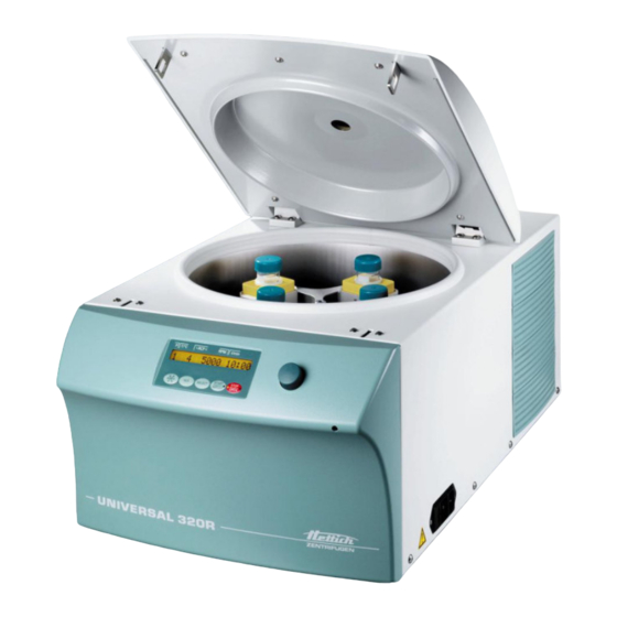
- Page 2 Fig. 1 >RCF< t/min START STOP SELECT IMPULS OPEN Fig. 2 UNIVERSAL 320 T/°C >RCF< t/min START STOP SELECT IMPULS OPEN Fig. 3 UNIVERSAL 320 R 2/146 Rev. 08 / 04.2020 AB1401DEENFRIT...
- Page 3 Herstellers / of the manufacturer / du fabricant / del costruttore Andreas Hettich GmbH & Co. KG • Föhrenstraße 12 • D-78532 Tuttlingen • Germany Hiermit erklären wir in alleiniger Verantwortung, dass das bezeichnete Gerät, inklusivem Gerätder Richtlinie über In- vitro-Diagnostika 98/79/EG entspricht.
- Page 4 The following additional European directives and ordinances have been applied: • Machinery Directive 2006/42/EU • EMC directive 2014/30/EU • Low voltage directive 2014/35/EU • RoHS II Directive 2011/65/EU (without involvement of a notified body) • Ordinance (EC) No. 1907/2006 (REACH) (without involvement of a notified body) Applied standards: According to the list of applied standards, which is part of the product file.
- Page 5 Für dieses Gerät gültige Normen und Vorschriften Das Gerät ist ein Produkt mit einem sehr hohen technischen Niveau. Es unterliegt umfangreichen Prüf- und Zertifizierungsverfahren gemäß folgenden Normen und Vorschriften in deren jeweils gültigen Fassung: Elektrische und mechanische Sicherheit für Konstruktion und Endprüfung: Normbaureihe: IEC 61010 (entspricht der Normenreihe DIN EN 61010) •...
- Page 6 Standards and regulations which apply to this device The device is a high-end technical product. It is subject to extensive testing and certification procedures according to the following standards and regulations in their respectively valid version: Electrical and mechanical safety for design and final testing: Standard series: IEC 61010 (conform to standards of DIN EN 61010) •...
- Page 7 Normes et règles en vigueur pour cet appareil Cet appareil est un produit avec un très haut niveau technique. Il est soumis à des vastes procédures de vérification et de certification, d'après les normes et prescriptions suivantes, dans leur version actuelle : Sécurité...
- Page 8 Norme e direttive valide per questo apparecchio L'apparecchio è un dispositivo di elevatissimo livello tecnico. È sottoposto a numerosi procedimenti di collaudo e certificazione, in conformità alle seguenti norme e direttive nella corrispondente versione di validità: Sicurezza elettrica e meccanica per la costruzione ed il collaudo finale: Serie di norma: IEC 61010 (corrisponde alla serie di norma DIN EN 61010) •...
- Page 9 +49 (0)7461 / 705-1125 info@hettichlab.com, service@hettichlab.com www.hettichlab.com © 2008 by Andreas Hettich GmbH & Co. KG All rights reserved. No part of this publication may be reproduced without the prior written permission of the copyright owner. Änderungen vorbehalten! , Modifications reserved! , Sous réserve de modifications ! , Con riserva di modifiche! AB1401DEENFRIT / Rev.
-
Page 10: Table Des Matières
Inhaltsverzeichnis Bestimmungsgemäße Verwendung ........................12 Restrisiken ................................12 Technische Daten ..............................12 Sicherheitshinweise .............................. 15 Transport und Lagerung ............................16 Transport ............................... 16 Lagerung ............................... 16 Bedeutung der Symbole ............................16 Lieferumfang ................................. 17 Auspacken der Zentrifuge ............................. 17 Inbetriebnahme ..............................18 Deckel öffnen und schließen .......................... - Page 11 Betriebsstunden-Abfrage ........................... 27 Kühlung (nur bei Zentrifuge mit Kühlung) ......................27 24.1 Standby-Kühlung............................27 24.2 Vorkühlen des Rotors ..........................27 Relative Zentrifugalbeschleunigung (RCF) ......................28 Zentrifugation von Stoffen oder Stoffgemischen mit einer höheren Dichte als 1,2 kg/dm ........ 28 Rotorerkennung ..............................28 Notentriegelung ..............................
-
Page 12: Bestimmungsgemäße Verwendung
Die Zentrifuge ist nur für diesen Verwendungszweck bestimmt. Eine andere oder darüber hinausgehende Benutzung gilt als nicht bestimmungsgemäß. Für hieraus entstehende Schäden haftet die Firma Andreas Hettich GmbH & Co. KG nicht. Zur bestimmungsgemäßen Verwendung gehört auch das Beachten aller Hinweise aus der Bedienungsanleitung und die Einhaltung der Inspektions- und Wartungsarbeiten. - Page 13 Andreas Hettich GmbH & Co. KG Hersteller D-78532 Tuttlingen Modell UNIVERSAL 320 R 1406-50 1406-51 1406-70 1406-71 Netzspannung (± 10%) 200-240 V 1∼ 100-127 V 1∼ 200-240 V 1∼ 100-127 V 1∼ Netzfrequenz 50 – 60 Hz 50 – 60 Hz 50 –...
- Page 14 Andreas Hettich GmbH & Co. KG Hersteller D-78532 Tuttlingen Modell UNIVERSAL 320 R 1406-20 1406-21 Netzspannung (± 10%) 200-240 V 1∼ 240 V 1∼ 115-127 V 1∼ Netzfrequenz 50 Hz 60 Hz 60 Hz Anschlusswert 800 VA 950VA Stromaufnahme 4.0 A 8.0 A...
-
Page 15: Sicherheitshinweise
Die Zentrifuge darf nicht mehr in Betrieb genommen werden, wenn der Schleuderraum sicherheitsrelevante Schäden aufweist. • Bei Ausschwingrotoren müssen die Tragzapfen regelmäßig gefettet werden (Hettich-Schmierfett Nr. 4051), um ein gleichmäßiges Ausschwingen der Gehänge zu gewährleisten. • Bei Zentrifugen ohne Temperaturregelung kann es bei erhöhter Raumtemperatur und/oder bei häufigem Gebrauch des Gerätes zur Erwärmung des Schleuderraums kommen. -
Page 16: Transport Und Lagerung
Gehängen und Zubehörteilen beeinträchtigen können, ist nicht erlaubt. • Reparaturen dürfen nur von einer vom Hersteller autorisierten Person ausgeführt werden. • Es dürfen nur Originalersatzteile und zugelassenes Originalzubehör der Firma Andreas Hettich GmbH & Co. KG verwendet werden. • Es gelten die folgenden Sicherheitsbestimmungen: EN / IEC 61010-1 und EN / IEC 61010-2-020 sowie deren nationalen Abweichungen. -
Page 17: Lieferumfang
Symbol am Gerät: Bedienungsanleitung beachten. Dieses Symbol verweist darauf hin, dass der Anwender die bereitgestellte Bedienungsanleitung beachten muss. Symbol in diesem Dokument: Achtung, allgemeine Gefahrenstelle. Dieses Symbol kennzeichnet sicherheitsrelevante Hinweise und deutet auf mögliche gefährliche Situationen hin. Das Nichtbeachten dieser Hinweise kann zu Sach- und Personenschäden führen. Symbol am Gerät und in diesem Dokument: Warnung vor Biogefährdung. -
Page 18: Inbetriebnahme
Inbetriebnahme • Die Transportsicherung am Gehäuseboden entfernen, siehe Hinweisblatt "Transportsicherung". • Die Zentrifuge an einem geeigneten Platz standsicher aufstellen und nivellieren. Bei der Aufstellung ist der geforderte Sicherheitsbereich gemäß EN / IEC 61010-2-020, von 300 mm um die Zentrifuge herum, einzuhalten. -
Page 19: Ein- Und Ausbau Des Rotors
Ein- und Ausbau des Rotors 11.1 Rotor mit Spannmutter Einbau des Rotors: Schmutzpartikel zwischen der Motorwelle und dem Rotor verhindern einen einwandfreien Sitz des Rotors und verursachen einen unruhigen Lauf. • Die Motorwelle (C) und die Bohrung des Rotors (A) reinigen und anschließend die Motorwelle leicht einfetten. -
Page 20: Gehänge In Den Rotor Einsetzen Und Herausnehmen
Gehänge in den Rotor einsetzen: • Den Rotor auf festen Sitz prüfen. • Die Tragzapfen (C) einfetten (Hettich-Schmierfett Nr 4051). • Die Gehänge (A) in den Rotor einsetzen. Dabei beachten, dass sich die Tragzapfen (C) in der Nuten (B) der Gehänge befinden. -
Page 21: Beladen Des Rotors
Beladen des Rotors Standard-Zentrifugiergefäße aus Glas sind belastbar bis RZB 4000 (DIN 58970 Teil 2). • Den Rotor auf festen Sitz prüfen. • Bei Ausschwingrotoren müssen alle Plätze des Rotors mit gleichen Gehängen besetzt sein. Bestimmte Gehänge sind mit der Nummer des Rotorplatzes gekennzeichnet. Diese Gehänge dürfen nur in den entsprechenden Platz des Rotors eingesetzt werden. -
Page 22: Handhabung Von Bio-Sicherheitssystemen
• Die vom Hersteller angegebene maximale Füllmenge der Zentrifugiergefäße darf nicht überschritten werden. Bei Winkelrotoren dürfen die Zentrifugierge- Flüssigkeit fäße nur soweit befüllt werden, dass während des Zentrifugationslaufes keine Flüssigkeit aus Gefäßen herausgeschleudert werden kann. Zentrifugalkraft • Beim Beladen der Winkelrotoren darf keine Flüssigkeit in die Winkelrotoren und in den Schleuderraum gelangen. •... -
Page 23: Deckel Mit Schraubverschluss
16.1.2 Deckel mit Schraubverschluss Deckel schließen: • Den Deckel auf das Gehänge aufsetzen. • Den Deckel von Hand, durch Drehen im Uhrzeigersinn, fest verschließen. Deckel öffnen: • Den Deckel von Hand solange entgegen dem Uhrzeigersinn drehen, bis sich der Deckel vom Gehänge abnehmen lässt. -
Page 24: Bedien- Und Anzeigeelemente
Bedien- und Anzeigeelemente Siehe Abbildung auf Seite 2. Fig. 2, Fig. 3: Anzeige- und Bedienfeld 17.1 Drehknopf Zum Einstellen der einzelnen Parameter. Drehen entgegen dem Uhrzeigersinn erniedrigt den Wert. Drehen im Uhrzeigersinn erhöht den Wert. 17.2 Tasten des Bedienfeldes • Wähltaste zum Anwählen der einzelnen Parameter. -
Page 25: Zentrifugations-Parameter Eingeben
T/°C Temperatur-Sollwert (nur bei Zentrifuge mit Kühlung). Einstellbar von -20°C bis +40°C, in 1°C-Schritten. Die tiefste erreichbare Temperatur ist rotorabhängig (siehe Kapitel "Anhang/Appendix, Rotoren und Zubehör/Rotors and accessories"). PROG STO Programmplatz auf dem das Programm gespeichert wird. Es können 9 Programme gespeichert werden (Programmplätze 1 - 2 - 3 - ... -
Page 26: Zentrifugation
Zentrifugation Während eines Zentrifugationslaufes dürfen sich gemäß EN / IEC 61010-2-020, in einem Sicherheitsbereich von 300 mm um die Zentrifuge herum, keine Personen, Gefahrstoffe und Gegenstände befinden. Wird der zulässige Gewichtsunterschied innerhalb der Beladung des Rotors überschritten, schaltet der Antrieb während des Anlaufs ab, und IMBALANCE wird angezeigt. -
Page 27: Akustisches Signal
Akustisches Signal Das akustische Signal ertönt: • bei Auftreten einer Störung im 2 s-Intervall. • nach Beendigung des Zentrifugationslaufes und Stillstand des Rotors im 30 s-Intervall. Durch Öffnen des Deckels oder Drücken einer beliebigen Taste wird das akustische Signal beendet. Das Signal nach Beendigung des Zentrifugationslaufes kann, bei Stillstand des Rotors, folgendermaßen aktiviert oder deaktiviert werden: •... -
Page 28: Relative Zentrifugalbeschleunigung (Rcf)
Relative Zentrifugalbeschleunigung (RCF) Die relative Zentrifugalbeschleunigung (RCF) wird als Vielfaches der Erdbeschleunigung (g) angegeben. Sie ist ein einheitsfreier Zahlenwert und dient zum Vergleich der Trenn- und Sedimentationsleistung. Die Berechnung erfolgt nach der Formel: × × ⇒ ×... -
Page 29: Notentriegelung
Notentriegelung Bei einem Stromausfall kann der Deckel nicht motorisch entriegelt werden. Es muss eine Notentriegelung von Hand durchgeführt werden. Zur Notentriegelung die Zentrifuge vom Netz trennen. Den Deckel nur bei Stillstand des Rotors öffnen. Siehe Abbildung auf Seite 2. • Den Netzschalter ausschalten (Schalterstellung "0"). -
Page 30: Zentrifuge (Gehäuse, Deckel Und Schleuderraum)
29.1 Zentrifuge (Gehäuse, Deckel und Schleuderraum) 29.1.1 Oberflächenreinigung und -pflege • Das Gehäuse der Zentrifuge und den Schleuderraum regelmäßig säubern und bei Bedarf mit Seife oder einem milden Reinigungsmittel und einem feuchten Tuch reinigen. Dies dient zum einen der Hygiene und es verhindert Korrosion durch anhaftende Verunreinigungen. -
Page 31: Rotoren Und Zubehör
29.2 Rotoren und Zubehör 29.2.1 Reinigung und Pflege • Um einer Korrosion und Materialveränderungen vorzubeugen müssen die Rotoren und das Zubehör regelmäßig mit Seife oder einem milden Reinigungsmittel und einem feuchten Tuch gereinigt werden. Die Reinigung wird mindestens einmal wöchentlich empfohlen. Verschmutzungen müssen sofort entfernt werden. •... -
Page 32: Entfernen Radioaktiver Verunreinigungen
Die Rotoren und das Zubehör müssen unmittelbar nach dem Entfernen der radioaktiven Verunreinigungen getrocknet werden. 29.2.4 Tragzapfen Bei Ausschwingrotoren müssen die Tragzapfen regelmäßig gefettet werden (Hettich-Schmierfett Nr. 4051), um ein gleichmäßiges Ausschwingen der Gehänge zu gewährleisten. 29.2.5 Rotoren und Zubehör mit begrenzter Verwendungsdauer Die Verwendung von bestimmten Rotoren, Gehängen und Zubehörteilen ist zeitlich begrenzt. -
Page 33: Störungen
Störungen Lässt sich der Fehler laut Störungstabelle nicht beheben, so ist der Kundendienst zu benachrichtigen. Bitte den Zentrifugentyp und die Seriennummer angeben. Beide Nummern sind auf dem Typenschild der Zentrifuge ersichtlich. Einen NETZ-RESET durchführen: − Den Netzschalter ausschalten (Schalterstellung "0"). −... -
Page 34: Rücksendung Von Geräten
Vor der Rücksendung des Gerätes muss die Transportsicherung eingebaut werden. Wird das Gerät oder dessen Zubehör an die Firma Andreas Hettich GmbH & Co. KG zurückgesandt, so muss dieses, zum Schutz von Personen, Umwelt und Material, vor dem Versand dekontaminiert und gereinigt werden. - Page 35 Contents Use according to specification ..........................37 Remaining risks ..............................37 Technical specifications ............................37 Notes on safety ..............................40 Transport and storage............................41 Transport ............................... 41 Storage ................................41 Symbol meanings ..............................41 Delivery checklist ..............................42 Unpacking the centrifuge ............................42 Initial operation ..............................
- Page 36 Recall hours of operation ..........................51 Cooling (only in centrifuges with cooling) ......................52 24.1 Standby-cooling ............................52 24.2 Pre-cooling the rotor ..........................52 Relative centrifugal force (RCF) ........................52 Centrifugation of materials or mixtures of materials with a density higher than 1.2 kg/dm .......
-
Page 37: Use According To Specification
In particular, these include samples for preparation of in-vitro diagnostic purposes in human medicine. The centrifuge is only meant for this purpose. Another use or one which goes beyond this, is considered to be non-intended. The company Andreas Hettich GmbH & Co. KG is not liable for damage resulting from this. - Page 38 Andreas Hettich GmbH & Co. KG Manufacturer D-78532 Tuttlingen Model UNIVERSAL 320 R Type 1406-50 1406-51 1406-70 1406-71 100-127 V 1 ∼ 100-127 V 1 ∼ 1 ∼ 1 ∼ Mains voltage (± 10%) 200-240 V 200-240 V Mains frequency 50 –...
- Page 39 Andreas Hettich GmbH & Co. KG Manufacturer D-78532 Tuttlingen Model UNIVERSAL 320 R Type 1406-20 1406-21 200-240 V 1 ∼ 240 V 1 ∼ 115-127 V 1 ∼ Mains voltage (± 10%) Mains frequency 50 Hz 60 Hz 60 Hz...
-
Page 40: Notes On Safety
The centrifuge may no longer be put into operation when the centrifuging chamber has safety- related damages. • With swing-out rotors the trunnions must be regularly lubricated (Hettich Lubricating Grease No. 4051) in order to ensure consistent swinging out of the hangers. •... -
Page 41: Transport And Storage
• Repairs must only be carried out by personnel authorised to do so by the manufacturer. • Only original spare parts and original accessories licensed by the Andreas Hettich GmbH & Co. KG company are allowed to be utilised. •... -
Page 42: Delivery Checklist
Symbol in this document: Attention, general hazard area. This symbol refers to safety relevant warnings and indicates possibly dangerous situations. The non-adherence to these warnings can lead to material damage and injury to personal. Symbol on the device and in this document: Beware of biohazard. -
Page 43: Initial Operation
Initial operation • Remove the transportation safety device from the bottom of the housing, see sheet ”Transportation safety device" • Position the centrifuge in a stable and level manner in a suitable place. During set-up, the required safety margin of 300 mm around the centrifuge is to be kept according to EN / IEC 61010-2-020. When the centrifuge is running, according to EN / IEC 61010-2-020, no persons, dangerous substances or objects may be within the safety margin of 300 mm around the centrifuge. -
Page 44: Installation And Removal Of The Rotor
Installation and removal of the rotor 11.1 Rotor with clamping nut Rotor installation: Dirt particles between the motor shaft and rotor prevent the rotor from having a perfect seat and cause it to run unsteadily. • Clean the motor shaft (C) and the bore of the rotor (A) and then apply a thin coat of grease to the motor shaft. -
Page 45: Inserting And Removing Hangers Into/From The Rotor
• Check the rotor to make sure it is seated firmly. • Grease the lifting lug (C) (Hettich lubricating grease, no. 4051). • Insert hangers (A) into the rotor. While doing so, make sure that the lifting lugs (C) are in the grooves (B) of the hangers. -
Page 46: Loading The Rotor
Loading the rotor Standard centrifuge containers of glass will not stand RCF values exceeding 4000 (DIN 58970, pg. 2). • Check the rotor for firm seating. • With swing-out rotors all rotor positions must be lined with identical hangers. Certain hangers are marked with the number of the rotor position. -
Page 47: Handling Of Bio-Safety Systems
• The maximum filling quantity for the centrifuge containers specified by the manufacturer must not be exceeded. In the case of angle rotors, the centrifuging Fluid vessels may only be filled so far that no fluid can be expelled from them while the centrifuge is running. -
Page 48: Lid With Screw Closure
16.1.2 Lid with screw closure Closing the lid: • Place the lid on the hanger. • Tightly seal the lid by hand by turning it clockwise. Opening the lid: • Turn the lid by hand counterclockwise until the lid can be removed from the hanger. 16.1.3 Lid with clamp and tension lock open... -
Page 49: Control Knob
17.1 Control knob For setting the individual parameters. Turning anticlockwise reduces the value. Turning clockwise increases the value. Control panel pushbuttons (keys) • Selection control key for selection of specific parameter. SELECT The subsequent parameter is selected by every further keystroke. •... -
Page 50: Entering Centrifugation Parameter
Entering centrifugation parameter If no key is pressed for 8 seconds long after the selection or during the input of parameters, the previous values will be shown in the display. The input of parameter then has to be executed again. •... -
Page 51: Centrifugation With Pre-Set Time
Centrifugation with pre-set time • Adjusting time or recall a programme with pre-set time (see Chapter "Programming"). • Press the key . The LED in the button lights up for as long as the rotor turns. START / IMPULS START / IMPULS •... -
Page 52: Cooling (Only In Centrifuges With Cooling)
Cooling (only in centrifuges with cooling) The temperature set-point can be adjusted from -20°C to +40°C. The lowest obtainable temperature is dependent on the rotor (see Chapter "Anhang/Appendix, Rotoren und Zubehör/Rotors and accessories"). 24.1 Standby-cooling With rotor standstill and closed lid the centrifugal chamber is cooled to the pre-selected temperature. The temperature set-point is shown in the display. -
Page 53: Rotor Recognition
Centrifugation of materials or mixtures of materials with a density higher than 1.2 kg/dm When centrifuging with maxim revolutions per minute the density of the materials or the material mixtures may not exceed 1.2 kg/dm The speed must be reduced for materials or mixtures of materials with a higher density. The permissible speed can be calculated using the following formula: Reduced speed... -
Page 54: Maintenance And Servicing
Maintenance and servicing The device can be contaminated. Pull the mains plug before cleaning. Before any other cleaning or decontamination process other than that recommended by the manufacturer is applied, the user has to check with the manufacturer that the planned process does not damage the device. •... -
Page 55: Rotors And Attachments
29.2 Rotors and Attachments 29.2.1 Cleaning and care • In order to avoid corrosion and changes in materials, the rotors and accessories have to be cleaned regularly with soap or with a mild cleaning agent and a moist cloth. Cleaning is recommended at least once a week. Contaminants must be removed immediately. -
Page 56: Trunnions
29.2.4 Trunnions With swing-out rotors the trunnions must be regularly lubricated (Hettich Lubricating Grease No. 4051) in order to ensure consistent swinging out of the hangers. 29.2.5 Rotors and accessories with limited service lives The use of certain rotors, hangers and accessory parts is limited by time. -
Page 57: Faults
Faults If the fault cannot be eliminated with the help of the fault table, please inform Customer Service. Please specify the type of centrifuge and the serial number. Both numbers can be found on the name plate of the centrifuge. Perform a MAINS RESET: −... -
Page 58: Returning Devices
Before returning the device, a transport securing device has to be installed. If the device or its accessories are returned to Andreas Hettich GmbH & Co. KG, in order to provide protection for people, the environment and materials, it has to be decontaminated and cleaned before being shipped. - Page 59 Table des matières Usage conforme ..............................61 Risques résiduels ..............................61 Données techniques ............................. 61 Consignes de sécurité ............................64 Transport et stockage ............................65 Transport ............................... 65 Stockage ................................ 65 Signification des symboles ............................ 65 Composition de la livraison ........................... 66 Déballer la centrifugeuse ............................
- Page 60 Interrogation du compteur de durée de fonctionnement ..................77 Refroidissement (uniquement sur centrifugeuse avec refroidissement) ............77 24.1 Refroidissement en veilleuse ........................77 24.2 Pré-refroidissement du rotor ........................77 Accélération centrifuge relative (RCF) ......................78 Centrifugation de matières et de mélanges d'une densité supérieure à 1,2 kg/dm ..........
-
Page 61: Usage Conforme
Toute utilisation en dehors ou au delà de ce cadre est considérée comme non conforme. L'entreprise Andreas Hettich GmbH & Co. KG décline toute responsabilité pour tout dommage en résultant. L'utilisation conforme comprend également le respect de toutes les indications contenues dans le mode d'emploi et des travaux d'inspection et d'entretien. - Page 62 Andreas Hettich GmbH & Co. KG Fabricant D-78532 Tuttlingen Modèle UNIVERSAL 320 R Type 1406-50 1406-51 1406-70 1406-71 Tension du réseau ( ± 10%) 100-127 V 1 ∼ 100-127 V 1 ∼ 1 ∼ 1 ∼ 200-240 V 200-240 V Fréquence du réseau...
- Page 63 Andreas Hettich GmbH & Co. KG Fabricant D-78532 Tuttlingen Modèle UNIVERSAL 320 R Type 1406-20 1406-21 Tension du réseau ( ± 10%) 200-240 V 1 ∼ 240 V 1 ∼ 115-127 V 1 ∼ Fréquence du réseau 50 Hz 60 Hz...
-
Page 64: Consignes De Sécurité
à la sécurité. • Les goupilles de fixation des rotors à amortissement doivent être graissées régulièrement (graisse de lubrification Hettich n° 4051) de manière à assurer le balancement régulier de la suspension. • Concernant les centrifugeuses sans réglage de température, il peut y avoir un réchauffement dans la cuve de centrifugeuse en cas de température ambiante élevée et/ou d'utilisation fréquente de... -
Page 65: Transport Et Stockage
Les réparations ne peuvent être effectuées que par une personne autorisée à cet effet par le fabricant. • Utiliser uniquement les pièces de rechange originales et les accessoires d'origine homologués par les Etablissements Andreas Hettich GmbH & Co. KG. • Les dispositions de sécurité suivantes font foi : EN / IEC 61010-1 et EN / IEC 61010-2-020 ainsi que les dérogations nationales. -
Page 66: Composition De La Livraison
Symbole sur l'appareil : respecter le mode d'emploi. Ce symbole indique que l'utilisateur doit respecter le mode d'emploi mis à disposition. Symbole dans ce document: Attention, zone de danger général. Ce symbole indique des consignes de sécurité et signale des situations pouvant être sources de danger. Le non-respect de ces instructions peut entraîner des dégâts matériels et personnels. -
Page 67: Mise En Service
Mise en service • Retirer du fond du carter les dispositifs de sécurité pour le transport, voir pour cela la fiche de données "Dispositifs de sécurité pour le transport". • Placer la centrifugeuse sur un emplacement approprié de manière à ce qu'elle soit stable et mettre de niveau. Lors de la mise en place, il faut respecter la zone de sécurité... -
Page 68: Montage Et Démontage Du Rotor
Montage et démontage du rotor 11.1 Rotor avec écrou Montage du rotor : La présence d'impuretés entre l'arbre moteur et le rotor empêche au rotor d'avoir une position parfaite, et provoque un fonctionnement irrégulier du rotor. • Nettoyer l'arbre moteur (C) et l'ouverture du rotor (A), graisser ensuite légèrement l'arbre moteur. -
Page 69: Insérer Et Retirer Les Suspensions Dans Le Rotor
• Vérifier si le rotor se trouve dans une position fixe. • Graisser les tourillons (C) (graisse Hettich n° 4051). • Insérer les suspensions (A) dans le rotor. Pour ce faire, veiller à ce que les tourillons (C) se trouvent dans les rainures (B) des suspensions. -
Page 70: Chargement Du Rotor
Chargement du rotor Des récipients standard de centrifugation en verre sont résistants jusqu' à un ACR de 4000 (DIN 58970, partie 2). • Vérifier la stabilité d'assise du rotor. • Dans le cas des rotors à balanciers, toutes les positions des rotors doivent être équipées avec les mêmes balanciers. -
Page 71: Manipuler Des Systèmes De Biosécurité
• La quantité maximale de remplissage indiquée par le fabricant pour les récipients de centrifugation ne doit pas être dépassée. Pour rotors angulaires, remplir Liquide réservoirs de centrifugation de sorte que du liquide ne puisse pas être projeté à l'extérieur pendant le cycle de centrifugation Force centrifuge •... -
Page 72: Couvercle Avec Fermeture À Vis
16.1.2 Couvercle avec fermeture à vis Fermer le couvercle : • Placer le couvercle sur le balancier. • Bien fermer le couvercle en le tournant à la main dans le sens des aiguilles d'une montre. Ouvrir le couvercle : • Tourner le couvercle à... -
Page 73: Stockage De Systèmes De Biosécurité
16.2 Stockage de systèmes de biosécurité • Entreposer les systèmes de biosécurité uniquement avec le couvercle ouvert afin d'éviter une détérioration des bagues d'étanchéité durant le stockage. Organes de commande et indicateurs Voir illustration sur la page 2. Fig. 2, Fig. 3: Console des indicateurs et organes de commande 17.1 Bouton de réglage... -
Page 74: Possibilités De Réglage
17.3 Possibilités de réglage PROG RCL Position de programme du programme appelé. t/min Durée de fonctionnement. Réglable de 0 à 99 min, par pas de 1 min. t/sec Durée de fonctionnement. Réglable de 0 à 59 s, par pas de 1 seconde. Fonctionnement continu "... -
Page 75: Saisie Des Paramètres De Centrifugation
Saisie des paramètres de centrifugation Après sélection de paramètres et pendant la sélection des paramètres, l'indicateur bascule sur les valeurs précédentes si aucune action n'exécutée sur les touches pendant 8 secondes. Il est alors nécessaire de recommencer la saisie des paramètres. •... -
Page 76: Centrifugation
Centrifugation Durant un processus de centrifugation, aucune personne, matière dangereuse et aucun objet ne doivent se trouver dans une zone de sécurité de 300 mm autour de la centrifugeuse selon EN / IEC 61010-2-020. L'entraînement est stoppé en phase de montée en puissance si la différence de tare admissible a été dépassée pendant le chargement du rotor, l'indicateur de déséquilibre s'allume et la mention IMBALANCE est affichée. -
Page 77: Signal Sonore
Signal sonore Le signal sonore retentit : • en présence d'un défaut à un intervalle de 2 s. • au terme de la centrifugation et après immobilisation du rotor, à un intervalle de 30 s. Le signal sonore cesse après ouverture du couvercle, en appuyant sur une touche quelconque. Pour activer / désactiver le signal sonore après la centrifugation, alors que le rotor est immobilisé, procéder comme suit : •... -
Page 78: Accélération Centrifuge Relative (Rcf)
Accélération centrifuge relative (RCF) L'accélération centrifuge relative (RCF) est indiqué en tant que multiple de l'accélération gravitationnelle (g). Il s'agit d'une valeur dépourvue d'unité, qui sert à la comparaison entre la puissance de séparation et de sédimentation. Le calcul s’effectue à l’aide de la formule suivante: ... -
Page 79: Déverrouillage D'urgence
Déverrouillage d'urgence En cas de panne de courant, le couvercle ne peut pas être déverrouillé avec le moteur. Il est nécessaire d'exécuter un déverrouillage manuel. Avant d'exécuter le déverrouillage manuel, retirer la fiche de l'alimentation. Attendre que le rotor est à l'arrêt pour ouvrir le couvercle. Voir illustration sur la page 2. -
Page 80: Décontamination De Substances Radioactives
29.1.3 Décontamination de substances radioactives • L'agent employé doit expressément convenir pour une décontamination de substances radioactives. • Substances des agents adaptés à une décontamination des substances radioactives : agents anioniques, non ioniques agents, éthanol polyhydre. • Après décontamination des substances radioactives, enlevez les résidus en essuyant l'appareil avec un chiffon humide. -
Page 81: Désinfection
29.2.4 Goupilles de fixation Les goupilles de fixation des rotors à amortissement doivent être graissées régulièrement (graisse de lubrification Hettich n° 4051) de manière à assurer le balancement régulier de la suspension. 29.2.5 Rotors et accessoires à durée d'utilisation limitée L'utilisation de certains rotors, balanciers et accessoires est limitée dans le temps. -
Page 82: Autoclave
29.3 Autoclave Vous pouvez stériliser par autoclave à 121°C / 250°F (20 min) les accessoires suivants : • rotors à oscillation • rotors angulaires en aluminium • balancier en métal • couvercle avec bio-étanchéité • adaptateur Nous ne pouvons faire aucune déclaration sur le degré de stérilisation. Avant autoclave, retirez les couvercles des rotors et réservoirs. -
Page 83: Défauts
Défauts Si l'erreur ne peut pas être éliminée d'après le tableau des défauts, il faut alors avertir le service après-vente. Veuillez indiquer le type de centrifuge et le numéro de série. Les deux numéros sont indiqués sur la plaque signalétique de la centrifugeuse. Effectuer une RÉINITIALISATION DU SECTEUR : −... -
Page 84: Renvoi D'appareils Au Fabricant
Avant de renvoyer l'appareil, il faut monter le dispositif de fixation pour le transport. Dans le cas où l'appareil ou ses accessoires doivent être retournés à la société Andreas Hettich GmbH & Co. KG, il faut les décontaminer et les nettoyer avant expédition, dans le but d'assurer la protection des personnes, de l'environnement et du matériel. - Page 85 Indice Uso previsto ................................87 Rischi residui ................................ 87 Dati tecnic ................................88 Indicazioni inerenti la sicurezza ..........................91 Trasporto ed immagazzinaggio ..........................92 Trasporto ............................... 92 Immagazzinaggio ............................92 Significato dei simboli ............................92 Contenuto della fornitura ............................93 Disimballo della centrifuga ............................
- Page 86 Consultazione delle ore di funzionamento....................... 103 Raffreddamento (solo per centrifuga con raffreddamento) ................103 24.1 Raffreddamento-Standby ......................... 103 24.2 Pre-raffreddamento del rotore ........................103 Accelerazione centrifuga relativa (RCF) ......................104 Centrifugazione di sostanze o di miscele di sostanze con densità maggiore di 1,2 kg/dm ......
-
Page 87: Uso Previsto
Le centrifuga è destinata solo a questo scopo d'impiego. Un diverso od ulteriore tipo di impiego non è regolamentare. La ditta Andreas Hettich GmbH & Co. KG non si prende carico di alcuna responsabilità nel caso di danni da ciò derivanti. -
Page 88: Dati Tecnic
Dati tecnic Andreas Hettich GmbH & Co. KG Costruttore D-78532 Tuttlingen Modello UNIVERSAL 320 UNIVERSAL 320 R Tipo 1401 1401-01 1406 1406-01 115-127 V 1 ∼ Tensione di rete ( ± 10%) 200-240 V 1 ∼ 100-127 V 1 ∼ 200-240 V 1 ∼... - Page 89 Andreas Hettich GmbH & Co. KG Costruttore D-78532 Tuttlingen Modello UNIVERSAL 320 R Tipo 1406-50 1406-51 1406-70 1406-71 Tensione di rete ( ± 10%) 1 ∼ 100-127 V 1 ∼ 1 ∼ 100-127 V 1 ∼ 200-240 V 200-240 V Frequenza di rete 50 –...
- Page 90 Andreas Hettich GmbH & Co. KG Costruttore D-78532 Tuttlingen Modello UNIVERSAL 320 R Tipo 1406-20 1406-21 Tensione di rete ( ± 10%) 200-240 V 1 ∼ 240 V 1 ∼ 115-127 V 1 ∼ Frequenza di rete 50 Hz 60 Hz...
-
Page 91: Indicazioni Inerenti La Sicurezza
• In rotori oscillanti, i perni di trascinamento devono essere lubrificati regolarmente (Grasso lubrificante Hettich no. d’ord. 4051) per consentire un’oscillazione equilibrata dei ganci. • Nel caso di centrifughe senza regolazione termica, con temperature ambiente elevate e/o con frequente impiego dell'apparecchiatura può... -
Page 92: Trasporto Ed Immagazzinaggio
Gli interventi di riparazione devono essere effettuati esclusivamente da una persona autorizzata dal costruttore. • Devono essere impiegati solo ed esclusivamente pezzi di ricambio originali ed accessori autorizzati della ditta Andreas Hettich GmbH & Co. KG. • Sono di validità le seguenti norme di sicurezza: EN / IEC 61010-1 e EN / IEC 61010-2-020 come anche le loro nazionali varianti. -
Page 93: Contenuto Della Fornitura
Simbolo sull'apparecchiatura: Prestare attenzione alle istruzioni per l'uso. Questo simbolo indica che l'utente deve prestare attenzione alle istruzioni per l'uso fornite. Simbolo in questo documento. Attenzione, punto pericoloso generico. Questo simbolo contraddistingue le avvertenze relative alla sicurezza e indica situazioni potenzialmente pericolose . -
Page 94: Messa In Funzione
Messa in funzione • Togliere la sicura per il trasporto, che si trova sul fondo dell’alloggiamento, vedere foglio avvisi "Sicura per il trasporto". • Porre la centrifuga in un posto adatto e livellarla. Per l’installazione deve essere rispettata la zona di sicurezza di 300 mm attorno alla centrifuga, richiesta in conformità... -
Page 95: Montaggio E Smontaggio Del Rotore
Montaggio e smontaggio del rotore 11.1 Rotore con dado di bloccaggio Montaggio del rotore: Le particelle di sporco tra l'albero motore ed il rotore impediscono un perfetto posizionamento in sede del rotore e sono causa di un irrequieto movimento. • Pulire l'albero motore (C) ed il foro del rotore (A) ed ingrassare poi leggermente l'albero motore. -
Page 96: Applicare Ed Estrarre I Ganci Dal Rotore
Applicare i ganci nel rotore: • Controllare che il rotore sia fissato stabilmente. • Ingrassare i perni di supporto (C) (grasso lubrificante Hettich N° 4051). • Applicare i ganci (A) nel rotore. A questo riguardo prestare attenzione che i perni di supporto (C) si trovino nelle scanalature (B) dei ganci. -
Page 97: Carico Del Rotore
Carico del rotore Lo standard dei recipienti di vetro centrifugati sono da caricare fino a RCF 4000 (DIN 58970 capoverso 2). • Verificare che il rotore sia fissato. • Nel caso di rotori oscillanti, tutti i siti del rotore devono essere muniti di ganci uguali . Particolari ganci sono contrassegnati con il numero del sito del rotore. -
Page 98: Impiego Dei Sistemi Di Biosicurezza
• Nel caso di contenitori con inserimenti in gomma, deve essere sempre mantenuto lo stesso numero di inserimenti in gomma sotto i contenitori di centrifugazione. • L'operazione di riempimento dei contenitori di centrifugazione è ammessa solo al di fuori della centrifuga. •... -
Page 99: Coperchio Con Staffa E Chiusura In Bloccaggio A Leva
• Girare a mano il coperchio in senso antiorario, fino a quando il coperchio si lascia togliere dal gancio. 16.1.3 Coperchio con staffa e chiusura in bloccaggio a leva open close Chiudere il coperchio: • Girare la staffa nella posizione " ↓ open ↓ " (a). Le frecce della dicitura ↓ open ↓ " devono indicare verso il basso, in modo che il testo "open"... -
Page 100: Elementi Di Operazione E Visualizzazione
Elementi di operazione e visualizzazione Vedere illustrazione alla pagina 2 Fig. 2, Fig. 3: Display 17.1 Manopola Per l'impostazione dei singoli parametri. La rotazione in senso antiorario riduce il valore. La rotazione in senso orario aumenta il valore. 17.2 Tasti del display •... -
Page 101: Inserire I Parametri Di Centrifugazione
Livelli di inizio 1 - 9. Livello 9 = tempo di avvio più breve, livello 1 = tempo di avvio più lungo Livelli di frenatura 0 - 9. Livello 9 = tempo di arresto più breve, livello 1 = tempo di arresto più lungo Livello 0 = tempo di arresto più... -
Page 102: Centrifugazione
Centrifugazione Durante un’operazione di centrifugazione, in una zona di sicurezza di 300 mm attorno alla centrifuga non deve sostare alcuna persona, materiali pericolosi ed oggetti, in conformità alle norme EN / IEC 61010-2-020. Nel caso in cui la differenza di peso permissibile nel caricamento del rotore venga superata, si ferma l’azionamento durante l‘avvio, si illumina l‘indicazione di squilibrio e compare la dicitura IMBALANCE. -
Page 103: Segnale Acustico
Segnale acustico Il segnale acustico si attiva quando: • con il verificarsi di un guasto con intervallo di 2 sec • dopo il terminare della corsa di centrifugazione e arresto del rotore con intervallo di 30 secondi Aprendo il coperchio oppure premendo un tasto qualsiasi, il segnale acustico cessa. Il segnale che si attiva in seguito alla cessazione della corsa di centrifugazione, può... -
Page 104: Accelerazione Centrifuga Relativa (Rcf)
Accelerazione centrifuga relativa (RCF) L’accelerazione centrifuga relativa (RCF) è indicata come un multiplo dell’accelerazione terrestre (g). È un valore numerico privo di unità e funge per paragonare le prestazioni di separazione de sedimentazione. Il calcolo viene eseguito in base alla formula: ... -
Page 105: Sblocco Di Emergenza
Sblocco di emergenza In caso di una caduta di tensione, il coperchio non può essere sbloccato a motore. Deve essere effettuata manualmente uno sblocco di emergenza. Per lo sblocco di emergenza, disconnettere la centrifuga dalla rete elettrica. Aprire il coperchio solo con l’arresto del rotore. Vedere illustrazione alla pagina 2. -
Page 106: Rimuovere Contaminazioni Radioattive
29.1.3 Rimuovere contaminazioni radioattive • La sostanza deve essere certificata in modo speciale per rimuovere contaminazioni radioattive. • Ingredienti di sostanze adatte alla rimozione di contaminazioni radioattive: tensidi anionici, tensidi non ionici, etanolo poliidrato. • Dopo aver rimosso le contaminazioni radioattive, rimuovere i resti della sostanza pulendo di nuovo con un panno umido. -
Page 107: Disinfezione
I rotori e gli accessori devono essere asciugati subito dopo la rimozione delle contaminazioni radioattive. 29.2.4 Perni di trascinamento In rotori oscillanti, i perni di trascinamento devono essere lubrificati regolarmente (Grasso lubrificante Hettich no. d’ord. 4051) per consentire un’oscillazione equilibrata dei ganci. 29.2.5 Rotori ed accessori con limitata durata di impiego L'impiego di particolari rotori, ganci ed elementi accessori è... -
Page 108: Trattamento In Autoclave
29.3 Trattamento in autoclave I seguenti accessori possono essere trattati in autoclave a 121°C / 250°F (20 min). • Rotori di smorzamento • Rotori a squadra in alluminio • Gancio in metallo • Coperchio con ermetizzazione biologica • Adattatore Per quanto riguarda il grado di sterilizzazione non può essere citato alcun dato. I coperchi dei rotori ed i serbatoi devono venir tolti prima del trattamento in autoclave. -
Page 109: Guasti
Guasti Se non si riesce a eliminare l’errore seguendo le indicazioni della tabella guasti, informare il servizio assistenza clienti. Si prega di indicare il tipo di centrifuga e il numero di serie. Entrambi i numeri sono visibili sulla targhetta di modello della centrifuga. -
Page 110: Rispedizione Di Apparecchi
Prima di rispedire un apparecchio deve essere montata la protezione per il trasporto. Se l'apparecchio o uno dei suoi accessori viene rispedito alla ditta Andreas Hettich GmbH & Co. KG, esso deve essere prima decontaminato e pulito per la tutela di persone, ambiente e materiale. -
Page 111: Anhang / Appen
Anhang / Appen 33.1 Rotoren und Zubehör / Rotors and accessories 1324 1490 1492 Ausschwingrotor 4-fach / Swing out rotor 4-times mit Bioabdichtung / with bio-containment 1329 1330 1331 0765 0534 0535 0500 0519 0521 0507 0518 90° Kapazität / capacity 9 - 10 Maße / dimensions ∅... - Page 112 1324 1490 1492 Ausschwingrotor 4-fach / Swing out rotor 4-times mit Bioabdichtung / with bio-containment 1339 1343 1347 1348 0509 Rhesus 90° 4 – 4,5 4 - 7 Kapazität / capacity Maße / dimensions ∅ x L 6 x 45 10 x 60 10 x 88 17 x 120...
- Page 113 1324 1490 1492 Ausschwingrotor 4-fach / Swing out rotor 4-times mit Bioabdichtung / with bio-containment 1383 1384 1396 1457 0513 0547 90° 2,6 – 2,9 4,5 - 5 1,6 -5 4 –7 1,1 – 1,4 Kapazität / capacity Maße / dimensions ∅ x L 13 x 65 13 x 90 11 x 92...
- Page 114 1324 1398 Ausschwingrotor 4-fach / Swing out rotor 4-times 1482A + 2 x 0716 1482A (2 x) 0500 90° 2,6 –3,4 4 – 4,5 9 – 10 4 - 7 8,5 – 10 Kapazität / capacity Maße / dimensions ∅ x L 13 x 65 15 x 75 16 x 92...
- Page 115 1494 1427 1421 Ausschwingrotor 4-fach / Swing out rotor 4-times 1357 5229 5230 5230 5231 5231 1326 5229 Rhe- 0578 0507 0518 0501 90° 4,5 – 5 2,7 - 3 4,5 – 5 8,5 - 10 Kapazität / capacity 12 x 12 x Maße / dimensions ∅...
- Page 116 1494 1427 1421 Ausschwingrotor 4-fach / Swing out rotor 4-times 5279 5278 1327 5233 5271 5232 5275 0521 0519 0509 90° 7,5 – 8,2 1,1 – 1,4 9 - 10 4 - 7 Kapazität / capacity Maße / dimensions ∅ x L 15 x 92 8 x 66 10 x 60...
- Page 117 1494 1425 Ausschwingrotor 4-fach / Swing out rotor 4-times 1431 1436 1437 1458 1435 1439 0500 0521 0526 0519 0507 0518 90° 7,5 - 8,2 1,1 – 1,4 9 – 10 Kapazität / capacity Maße / dimensions ∅ x L 14 x 100 17 x 100 15 x 92...
- Page 118 1494 1425 Ausschwingrotor 4-fach / Swing out rotor 4-times 1441 1443 1444 1737 0513 2078 0536 90° 4 – 5,5 7,5 – 8,5 4 – 7 8,5 – 10 Kapazität / capacity Maße / dimensions ∅ x L 15 x 75 15 x 92 16 x 75 16 x 100...
- Page 119 1494 1495 1492 Ausschwingrotor 4-fach / Swing out rotor 4-times mit Bioabdichtung / with bio-containment 1339 1343 1329 1330 1459 Rhe- 0500 0519 0507 0518 90° 9 - 10 4 - 5,5 7,5 - 8,2 Kapazität / capacity 10 x 10 x Maße / dimensions ∅...
- Page 120 1494 1495 1492 Ausschwingrotor 4-fach / Swing out rotor 4-times mit Bioabdichtung / with bio-containment 1383 0501 0578 90° 2,6 – 2,9 2,7 – 3 4,5 - 5 Kapazität / capacity Maße / dimensions ∅ x L 13 x 65 11 x 66 13 x 90 11 x 92...
- Page 121 1554 1560 1561 1565 Ausschwingrotor 4-fach / Swing out rotor 4-times mit Bioabdichtung / with bio-containment ----- max. Laufzyklen / max. cycles: 80000 max. Beladung / max. load: 290 g 1571 1593 1589 1588 2078 0536 ---- 0553 0501 0578 0500 0507 0518...
- Page 122 1554 1560 1561 1565 Ausschwingrotor 4-fach / Swing out rotor 4-times mit Bioabdichtung / with bio-containment ---- max. Laufzyklen / max. cycles: 80000 max. Beladung / max. load: 290 g 1589 1588 ---- ---- ---- ---- ---- ---- ---- ---- 90°...
- Page 123 1554 1560 1561 1565 Ausschwingrotor 4-fach / Swing out rotor 4-times mit Bioabdichtung / with bio-containment ---- max. Laufzyklen / max. cycles: 80000 max. Beladung / max. load: 290 g 1578 1579 1581 1582 1583 1584 1585 0513 0545 90° max.
- Page 124 1554 1559 Ausschwingrotor 4-fach / Swing out rotor 4-times max. Laufzyklen / max. cycles: 80000 max. Beladung / max. load: 200 g 1486 1482A 1482A + 4 x 0715 1486 1482A (4x) 0553 0501 0578 0500 0507 0518 90° max. Laufzyklen / max.
- Page 125 1554 1563 Ausschwingrotor 4-fach / Swing out rotor 4-times max. Laufzyklen / max. cycles: 80000 max. Beladung / max. load: 160 1592 1592 + E2109 E2110-A 90° 0509 0513 max. Laufzyklen / max. cycles 100 000 Kapazität / capacity Maße / dimensions ∅ x L 17 x 100 17 x 120 29 x 115...
- Page 126 1624 1308 1345 1346 1366 Ausschwingrotor 4-fach / Swing out rotor 4-times 1326 1357 5277 Rhe- 0521 2078 0536 90° Kapazität / capacity Maße / dimensions ∅ x L 34 x 100 31 x 100 21 x 100 12 x 60 6 x 45 10 x 60 11 x 38...
- Page 127 1624 1481 + 1492 Ausschwingrotor 4-fach / Swing out rotor 4-times mit Bioabdichtung / with bio-containment 1329 1330 1331 1339 1347 0500 0519 0521 Rhesus 0509 0507 0518 90° 9 - 10 Kapazität / capacity Maße / dimensions ∅ x L 14 x 100 17 x 100 16 x 92...
- Page 128 1624 1481 1492 Ausschwingrotor 4-fach / Swing out rotor 4-times mit Bioabdichtung / with bio-containment 1383 0501 0578 90° 4,5 - 5,0 2,7 – 3,0 2,6 – 2,9 1,6 – 5,0 Kapazität / capacity Maße / dimensions ∅ x L 12 x 82 12 x 100 13 x 90...
- Page 129 1624 1481 1492 Ausschwingrotor 4-fach / Swing out rotor 4-times mit Bioabdichtung / with bio-containment 1459 4416 4417 1745 1746 0761 0765 0546 0545 0526 0521 0534 0535 0519 0545 90° 4,0 - 7,5 - Kapazität / capacity 15 x 15 x 24 x 26 x...
- Page 130 1611 1131 1132 Ausschwingrotor 8-fach / Swing out rotor 8-times 0501 2079 90° 2,7 – 3,0 2,6 - 2,9 1,6 – 5,0 4 – 5,5 4 - 7 Kapazität / capacity Maße / dimensions ∅ x L 12 x 82 11 x 66 13 x 65 13 x 75...
- Page 131 1617 Ausschwingrotor 8-fach / Swing out rotor 8-times 1462-A 0509 0513 45° Kapazität / capacity Maße / dimensions ∅ x L 17 x 120 29 x 115 Anzahl p. Rotor / number p. rotor 5000 5000 Drehzahl / speed 3857 3857 RZB / RCF Radius / radius...
- Page 132 1460 1453 1453 + 1485 Ausschwingrotor 2-fach / Swing out rotor 2-times PCR-Platte, 96-fach PCR-Strips PCR plate, 96 wells 90° Kapazität / capacity Maße / dimensions 86 x 128 x 86 x 128 x 15 86 x 128 x 22 86 x 128 x 46 82x124x20 TxBxH / DxWxH...
- Page 133 1628 1127 (50°) 1645 4345 Ausschwingrotor 4-fach / Ausschwingrotor 12-fach / Swing out rotor 4-times Swing out rotor 12-times 50°-75° 90° 2,7 – 3 2,6 – 2,9 Kapazität / capacity Kapazität / capacity Maße / dimensions Maße / dimensions ∅ x L 11 x 66 13 x 65 86x128x15...
- Page 134 1418 1467 1468 Winkelrotor 8-fach / Angle rotor 8-times 0716 E2109 E2110-A 0507 0518 ---- 0509 0546 0513 45° Kapazität / capacity Maße / dimensions ∅ x L 17 x 100 17 x 100 17 x 100 17 x 120 29 x 107 29 x 115 29 x 115...
- Page 135 1551 Winkelrotor 8-fach / Angle rotor 8-times 45° mit Bioabdichtung / with bio-containment Kapazität / capacity Maße / dimensions ∅ x L 6 x 18 8 x 8 Anzahl p. Rotor / number p. rotor Drehzahl / speed 13000 13604 RZB / RCF Radius / radius max.
- Page 136 1553 2031 2023 2024 0788 Winkelrotor 30-fach / Angle rotor 30-times ---- 0536 2078 45° mit Bioabdichtung / with bio-containment Kapazität / capacity Maße / dimensions ∅ x L 11 x 38 11 x 38 8 x 45 8 x 30 6 x 45 6 x 18 10,7 x 36...
- Page 137 1556 1449 1477 1478 Winkelrotor 6-fach / Angle rotor 6-times 2078 0536 0507 0518 35° mit Bioabdichtung / with bio-containment 7,5 – 8,2 9 - 10 8,5 - 10 Kapazität / capacity Maße / dimensions ∅ x L 11 x 38 10,7 x 36 16 x 80 17 x 100...
- Page 138 1613 1054-A 1054-A /0701 Winkelrotor 12-fach / Angle rotor 12-times 0501 35° 2,6 – 2,7 - 1,6 – 5,0 1,1 – 1,4 8,5 - 10 Kapazität / capacity 13 x 11 x Maße / dimensions ∅ x L 12/13 x 75 13 x 75 12 x 82 8 x 66...
- Page 139 1613 6305 1063-6 Winkelrotor 12-fach / Angle rotor 12-times SK 1/89 0509 0507 0518 2078 0536 35° 4 – 7 Kapazität / capacity Maße / dimensions ∅ x L 13 x 100 17 x 100 17 x 120 8 x 45 10 x 88 10,7 x 36 11 x 38...
- Page 140 1615 Winkelrotor 12-fach / Angle rotor 12-times SK 19/85-4 35° 4,5 - 5 7,5 – 8,2 9 – 10 4 – 5,5 1,6 - 5 4 - 7 Kapazität / capacity Maße / dimensions ∅ x L 11 x 92 13 x 90 15 x 92 16 x 92...
- Page 141 1627 Winkelrotor 18-fach / Angle rotor 18-times 45° mit Bioabdichtung / with bio-containment Kapazität / capacity Maße / dimensions ∅ x L 17 x 59 Anzahl p. Rotor / number p. rotor 14150 Drehzahl / speed 22161 RZB / RCF Radius / radius 9 (97%) Temperatur / temperature...
- Page 142 1494 1452 Ausschwingrotor 4-fach / Swing out rotor 4-times 1662 1670 1663 1664 1665 1666 1667 1668 1663 1664 90° 3 x 2 4 x 1 Kapazität / capacity Maße / dimensions ∅ / A mm² 6,2 / 30 8,7 / 60 12,4 / 120 17,5 / 240 8,7 / 60...
- Page 143 1624 1660 1661 Ausschwingrotor 4-fach / Swing out rotor 4-times 1662 1670 1663 1664 1665 1666 1667 1668 1663 1664 90° 3 x 2 4 x 1 Kapazität / capacity Maße / dimensions ∅ / A 6,2 / 30 8,7 / 60 12,4 / 120 17,5 / 240 8,7 / 60...
- Page 144 1624 1660 1661 Ausschwingrotor 4-fach / Swing out rotor 4-times 1470 1471 1475 90° 1 x 8 2 x 8 Kapazität / capacity Maße / dimensions ∅ / A 17,5 / 240 17,5 / 240 mm² Anzahl p. Rotor / number p. rotor Filterkarten / filter cards 4000 4000...
- Page 145 1626 1660 1661 1660 1680 Ausschwingrotor 6-fach / Swing out rotor 6-times 1670 1285 1662 ohne Deckel 1661 / only without lid1661 1665 1666 1667 1668 1671 1672 1673 90° Objektträger 3 x 2 4 x 1 Kapazität / capacity [1] 0,5 [1] 0,5 [1] 0,5...
- Page 146 1515-A 1524 Rotor 12-fach 1531 / 1534 1532 1536 1538 1537 1539 90° Kapazität / capacity Maße / dimensions ∅ / A mm² 6 / 28,3 6 / 28,3 6 / 28,3 Maße (L x B) / 13,4 x 22 dimensions (L x W) Anzahl p.