Chapitres
Table des Matières

Manuels Connexes pour SMA RSB-2S-US-10


Sommaire des Matières pour SMA RSB-2S-US-10
- Page 1 SMA RAPID SHUTDOWN SYSTEM Installation Manual Instrucciones de instalación ENGLISH ESPAÑOL FRANÇAIS Instructions d’installation RSS-US-IA-xx-14 | 101996-00.02 | Version 1.4...
-
Page 2: Legal Provisions
All such representations or warranties are expressly disclaimed. Neither SMA Solar Technology America LLC nor its distributors or dealers nor SMA Solar Technology Canada Inc. nor its distributors or dealers shall be liable for any indirect, incidental, or consequential damages under any circumstances. -
Page 3: Important Safety Instructions
A warning describes a hazard to equipment or personnel. It calls attention to a procedure or practice, which, if not correctly performed or adhered to, could result in damage to or destruction of part or all of the SMA equipment and/or other equipment connected to the SMA equipment or personal injury. -
Page 4: General Warnings
The product contains no user-serviceable parts. For all repair and maintenance, always return the unit to an authorized SMA Service Center. Before installing or using the product, read all of the instructions, cautions, and warnings in this manual. -
Page 5: Table Des Matières
SMA Solar Technology America LLC Table of Contents Table of Contents Information on this Document..........Validity ........................Target Group......................Symbols ........................Nomenclature......................Safety ..................Intended Use ......................Safety Information...................... Scope of Delivery ..............10 Product Description ..............11 Rapid Shutdown System .................... 11 Mounting................... - Page 6 Table of Contents SMA Solar Technology America LLC 11 Technical Data ................40 11.1 Rapid Shutdown Box ....................40 11.2 Rapid Shutdown Controller ..................40 12 Contact ..................42 13 Compliance Information ............43 RSS-US-IA-xx-14 Installation Manual...
-
Page 7: Information On This Document
Information on this Document Validity This document is valid for the following device types: • RSB-2S-US-10 (SMA Rapid Shutdown Box) • RSC-1X-US-10 (SMA Rapid Shutdown Controller) Target Group The tasks described in this document must only be performed by qualified persons. Qualified persons must have the following skills: •... -
Page 8: Safety
• SB3.0-1SP-US-40 / SB3.8-1SP-US-40 / SB5.0-1SP-US-40 / SB6.0-1SP-US-40 / SB7.0-1SP- US-40 / SB7.7-1SP-US-40 Use of the product in PV systems with inverters of manufacturers other than SMA is not permitted. A maximum of 16 Rapid Shutdown Boxes can be operated in a Rapid Shutdown System. -
Page 9: Safety Information
SMA Solar Technology America LLC 2 Safety Safety Information This section contains safety information that must be observed at all times when working on or with the product. To prevent personal injury and property damage and to ensure long-term operation of the product, read this section carefully and observe all safety information at all times. -
Page 10: Scope Of Delivery
3 Scope of Delivery SMA Solar Technology America LLC Scope of Delivery Check the scope of delivery for completeness and any externally visible damage. Contact your distributor if the scope of delivery is incomplete or damaged. Figure 1 : Components included in the scope of delivery... -
Page 11: Product Description
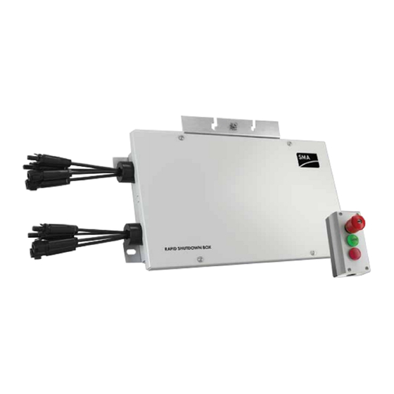
SMA Solar Technology America LLC 4 Product Description Product Description Rapid Shutdown System The Rapid Shutdown System consists of one or more Rapid Shutdown Boxes and one Rapid Shutdown Controller. PV systems equipped with the Rapid Shutdown System satisfy the requirements of UL 1741, Second Edition 2015 and Canadian Electrical Code 2015. - Page 12 4 Product Description SMA Solar Technology America LLC Design of the Rapid Shutdown Box and Rapid Shutdown Controller Figure 3 : Design of the Rapid Shutdown Box and Rapid Shutdown Controller Position Designation DC connection for the input strings Rapid Shutdown Box type label...
-
Page 13: Mounting
SMA Solar Technology America LLC 5 Mounting Mounting Requirements for Mounting Requirements for the mounting location: WARNING Danger to life due to fire or explosion Despite careful construction, electrical devices can cause fires. • Do not mount the Rapid Shutdown Box or Rapid Shutdown Controller in areas containing highly flammable materials or gases. -
Page 14: Mounting The Rapid Shutdown Box On A Mounting System
5 Mounting SMA Solar Technology America LLC Dimensions for mounting the Rapid Shutdown Box: Figure 4 : Position of the anchoring points of the Rapid Shutdown Box Permitted and prohibited mounting positions: ☐ The Rapid Shutdown Box and Rapid Shutdown Controller may only be mounted in a permissible position. - Page 15 SMA Solar Technology America LLC 5 Mounting WARNING Risk of falling when working on the roof There is a risk of falling or slipping when working on the rooftop. Observe the applicable accident prevention regulations for work on rooftops. • Before stepping on the rooftop, ensure the load bearing capacity of all parts subjected to load.
-
Page 16: Mounting The Rapid Shutdown Box With Mounting Brackets
5 Mounting SMA Solar Technology America LLC 3. Attach the Rapid Shutdown Box using suitable washers and nuts. 4. Ensure that the Rapid Shutdown Box is securely attached. Mounting the Rapid Shutdown Box with Mounting Brackets If you would like to mount the Rapid Shutdown Box on the wall or directly on the roof, proceed as described in the following. -
Page 17: Mounting The Rapid Shutdown Controller
SMA Solar Technology America LLC 5 Mounting 5. Align the Rapid Shutdown box over the drill holes and attach it using suitable screws and washers. Mounting the Rapid Shutdown Controller Additionally required mounting material (not included in the scope of delivery): ☐... -
Page 18: Electrical Connection
• Do not open the Rapid Shutdown Box during rain, snow or high levels of humidity (> 95%). • Only use listed rain-tight or liquid-tight conduit fittings to attach the conduits to the enclosure. SMA recommends using conduit fittings with flat, pliable, thick rubber sealing gaskets. The sealings should be roughly 2.54 mm (0.1 in / in) in thickness. -
Page 19: Overview Of The Rapid Shutdown Box Connection Area
SMA Solar Technology America LLC 6 Electrical Connection Overview of the Rapid Shutdown Box Connection Area 6.2.1 Exterior View Figure 6 : Exterior view of the Rapid Shutdown Box Position Designation DC connection for the input strings 1 and 2, channel A... -
Page 20: Interior View
6 Electrical Connection SMA Solar Technology America LLC 6.2.2 Interior View Figure 7 : Connection area inside the Rapid Shutdown Box Position Designation Terminal block for the connection of the first output string, channel A Equipment Ground Bar Terminal block for the connection of the Rapid Shutdown Controller and/or... - Page 21 SMA Solar Technology America LLC 6 Electrical Connection Procedure: 1. Place a washer onto the thread. 2. Position the equipment grounding conductor horizontally below or above the thread. 3. Place the clamping bracket onto the thread and over the equipment grounding conductor.
-
Page 22: Connecting The Rapid Shutdown Box And Rapid Shutdown Controller Together
6 Electrical Connection SMA Solar Technology America LLC Connecting the Rapid Shutdown Box and Rapid Shutdown Controller Together Additionally required material (not included in the scope of delivery): ☐ Conduit: either a separate conduit (trade size: 16 mm (0.5 in) or smaller with suitable reducer bush) or use the conduit of the output strings to lay the conductors. - Page 23 SMA Solar Technology America LLC 6 Electrical Connection Requirement: ☐ All electrical installations must be carried out in accordance with the locally applicable ® electrical standards and the National Electrical Code ANSI/NFPA 70 or the Canadian ® Electrical Code CSA C22.1.
- Page 24 6 Electrical Connection SMA Solar Technology America LLC Procedure: 1. Unscrew the four screws of the Rapid Shutdown Box enclosure lid using a hex socket screwdriver (TX 25) and remove the enclosure lid. 2. If the Rapid Shutdown Controller conductors are led into a separate conduit, remove the sealing plug from one of the two enclosure openings with sealing plugs.
- Page 25 SMA Solar Technology America LLC 6 Electrical Connection 12. Plug the five-pole plug with the connected conductors into the lower pin row of the terminal block RSC. 13. If there is only one Rapid Shutdown Box in the system, plug the second five-pole plug into the upper row of the terminal block RSC and place a jumper wire between pins 3 and 4.
- Page 26 6 Electrical Connection SMA Solar Technology America LLC Information on laying tray cables for exposed run (TC-ER) The procedure for using conduits is described in this section. Instead of conduits, you can also use tray cables for exposed run (TC-ER).
-
Page 27: Connecting Rapid Shutdown Boxes Together
SMA Solar Technology America LLC 6 Electrical Connection NOTICE Damage to the Rapid Shutdown Controller due to moisture penetration Moisture ingress can damage the Rapid Shutdown Controller and impair its functionality. • Place the upper enclosure part onto the lower enclosure part and tighten the four screws using a cross-head screwdriver (PZ 2) - Page 28 6 Electrical Connection SMA Solar Technology America LLC Information on laying tray cables for exposed run (TC-ER) The procedure for using conduits is described in this section. Instead of conduits, you can also use tray cables for exposed run (TC-ER).
- Page 29 SMA Solar Technology America LLC 6 Electrical Connection 5. Lead a silicone tube over the conductors inside the Rapid Shutdown Box. 6. Strip off the conductor insulation by 8 mm (0.31 in). 7. In the case of fine stranded wire, provide each conductor with a bootlace ferrule.
-
Page 30: Connecting The Strings To Rapid Shutdown Box
6 Electrical Connection SMA Solar Technology America LLC Connecting the Strings to Rapid Shutdown Box Up to four input strings and two output strings can be connected to the Rapid Shutdown Box. In the Rapid Shutdown Box, two of the four input strings are connected in parallel. The input strings must be connected to the DC conductors fitted with MC4 connectors that lead from the Rapid Shutdown Box. - Page 31 SMA Solar Technology America LLC 6 Electrical Connection Procedure: DANGER Danger to life due to high voltages of the PV array When exposed to sunlight, the PV array generates dangerous DC voltage which is present in the DC conductors. Touching the DC conductors can lead to lethal electric shocks.
- Page 32 6 Electrical Connection SMA Solar Technology America LLC CAUTION Danger of pinching fingers when the terminal block locking levers snap shut The locking levers close by snapping down fast and hard. • Press the locking levers of the terminal block A down with your thumb only. When doing so, ensure that your fingers can not be pinched when the locking levers snap into place.
- Page 33 SMA Solar Technology America LLC 6 Electrical Connection Connecting the Input Strings Requirements: ☐ The two PV strings of each separate input are connected in parallel inside the Rapid Shutdown Box. For the parallel connection of the input strings, a correct dimensioning of the strings must be used.
-
Page 34: Commissioning The Rapid Shutdown System
7 Commissioning the Rapid Shutdown System SMA Solar Technology America LLC Commissioning the Rapid Shutdown System 1. Commission all inverters in the system (see inverter manual). 2. Check whether the inverter to which the strings of the Rapid Shutdown Box are connected starts feed-in operation. -
Page 35: Checking The Function Of The Rapid Shutdown System
SMA Solar Technology America LLC 8 Checking the Function of the Rapid Shutdown System Checking the Function of the Rapid Shutdown System The Rapid Shutdown System is supplied via the PV array. If there is insufficient irradiation on the PV array, the supply voltage of the Rapid Shutdown System is too low and the function of the Rapid Shutdown System is not able to be checked. -
Page 36: Operating The Rapid Shutdown Controller
9 Operating the Rapid Shutdown Controller SMA Solar Technology America LLC Operating the Rapid Shutdown Controller Triggering the Rapid Shutdown Function • Press the emergency switch on the Rapid Shutdown Controller. ☑ The red LED on the Rapid Shutdown Controller lights briefly or flashes. The Rapid Shutdown Box reduces the voltage on the output string side. -
Page 37: Decommissioning The Rapid Shutdown System
SMA Solar Technology America LLC 10 Decommissioning the Rapid Shutdown System 10 Decommissioning the Rapid Shutdown System Procedure: DANGER Danger to life due to high voltages of the PV array When exposed to sunlight, the PV array generates dangerous DC voltage which is present in the DC conductors. - Page 38 10 Decommissioning the Rapid Shutdown System SMA Solar Technology America LLC 8. Hang the enclosure lid in the bracket of the upper enclosure edge and tighten the four screws using a hex socket screwdriver (TX 25) (torque: 6 Nm ± 0.6 Nm (53 in-lb ± 5 in-lb)).
- Page 39 SMA Solar Technology America LLC 10 Decommissioning the Rapid Shutdown System 15. Place the upper enclosure part onto the lower enclosure part and tighten the four screws using a cross-head screwdriver (PZ 2). Installation Manual RSS-US-IA-xx-14...
-
Page 40: Technical Data
11 Technical Data SMA Solar Technology America LLC 11 Technical Data 11.1 Rapid Shutdown Box Maximum input voltage 600 V Input voltage range 110 V to 600 V Nominal current per channel 20 A Maximum input short-circuit current per channel 36 A Conductor type for the connection of the output... - Page 41 SMA Solar Technology America LLC 11 Technical Data Maximum operating altitude above mean sea 3000 m (9843 ft) level (MSL) Enclosure degree of protection according to UL 50 Torque of the upper enclosure lid screws 1.8 Nm (16 in-lb) Installation Manual RSS-US-IA-xx-14...
-
Page 42: Contact
SMA Solar Technology America LLC 12 Contact If you have technical problems with our products, please contact the SMA Service Line. We require the following information in order to provide you with the necessary assistance: • Serial number of the Rapid Shutdown Box •... -
Page 43: Compliance Information
• Connect the equipment into an outlet on a circuit different from that to which the receiver is connected. • Consult the dealer or an experienced radio/TV technician for help. Changes or modifications made to this equipment not expressly approved by SMA Solar Technology America LLC may void the FCC authorization to operate this equipment. IC Compliance This Class B digital apparatus complies with Canadian ICES-003. -
Page 44: Disposiciones Legales
SMA no será responsable por ningún daño, ya sea indirecto, incidental o resultante, como consecuencia de confiar en el material que se presenta, incluyendo, aunque no exclusivamente, omisiones, errores tipográficos, aritméticos o de listado en el material del... -
Page 45: Instrucciones De Seguridad Importantes
Una advertencia describe un peligro que puede causar lesiones al usuario o daños materiales. Llama la atención sobre un procedimiento o una actividad que, de no realizarse correctamente, puede causar lesiones al usuario o daños materiales en productos de SMA o productos conectados a estos. - Page 46 Instrucciones de seguridad importantes SMA Solar Technology America LLC Observar las instrucciones de uso Lea la documentación del producto antes de trabajar con él. Siga todas las precauciones e instrucciones como se describen en la documentación. RSS-US-IA-xx-14 Instrucciones de instalación...
-
Page 47: Indicaciones Generales
SMA no asume responsabilidad alguna relativa al cumplimiento o al incumplimiento de la legislación o las disposiciones relacionadas con la instalación del producto. - Page 48 Índice SMA Solar Technology America LLC Índice Indicaciones sobre este documento ........50 Área de validez......................50 Grupo de destinatarios....................50 Símbolos ........................50 Nomenclatura ......................50 Seguridad ................. 51 Uso previsto........................ 51 Indicaciones de seguridad ..................52 Contenido de la entrega............53 Descripción del producto............
- Page 49 SMA Solar Technology America LLC Índice 10 Puesta fuera de servicio del Rapid Shutdown System..80 11 Datos técnicos................83 11.1 Rapid Shutdown Box ....................83 11.2 Rapid Shutdown Controller ..................83 12 Contacto ..................85 13 Información de cumplimiento ..........86 Instrucciones de instalación...
-
Page 50: Indicaciones Sobre Este Documento
Indicaciones sobre este documento Área de validez Este documento es aplicable a estos modelos: • RSB-2S-US-10 (SMA Rapid Shutdown Box) • RSC-1X-US-10 (SMA Rapid Shutdown Controller) Grupo de destinatarios Las actividades descritas en este documento deben realizarlas exclusivamente especialistas que han de contar con esta cualificación:... -
Page 51: Seguridad
Para realizar cualquier intervención en el producto, como modificaciones o remodelaciones, deberá contar con el permiso expreso y por escrito de SMA. Los cambios no autorizados conllevan la pérdida de los derechos de garantía, así como la extinción de la autorización de operación. -
Page 52: Indicaciones De Seguridad
2 Seguridad SMA Solar Technology America LLC Indicaciones de seguridad Este capítulo contiene indicaciones de seguridad que deben observarse siempre en todos los trabajos que se realizan en el producto y con el producto. Para evitar daños personales y materiales y garantizar el funcionamiento permanente del producto, lea detenidamente este capítulo y cumpla siempre las indicaciones de seguridad. -
Page 53: Contenido De La Entrega
SMA Solar Technology America LLC 3 Contenido de la entrega Contenido de la entrega Compruebe que el contenido de la entrega esté completo y que no presente daños externos visibles. En caso de que no esté completo o presente daños, póngase en contacto con su distribuidor. -
Page 54: Descripción Del Producto
4 Descripción del producto SMA Solar Technology America LLC Descripción del producto Rapid Shutdown System El Rapid Shutdown System se compone de una o varias Rapid Shutdown Box y un Rapid Shutdown Controller. El Rapid Shutdown System cumple con los requisitos de la UL 1741, Second Edition 2015, y del Canadian Electrical Code 2015 El Rapid Shutdown Controller sirve para activar y desactivar el Rapid Shutdown System así... - Page 55 SMA Solar Technology America LLC 4 Descripción del producto Estructura de la Rapid Shutdown Box y del Rapid Shutdown Controller Imagen 3 : Estructura de la Rapid Shutdown Box y del Rapid Shutdown Controller Posición Denominación Conexión de CC de los strings de entrada Placa de características de la Rapid Shutdown Box...
-
Page 56: Montaje
5 Montaje SMA Solar Technology America LLC Montaje Requisitos para el montaje Requisitos del lugar de montaje: ADVERTENCIA Peligro de muerte por fuego o explosión A pesar de estar cuidadosamente construidos, los equipos eléctricos pueden originar incendios. • No instale la Rapid Shutdown Box ni el Rapid Shutdown Controller en áreas en las que se encuentren materiales fácilmente inflamables o gases combustibles. -
Page 57: Montaje De La Rapid Shutdown Box Con Carril De Perfil
SMA Solar Technology America LLC 5 Montaje Dimensiones para el montaje de la Rapid Shutdown Box: Imagen 4 : Posición de los puntos de fijación de la Rapid Shutdown Box Posiciones de montaje permitidas y no permitidas: ☐ La Rapid Shutdown Box y el Rapid Shutdown Controller deben instalarse siempre en una posición autorizada para garantizar que no entre humedad. - Page 58 5 Montaje SMA Solar Technology America LLC ADVERTENCIA Peligro de caída durante los trabajos en el tejado Cuando se trabaja sobre un tejado existe el riesgo de que se produzcan caídas y resbalones. Cuando vaya a trabajar en el tejado, tenga en cuenta la normativa de prevención de accidentes vigentes.
-
Page 59: Montaje De La Rapid Shutdown Box Con Bridas De Sujeción
SMA Solar Technology America LLC 5 Montaje 3. Fije la Rapid Shutdown Box con las arandelas y tuercas adecuadas. 4. Asegúrese de que la Rapid Shutdown Box esté bien fijada. Montaje de la Rapid Shutdown Box con bridas de sujeción Si desea montar la Rapid Shutdown Box en la pared o directamente sobre el tejado, debe proceder según se describe a continuación. -
Page 60: Montaje Del Rapid Shutdown Controller
5 Montaje SMA Solar Technology America LLC 5. Coloque la Rapid Shutdown Box en los agujeros y fíjela con los tornillos y las arandelas adecuados. Montaje del Rapid Shutdown Controller Material de montaje adicional necesario (no incluido en el contenido de la entrega): ☐... -
Page 61: Conexión Eléctrica
Las juntas deben tener un grosor de unos 2,54 mm (0,1 in / in). SMA desaconseja el uso de juntas finas y duras (suelen ser de color amarillo o verde), ya que para esta utilización este tipo de juntas por lo general no ofrece un cierre estanco fiable. -
Page 62: Vista General De Las Áreas De Conexión De La Rapid Shutdown Box
6 Conexión eléctrica SMA Solar Technology America LLC Vista general de las áreas de conexión de la Rapid Shutdown Box 6.2.1 Vista exterior Imagen 6 : Vista exterior de la Rapid Shutdown Box Posición Denominación Conexión de CC de los strings de entrada 1 y 2, Channel A Conexión de CC de los strings de entrada 3 y 4, Channel B... -
Page 63: Vista Interior
SMA Solar Technology America LLC 6 Conexión eléctrica 6.2.2 Vista interior Imagen 7 : Áreas de conexión en el interior de la Rapid Shutdown Box Posición Denominación Caja de bornes para conectar el primer string de salida, Channel A Barra de puesta a tierra del equipo... - Page 64 6 Conexión eléctrica SMA Solar Technology America LLC Procedimiento: 1. Coloque una arandela en la rosca. 2. Coloque el conductor de puesta a tierra del equipo en horizontal por debajo o por encima de la rosca. 3. Coloque la abrazadera sobre la rosca y sobre el conductor de puesta a tierra del equipo.
-
Page 65: Conexión Entre Sí De Rapid Shutdown Box Y Rapid Shutdown Controller
SMA Solar Technology America LLC 6 Conexión eléctrica Conexión entre sí de Rapid Shutdown Box y Rapid Shutdown Controller Material adicional necesario (no incluido en el contenido de la entrega): ☐ Conducto para cables: O bien tienda un conducto para cables propio (tamaño comercial: 16 mm [0,5 in] o inferior con reductores adecuados) o tienda los conductores conjuntamente en el conducto para cables de los strings de salida. - Page 66 6 Conexión eléctrica SMA Solar Technology America LLC Requisito: ☐ Todas las instalaciones eléctricas deben realizarse conforme a la normativa local vigente y al ® ® código National Electrical Code ANSI/NFPA 70 o al Canadian Electrical Code CSA C22.1. Procedimiento: Si su Rapid Shutdown System dispone de varias Rapid Shutdown Box, conecte solamente la primera Rapid Shutdown Box con el Rapid Shutdown Controller.
- Page 67 SMA Solar Technology America LLC 6 Conexión eléctrica Procedimiento: 1. Suelte los cuatro tornillos de la tapa de la carcasa de la Rapid Shutdown Box con un destornillador hexagonal (TX 25) y retire la tapa. 2. Si los conductores del Rapid Shutdown Controller están tendidos en un conducto para cables propio, retire el sellador de una de las dos aberturas en la carcasa con selladores.
- Page 68 6 Conexión eléctrica SMA Solar Technology America LLC 12. Introduzca el conector de cinco polos con los conductores conectados en la fila inferior de patillas de la caja de bornes RSC. 13. Si el sistema solo dispone de una Rapid Shutdown...
- Page 69 SMA Solar Technology America LLC 6 Conexión eléctrica Indicación para el tendido de Tray Cables for exposed run (TC-ER) En este capítulo se describe si se utilizan conductos para cables. En lugar de conductos para cables también pueden usarse Tray Cable for exposed run (TC-ER).
-
Page 70: Conexión Entre Sí De Las Rapid Shutdown Box
6 Conexión eléctrica SMA Solar Technology America LLC PRECAUCIÓN Daños en el Rapid Shutdown Controller por penetración de humedad Si penetra humedad en la Rapid Shutdown Controller, éste podría resultar dañado y sus funciones podrían verse limitadas. • Coloque la parte superior de la carcasa... - Page 71 SMA Solar Technology America LLC 6 Conexión eléctrica ☐ Longitud máxima de los conductores entre dos Rapid Shutdown Box: 50 m (164 ft) ☐ Longitud máxima de los conductores entre la primera Rapid Shutdown Box y la última Rapid Shutdown Box: 100 m (328 ft) Indicación para el tendido de Tray Cables for exposed run (TC-ER)
- Page 72 6 Conexión eléctrica SMA Solar Technology America LLC 5. Dentro de la Rapid Shutdown Box, cubra los conductores con un tubo de silicona. 6. Pele 8 mm (0,31 in) de los conductores. 7. En los cordones finos, remate los conductores con una virola.
-
Page 73: Conexión De Los Strings A La Rapid Shutdown Box
SMA Solar Technology America LLC 6 Conexión eléctrica Conexión de los strings a la Rapid Shutdown Box Tiene la opción de conectar hasta cuatro strings de entrada y dos strings de salida a la Rapid Shutdown Box. En la Rapid Shutdown Box se conectan en paralelo dos de los cuatro strings de entrada. - Page 74 6 Conexión eléctrica SMA Solar Technology America LLC Procedimiento: PELIGRO Peligro de muerte por altas tensiones del generador fotovoltaico Cuando recibe luz solar, el generador fotovoltaico produce una tensión de CC peligrosa que se acopla a los conductores de CC. El contacto con dichos conductores de CC puede causar descargas eléctricas mortales.
- Page 75 SMA Solar Technology America LLC 6 Conexión eléctrica ATENCIÓN Peligro de aplastamiento de los dedos por cerrarse de golpe las palancas de protección de la caja de bornes Las palancas de protección se cierran de golpe, muy rápidamente y con fuerza.
- Page 76 6 Conexión eléctrica SMA Solar Technology America LLC Conexión de los strings de entrada Requisitos: ☐ Los dos strings de cada entrada se conectan en paralelo en la Rapid Shutdown Box. Para la conexión en paralelo de los strings de entrada es necesario dimensionar debidamente los strings.
-
Page 77: Puesta En Marcha Del Rapid Shutdown System
SMA Solar Technology America LLC 7 Puesta en marcha del Rapid Shutdown System Puesta en marcha del Rapid Shutdown System 1. Ponga en marcha todos los inversores de la planta (consulte las instrucciones del inversor). 2. Compruebe si el inversor al que están conectados los strings de la Rapid Shutdown Box inicia el funcionamiento de inyección. -
Page 78: Comprobación Del Correcto Funcionamiento Del Rapid Shutdown System
8 Comprobación del correcto funcionamiento del Rapid Shutdown SMA Solar Technology America LLC System Comprobación del correcto funcionamiento del Rapid Shutdown System El Rapid Shutdown System se abastece del generador fotovoltaico. Si no hay suficiente irradiación en el generador fotovoltaico, la tensión de alimentación del Rapid Shutdown System es muy baja y no será... -
Page 79: Manejo Del Rapid Shutdown Controller
SMA Solar Technology America LLC 9 Manejo del Rapid Shutdown Controller Manejo del Rapid Shutdown Controller Activación de la función Rapid Shutdown • Pulse la parada de emergencia del Rapid Shutdown Controller. ☑ El led rojo del Rapid Shutdown Controller se ilumina brevemente o parpadea. La Rapid Shutdown Box reduce la tensión en el lado de los strings de salida. -
Page 80: Puesta Fuera De Servicio Del Rapid Shutdown System
10 Puesta fuera de servicio del Rapid Shutdown System SMA Solar Technology America LLC 10 Puesta fuera de servicio del Rapid Shutdown System Procedimiento: PELIGRO Peligro de muerte por altas tensiones del generador fotovoltaico Cuando recibe luz solar, el generador fotovoltaico produce una tensión de CC peligrosa que se acopla a los conductores de CC. - Page 81 SMA Solar Technology America LLC 10 Puesta fuera de servicio del Rapid Shutdown System 8. Enganche la tapa de la carcasa en la lengüeta del borde superior de la carcasa y apriete los cuatro tornillos con un destornillador hexagonal (TX 25) (par de apriete: 6 Nm ±...
- Page 82 10 Puesta fuera de servicio del Rapid Shutdown System SMA Solar Technology America LLC 15. Coloque la parte superior de la carcasa encima de la parte inferior de la carcasa y apriete los cuatro tornillos con un destornillador de estrella Pozidriv (PZ 2).
-
Page 83: Datos Técnicos
SMA Solar Technology America LLC 11 Datos técnicos 11 Datos técnicos 11.1 Rapid Shutdown Box Tensión de entrada máxima 600 V Intervalo de tensión de entrada 110 V a 600 V Corriente nominal por canal 20 A Corriente máxima de entrada de cortocircuito 36 A por canal Tipo de conductor para la conexión de los... - Page 84 11 Datos técnicos SMA Solar Technology America LLC Altitud de funcionamiento máxima sobre el nivel 3000 m (9843 ft) del mar Tipo de protección de la carcasa según UL50 Par de apriete de los tornillos de la parte supe- 1,8 Nm (16 in-lb) rior de la carcasa RSS-US-IA-xx-14 Instrucciones de instalación...
-
Page 85: Contacto
12 Contacto Si surge algún problema técnico con nuestros productos, póngase en contacto con el Servicio Técnico de SMA. Para ayudarle de forma eficaz, necesitamos que nos facilite estos datos: • Número de serie de la Rapid Shutdown Box • Número de serie del Rapid Shutdown Controller... -
Page 86: Información De Cumplimiento
• Connect the equipment into an outlet on a circuit different from that to which the receiver is connected. • Consult the dealer or an experienced radio/TV technician for help. Changes or modifications made to this equipment not expressly approved by SMA Solar Technology America LLC may void the FCC authorization to operate this equipment. IC Compliance This Class B digital apparatus complies with Canadian ICES-003. -
Page 87: Dispositions Légales
Les spécifications peuvent être modifiées sans préavis. Tous les efforts ont été mis en œuvre pour que ce document soit élaboré avec le plus grand soin et tenu aussi à jour que possible. SMA Solar Technology America, LLC et/ou SMA Solar Technology Canada Inc. avertissent toutefois les lecteurs qu’elles se réservent le droit d’apporter des modifications aux présentes spécifications sans... - Page 88 Dispositions légales SMA Solar Technology America LLC État actuel : 29/08/2017 Copyright © 2017 SMA Solar Technology America LLC. Tous droits réservés. RSS-US-IA-xx-14 Instructions d’installation...
-
Page 89: Consignes De Sécurité Importantes
Une mise en garde decrit un danger entraînant des blessures corporelles ou dommages matériels. La mise en garde indique une action qui risque les blessures corporelles ou les dommages matériels aux produits SMA ou aux produits raccordés en cas de non-respect. Symbole Description « DANGER »... - Page 90 Consignes de sécurité importantes SMA Solar Technology America LLC Consulter les instructions d’utilisation Lisez la documentation relative au produit avant de travailler sur ce dernier. Respectez toutes les consignes de sécurité et instructions figurant dans la docu- mentation. RSS-US-IA-xx-14 Instructions d’installation...
-
Page 91: Avertissements D'ordre Général
à l’installation et à l’utilisation du produit, notamment les normes en vigueur relatives à la sécurité électrique. L’installation doit être réalisée conformément aux législations, dispositions, prescriptions et normes en vigueur sur place. SMA décline toute responsabilité pour la conformité ou non-conformité à ces législations ou dispositions en relation avec l’installation du produit. - Page 92 Table des matières SMA Solar Technology America LLC Table des matières Remarques relatives à ce document........94 Champ d’application ....................94 Groupe cible ......................94 Symboles ........................94 Nomenclature......................94 Sécurité..................95 Utilisation conforme ....................95 Consignes de sécurité....................96 Contenu de la livraison............
- Page 93 SMA Solar Technology America LLC Table des matières Mise hors service du Rapid Shutdown System......125 Caractéristiques techniques.............128 Rapid Shutdown Box ....................128 Rapid Shutdown Controller ..................128 Contact ..................130 Informations sur le respect des spécifications .......131 Instructions d’installation RSS-US-IA-xx-14...
-
Page 94: Remarques Relatives À Ce Document
Remarques relatives à ce document Champ d’application Ce document est valable pour les types d’appareil suivants : • RSB-2S-US-10 (SMA Rapid Shutdown Box) • RSC-1X-US-10 (SMA Rapid Shutdown Controller) Groupe cible Les opérations décrites dans le présent document doivent uniquement être réalisées par un personnel qualifié. -
Page 95: Sécurité
Les interventions sur le produit (modifications ou transformations, par exemple) ne sont autorisées qu’après accord écrit de SMA. Toute intervention non autorisée entraîne l’annulation de la garantie légale et commerciale et, en règle générale, le retrait de l’autorisation d’exploitation. SMA décline toute responsabilité... -
Page 96: Consignes De Sécurité
2 Sécurité SMA Solar Technology America LLC Les documents joints font partie intégrante du produit. Les documents doivent être lus, respectés et rester accessibles à tout moment. La plaque signalétique doit être apposée en permanence sur le produit. Consignes de sécurité... -
Page 97: Contenu De La Livraison
Contenu de la livraison Vérifiez si la livraison est complète et ne présente pas de dommages apparents. En cas de livraison incomplète ou de dommages, contactez votre revendeur. Figure 1 : Éléments du contenu de livraison Position Quantité Désignation Rapid Shutdown Box Rondelle à... -
Page 98: Description Du Produit
2 Description du produit SMA Solar Technology America LLC Description du produit Rapid Shutdown System Le Rapid Shutdown System est composé d’une ou de plusieurs Rapid Shutdown Box et d’un Rapid Shutdown Controller. Le Rapid Shutdown System permet de satisfaire aux exigences conformes à... -
Page 99: Structure De La Rapid Shutdown Box Et Du Rapid Shutdown Controller
SMA Solar Technology America LLC 2 Description du produit Structure de la Rapid Shutdown Box et du Rapid Shutdown Controller Figure 3 : Structure de la Rapid Shutdown Box et du Rapid Shutdown Controller Position Désignation Raccordement DC pour les strings d’entrée Plaque signalétique de la Rapid Shutdown Box... -
Page 100: Montage
3 Montage SMA Solar Technology America LLC Montage Conditions requises pour le montage Exigences relatives au lieu de montage : AVERTISSEMENT Danger de mort par incendie ou explosion En dépit d’un assemblage réalisé avec le plus grand soin, tout appareil électrique peut présenter un risque d’incendie. -
Page 101: Montage De La Rapid Shutdown Box Avec Profilé
SMA Solar Technology America LLC 3 Montage Cotes de montage de la Rapid Shutdown Box : Figure 4 : Position des points de fixation de la Rapid Shutdown Box Positions de montage autorisées et non autorisées : ☐ La Rapid Shutdown Box et le Rapid Shutdown Controller ne doivent être montés que dans la position autorisée. -
Page 102: Risque De Chute Lors D'interventions Sur Le Toit
3 Montage SMA Solar Technology America LLC AVERTISSEMENT Risque de chute lors d’interventions sur le toit Lors d’interventions sur le toit, il existe un risque de chute et de glissade. Respectez la réglementation en vigueur relative à la prévention des accidents lors d’interventions sur le toit. -
Page 103: Montage De La Rapid Shutdown Box Avec Des Supports De Fixation
SMA Solar Technology America LLC 3 Montage 3. Fixez la Rapid Shutdown Box avec des rondelles et des écrous appropriés. 4. Assurez-vous que la Rapid Shutdown Box est bien serrée. Montage de la Rapid Shutdown Box avec des supports de fixation Si vous souhaitez monter la Rapid Shutdown Box au mur ou directement sur le toit, vous devez procéder comme décrit ci-après. -
Page 104: Montage Du Rapid Shutdown Controller
3 Montage SMA Solar Technology America LLC 5. Placez la Rapid Shutdown Box au niveau des trous à percer et vissez-la avec des vis et des rondelles adaptées. Montage du Rapid Shutdown Controller Matériel de montage supplémentaire nécessaire (non compris dans le contenu de livraison) :... -
Page 105: Raccordement Électrique
• Pour fixer les tuyaux à câbles sur le boîtier, utilisez uniquement des manchons étanches à l’eau ou résistants à l’humidité listés. SMA recommande l’utilisation de manchons dotés de joints en caoutchouc épais, plats et souples. Les joints doivent présenter une épaisseur d’env. -
Page 106: Vue D'ensemble Des Zones De Raccordement De La Rapid Shutdown Box
4 Raccordement électrique SMA Solar Technology America LLC Vue d’ensemble des zones de raccordement de la Rapid Shutdown Box 4.2.1 Vue extérieure Figure 6 : Vue extérieure de la Rapid Shutdown Box Position Désignation Raccordement DC pour les strings d’entrée 1 et 2, Channel A Raccordement DC pour les strings d’entrée 3 et 4, Channel B... -
Page 107: Vue Intérieure
SMA Solar Technology America LLC 4 Raccordement électrique 4.2.2 Vue intérieure Figure 7 : Zones de raccordement à l’intérieur de la Rapid Shutdown Box Position Désignation Plaque à bornes pour le raccordement du premier string de sortie, Channel A Equipment Ground Bar Plaque à... -
Page 108: Empêchement De La Corrosion Par Contact Par Pliage Du Conducteur De Mise À La Terre De L'équipement
4 Raccordement électrique SMA Solar Technology America LLC Procédure : 1. Placez une rondelle sur le filetage. 2. Placez le conducteur de mise à la terre de l’équipement à l’horizontale au-dessous ou au- dessus du filetage. 3. Placez le serre-câble sur le filetage et au-dessus du conducteur de mise à... -
Page 109: Raccordement De La Rapid Shutdown Box Et Du Rapid Shutdown Controller L'un À L'autre
SMA Solar Technology America LLC 4 Raccordement électrique Raccordement de la Rapid Shutdown Box et du Rapid Shutdown Controller l’un à l’autre Matériel supplémentaire nécessaire (non compris dans le contenu de livraison) : ☐ Tuyau à câbles : soit un propre tuyau à câbles (taille commerciale : 16 mm (0,5 in) ou de dimensions inférieures avec des raccords de réduction appropriés) soit posez les conducteurs... -
Page 110: Raccordement Des Conducteurs À La Rapid Shutdown Box
4 Raccordement électrique SMA Solar Technology America LLC Condition requise : ☐ Toutes les installations électriques doivent être réalisées conformément aux normes électriques ® en vigueur sur le site et au National Electrical Code ANSI/NFPA 70 ou au ® Canadian Electrical Code CSA C22.1. Procédure : Si plusieurs Rapid Shutdown Box sont présentes dans votre Rapid Shutdown System, raccordez seulement la première Rapid Shutdown Box au Rapid Shutdown Controller. - Page 111 SMA Solar Technology America LLC 4 Raccordement électrique Procédure : 1. Dévissez les 4 vis du couvercle du boîtier de la Rapid Shutdown Box à l’aide d’un tournevis pour vis à six pans creux (TX 25) et retirez le couvercle du boîtier. 2. Si les conducteurs du Rapid Shutdown Controller sont insérés dans un propre tuyau à câbles, retirez le bouchon d’étanchéité...
-
Page 112: Raccordement Des Conducteurs Au Rapid Shutdown Controller
4 Raccordement électrique SMA Solar Technology America LLC 12. Introduisez la fiche à 5 pôles avec les conducteurs raccordés dans la rangée de broches inférieure de la plaque à bornes RSC. 13. Si seulement une Rapid Shutdown Box est présente dans le système, enfichez la deuxième fiche à 5 pôles dans la rangée de broches supérieure de la... - Page 113 SMA Solar Technology America LLC 4 Raccordement électrique Remarque sur la pose des Tray Cables for exposed run (TC-ER) Ce chapitre décrit la procédure d’utilisation des tuyaux à câbles. À la place de tuyaux à câbles, vous pouvez également utiliser des Tray Cable for exposed run (TC-ER).
-
Page 114: Endommagement Du Rapid Shutdown Controller Dû À La Pénétration D'humidité
4 Raccordement électrique SMA Solar Technology America LLC PRUDENCE Endommagement du Rapid Shutdown Controller dû à la pénétration d’humidité La pénétration d’humidité dans le Rapid Shutdown Controller peut endommager celui-ci ou altérer son fonctionnement. • Mettez la partie supérieure du boîtier en place sur la partie inférieure du boîtier et... - Page 115 SMA Solar Technology America LLC 4 Raccordement électrique ☐ Longueur maximale autorisée des conducteurs entre 2 Rapid Shutdown Box : 50 m (164 ft) ☐ Longueur maximale autorisée des conducteurs de la première Rapid Shutdown Box jusqu’à la dernière Rapid Shutdown Box : 100 m (328 ft) Remarque sur la pose des Tray Cables for exposed run (TC-ER) Ce chapitre décrit la procédure d’utilisation des tuyaux à...
- Page 116 4 Raccordement électrique SMA Solar Technology America LLC 4. Sur la première Rapid Shutdown Box, introduisez les conducteurs jusqu’à la plaque à bornes RSC. 5. Introduisez une gaine en silicone par dessus les conducteurs au sein de la Rapid Shutdown Box.
-
Page 117: Raccordement Des Strings À La Rapid Shutdown Box
SMA Solar Technology America LLC 4 Raccordement électrique Raccordement des strings à la Rapid Shutdown Box Vous avez la possibilité de raccorder jusqu’à 4 strings d’entrée et jusqu’à 2 strings de sortie à la Rapid Shutdown Box. 2 des 4 strings d’entrée sont respectivement commutés en parallèle dans la Rapid Shutdown Box. -
Page 118: Danger De Mort Dû À De Hautes Tensions Du Générateur Photovoltaïque
4 Raccordement électrique SMA Solar Technology America LLC Procédure : DANGER Danger de mort dû à de hautes tensions du générateur photovoltaïque En cas d’ensoleillement, le générateur photovoltaïque produit une tension continue dangereuse dans les conducteurs DC. Le contact avec les conducteurs DC peut entraîner des chocs électriques susceptibles d’entraîner la mort. - Page 119 SMA Solar Technology America LLC 4 Raccordement électrique 8. Branchez les conducteurs du premier string de sortie à la plaque à bornes A. Pour cela, soulevez les leviers de sécurité jusqu’en butée et introduisez les conducteurs dans les bornes. Prenez garde ce faisant à...
-
Page 120: Danger De Mort Dû À De Hautes Tensions
4 Raccordement électrique SMA Solar Technology America LLC 13. Suspendez le couvercle du boîtier à la languette du bord supérieur du boîtier et serrez les 4 vis à l’aide d’un tournevis pour vis à six pans creux (TX 25) (couple de serrage : 6 Nm ± 0,6 Nm (53 in-lb ±... -
Page 121: Risque D'endommagement Des Connecteurs Mc4 Par Pénétration D'humidité
SMA Solar Technology America LLC 4 Raccordement électrique PRUDENCE Risque d’endommagement des connecteurs MC4 par pénétration d’humidité L’étanchéité des conducteurs MC4 n’est assurée que lorsque tous les connecteurs MC4 inutilisés qui dépassent de la Rapid Shutdown Box sont obturés par les bouchons d’étanchéité... -
Page 122: Mise En Service Du Rapid Shutdown System
5 Mise en service du Rapid Shutdown System SMA Solar Technology America LLC Mise en service du Rapid Shutdown System 1. Mettez en service tous les onduleurs de l’installation (voir documentation de l’onduleur). 2. Contrôlez si l’onduleur auquel sont raccordés les strings de la Rapid Shutdown Box démarre le mode d’injection. -
Page 123: Contrôle Du Fonctionnement Du Rapid Shutdown System
SMA Solar Technology America LLC 6 Contrôle du fonctionnement du Rapid Shutdown System Contrôle du fonctionnement du Rapid Shutdown System Le Rapid Shutdown System est alimenté par le générateur photovoltaïque. Si le rayonnement solaire sur le générateur photovoltaïque est insuffisant, la tension d’alimentation du Rapid Shutdown System est trop basse et le fonctionnement du Rapid Shutdown System ne peut pas être... -
Page 124: Commande Du Rapid Shutdown Controller
7 Commande du Rapid Shutdown Controller SMA Solar Technology America LLC Commande du Rapid Shutdown Controller Déclenchement de la fonction Rapid Shutdown • Actionnez la coupure d’urgence du Rapid Shutdown Controller. ☑ La DEL rouge du Rapid Shutdown Controller s’allume brièvement ou clignote. La Rapid Shutdown Box abaisse la tension sur le côté... -
Page 125: Mise Hors Service Du Rapid Shutdown System
SMA Solar Technology America LLC 8 Mise hors service du Rapid Shutdown System Mise hors service du Rapid Shutdown System Procédure : DANGER Danger de mort dû à de hautes tensions du générateur photovoltaïque En cas d’ensoleillement, le générateur photovoltaïque produit une tension continue dangereuse dans les conducteurs DC. - Page 126 8 Mise hors service du Rapid Shutdown System SMA Solar Technology America LLC 8. Suspendez le couvercle du boîtier à la languette du bord supérieur du boîtier et serrez les 4 vis à l’aide d’un tournevis pour vis à six pans creux (TX 25) (couple de serrage : 6 Nm ±...
- Page 127 SMA Solar Technology America LLC 8 Mise hors service du Rapid Shutdown System 15. Mettez la partie supérieure du boîtier en place sur la partie inférieure du boîtier et serrez les 4 vis à l’aide d’un tournevis cruciforme (PZ 2). Instructions d’installation...
-
Page 128: Caractéristiques Techniques
9 Caractéristiques techniques SMA Solar Technology America LLC Caractéristiques techniques Rapid Shutdown Box Tension d’entrée maximale 600 V Plage de tension d’entrée 110 V à 600 V Courant nominal par Channel 20 A Courant maximum de court-circuit d’entrée par 36 A Channel Type de conducteur pour le raccordement des... - Page 129 SMA Solar Technology America LLC 9 Caractéristiques techniques Plage de température de fonctionnement -25 °C à +70 °C (-13 °F à +158 °F) Altitude maximale d’exploitation au-dessus du 3000 m (9843 ft) niveau moyen de la mer Indice de protection du boîtier selon UL 50 Couple de serrage des vis de la partie supé- 1,8 Nm (16 in-lb)
-
Page 130: Contact
Contact En cas de problèmes techniques concernant nos produits, prenez contact avec le Service en Ligne de SMA. Nous avons besoin des données suivantes pour pouvoir assurer une assistance ciblée : • Numéro de série de la Rapid Shutdown Box • Numéro de série du Rapid Shutdown Controller... -
Page 131: Informations Sur Le Respect Des Spécifications
• Connect the equipment into an outlet on a circuit different from that to which the receiver is connected. • Consult the dealer or an experienced radio/TV technician for help. Changes or modifications made to this equipment not expressly approved by SMA Solar Technology America LLC may void the FCC authorization to operate this equipment. IC Compliance This Class B digital apparatus complies with Canadian ICES-003. - Page 132 www.SMA-Solar.com...