Table des Matières
Publicité
Les langues disponibles
Les langues disponibles
Liens rapides
Publicité
Chapitres
Table des Matières
Dépannage

Manuels Connexes pour MINN KOTA ENDURA C2


Sommaire des Matières pour MINN KOTA ENDURA C2
- Page 1 ENDURA C2 TRANSOM-MOUNT TROLLING MOTOR USER MANUAL...
- Page 2 A registration card is enclosed or you can complete registration on the internet at minnkotamotors.com. NOTE: Do not return your Minn Kota motor to your retailer. Your retailer is not authorized to repair or replace this unit. You may obtain service by: calling Minn Kota at (800) 227-6433;...
-
Page 3: Table Des Matières
TABLE OF CONTENTS Two-Year Limited Warranty Features Installation Battery & Wiring Installation Boat Rigging & Product Installation Conductor Gauge and Circuit Breaker Sizing Table Selecting the Correct the Batteries How to Connect Batteries Motor Wiring Diagram Using and Adjusting the Motor 10-11 Adjusting the Depth of the Motor Adjusting the Steering... -
Page 4: Two-Year Limited Warranty
MINN KOTA LIMITED LIFETIME WARRANTY ON COMPOSITE SHAFT JOME warrants to the original retail purchaser only that the composite shaft of the purchaser’s Minn Kota trolling motor will be materially free from defects in materials and workmanship appearing within the original purchaser’s lifetime. JOME will provide a new composite shaft, free of charge, to replace any composite shaft found by JOME to be defective during the term of this warranty. -
Page 5: Features
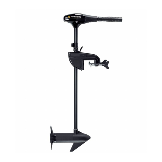
FEATURES Telescoping Handle Controls: On/Off, Speed, Forward/Reverse and Direction Adjustable Depth Collar Steering Tension Knob Quick Release Tilt Lever 10-Position Lever Lock Mounting Bracket Transom Clamp Screws Lifetime Warranty Flexible Composite Shaft Power Prop* Cool Quiet Power Motor Specifications subject to change without notice. *This diagram is for reference only and may differ from your actual motor. -
Page 6: Installation
INSTALLATION HANDLE INSTALLATION 1. Remove the wire clip from the ball detent located on the inner handle. 2. Install outer handle over inner handle. Position the handles so the ball detent and OFF are aligned. 3. Push the outer handle into the control box until handle “clicks” into place. The handle is held in place with locking fi ngers, so some force may be required to lock the handles together. -
Page 7: Battery & Wiring Installation
CAUTION: These guidelines apply to general rigging to support your Minn Kota motor. Powering multiple motors or additional electrical devices from the same power circuit may impact the recommended conductor gauge and circuit breaker size. If you are using wire longer than that provided with your unit, follow the conductor gauge and circuit breaker sizing table below. -
Page 8: Selecting The Correct The Batteries
• It is highly recommended that a circuit breaker or fuse be used with this trolling motor. Refer to “Conductor Gauge and Circuit Breaker Sizing Table” in the previous section to fi nd the appropriate circuit breaker or fuse for your motor. For motors requiring a 60-amp breaker, the Minn Kota MKR-19 60-amp circuit breaker is recommended. HOW TO CONNECT THE BATTERIES 12 VOLT SYSTEMS: 1. -
Page 9: Motor Wiring Diagram
MOTOR WIRING DIAGRAM SWITCH BLACK RED+ WHITE YELLOW BLACK- RED B+ BLACK B- MOTOR 12 VOLT DEEP CYCLE MARINE BATTERY minnkotamotors.com | 9 ©2014 Johnson Outdoors Marine Electronics, Inc. -
Page 10: Using And Adjusting The Motor
USING & ADJUSTING THE MOTOR TO ADJUST THE DEPTH OF THE MOTOR Depth Adjustment Knob When setting the depth be sure the top of the motor is submerged at least Steering Tension Knob 12” to avoid churning or agitation of surface water. The propeller must be completely submerged. -
Page 11: Bracket Adjustment
USING & ADJUSTING THE MOTOR BRACKET ADJUSTMENT You can lock your motor in a vertical position, angle it for shallow water or tilt it completely out of the water. 1. Firmly grasp the control head or composite shaft. 2. Press the tilt lever toward the shaft and hold to release the detent lock or T-bar to adjust the position of the mounting bracket. 3. -
Page 12: Service & Maintenance
SERVICE & MAINTENANCE PROPELLER REPLACEMENT TOOLS AND RESOURCES REQUIRED: Propeller • 7/16” Box End Wrench Slot End • Screwdriver (optional) Prop Nut CAUTION: Washer Disconnect the motor from the battery before beginning any prop work or maintenance. NOTE: The propeller on your motor may diff er from the one pictured. -
Page 13: Troubleshooting & Repair
AUTHORIZED SERVICE CENTERS Minn Kota has over 300 authorized service centers in the United States and Canada where you can purchase parts or get your products repaired. Please visit our Authorized Service Center page on our website to locate a service center in your area. -
Page 14: Parts Diagram
ENDURA C2 55 55 LBS THRU - 12 VOLT - 36”/42” SHA This page provides Minn Kota® WEEE compliance disassembly instructions. For more information about where you should dispose of your waste equipment for recycling and recovery and/ or your European Union member state requirements, please contact your dealer or distributor from which your product was purchased. -
Page 15: Parts List
990-067 HER — EEL THRU 2060215 CONTROL BOX COVER 990-070 HER — NY TRON 2065704 L COVER ENDURA C2 55 2097085 MOTOR SEMBLY 12V 3.62 5SPC FW 36” 2064028 SWITCH — FWD/REV 5 SP 2097086 MOTOR SEMBLY 12V 3.62 5SPC FW 42”... -
Page 16: Compliance Statements
Minn Kota motors are not subject to the disposal regulations EAG-VO (electric devices directive) that implements the WEEE directive. Nevertheless never dispose of your Minn Kota motor in a garbage bin but at the proper place of collection of your local town council. -
Page 17: Notes
NOTES minnkotamotors.com | 17 ©2014 Johnson Outdoors Marine Electronics, Inc. -
Page 18: Recommended Accessories
Stop buying new batteries and start taking care of the ones you’ve got. Many chargers can actually damage your battery over time – creating shorter run times and shorter overall life. Digitally controlled Minn Kota chargers are designed to provide the fastest charge that protect and extend battery life. - Page 19 ENDURA C2 PROPULSEUR ÉLECTRIQUE À MONTAGE SUR ARCASSE MANUEL DE L’UTILISATEUR...
-
Page 20: Manuel Ce D'un Master (Ce/C-Tick Certified Models)
REMARQUE : ne pas retourner le moteur Minn Kota au détaillant. Le détaillant n’est pas autorisé à réparer ou à remplacer cet appareil. Pour le service : communiquer avec Minn Kota au +1 (800) 227-6433; retourner le moteur au Centre de service de l’usine de Minn Kota; envoyer ou apporter le moteur à... - Page 21 TABLE DES MATIÈRES Garantie Limitée de Deux Ans Caractéristiques Installation Installation de la Batterie et du Câblage 25-26 Gréement de l’embarcation et Installation du Produit Tableau des Dimensions de Gabarit des Conducteurs et Disjoncteurs Sélectionner une Batterie Adéquate Comment Raccorder la Batterie Schéma de Câblage du Moteur Utilisation et Réglage du Moteur 28-29...
-
Page 22: Garantie Limitée De Deux Ans
Les articles achetés à l’extérieur des États-Unis doivent être retournés, port payé avec la preuve d’achat (y compris la date d’achat et le numéro de série), à tout centre de service agréé Minn Kota dans le pays de l’achat. Le service au titre de la garantie peut être obtenu en communiquant avec le centre de service agréé... -
Page 23: Caractéristiques
CARACTÉRISTIQUES La poignée contrôle la fonction marche/arrêt, la vitesse, la marche avant/arrière et la direction Collier de profondeur réglable Bouton de tension Levier d’inclinaison à relâche rapide de la direction Support de montage du blocage de levier à 10 positions Vis de blocage du tableau arrière Arbre composite flexible garanti à... -
Page 24: Installation
INSTALLATION INSTALLATION DE LA POIGNÉE 1. Retirer l’agrafe en fi l de la détente à bille située sur la poignée intérieure. 2. Installer la poignée extérieure sur la poignée intérieure. Positionner les poignées de sorte que la détente à bille et le repère «OFF»... -
Page 25: Installation Des Batteries Et Du Câblage
é. Les spécifi cations suivantes sont seulement des lignes directrices générales: MISE EN GARDE!: ces lignes directrices s’appliquent au gréement général pour soutenir le moteur de Minn Kota. L’alimentation de multiples moteurs ou d’autres appareils électriques, à partir du même circuit d’alimentation, peut infl uer sur le gabarit de conducteurs et le dimensionnement des disjoncteurs recommandé. -
Page 26: Sélectionner Une Batterie Adéquate
• Il est fortement recommandé d’utiliser un disjoncteur ou un fusible avec ce propulseur électrique. Consulter le « Tableau des dimensions de gabarit des conducteurs et disjoncteurs » dans la section précédente pour trouver le disjoncteur ou fusible approprié convenant à votre moteur. Pour les moteurs nécessitant un disjoncteur de 60-A, le disjoncteur Minn Kota MKR-19 60-A est recommandé. -
Page 27: Schéma De Câblage Du Moteur
SCHÉMA DE CÂBLAGE DU MOTEUR INTERRUPTEUR NOIR ROUGE+ BLANC JAUNE NOIR- ROUGE B+ NOIR B- MOTEUR BATTERIE MARINE À DÉCHARGE PROFONDE 12 VOLT minnkotamotors.com | 27 ©2014 Johnson Outdoors Marine Electronics, Inc. -
Page 28: Utilisation Et Réglage Du Moteur
UTILISATION ET RÉGLAGE DU MOTEUR RÉGLAGE DE LA PROFONDEUR DU MOTEUR Bouton de réglage de la profondeur Au moment du réglage de la profondeur, s’assurer que le dessus du moteur Bouton de tension est immergé à au moins 12 po (30,5 cm) afi n d’éviter de faire tourbillonner de la direction ou d’agiter l’eau à... -
Page 29: Réglage Du Support
USING & ADJUSTING THE MOTOR RÉGLAGE DU SUPPORT Le moteur peut être fixé à la verticale, incliné en eaux peu profondes ou complètement incliné hors de l’eau. 1. Saisir fermement la tête de commande ou l’arbre composite. 2. Appuyer sur le levier d’inclinaison en direction de l’arbre et le maintenir pour libérer le cran d’arrêt ou la barre en T afi n de régler la position du support de montage. -
Page 30: Service Et Entretien
SERVICE ET ENTRETIEN REMPLACEMENT DE L’HÉLICE OUTILS ET RESSOURCES NÉCESSAIRES: Hélice • Clé à oeil de 11 mm (7/16 “) Fente à l’extrémité • Tournevis (facultatif) Écrou de l’hélice Rondelle MISE EN GARDE: Débrancher le moteur de la batterie avant d’eff ectuer tout travail ou entretien sur l’hélice. -
Page 31: Dépannage Et Réparation
FOIRE AUX QUESTIONS Notre site Web présente FAQ visant à répondre à toutes vos questions au sujet des produits Minn Kota. Veuillez visiter le site Web minnkotamotors.com, puis cliquer sur « Foire aux questions » pour trouver réponse à vos questions. -
Page 32: Schéma Des Pièces
ENDURA C2 55 POUSSÉE DE 55 LB - 12 VOLTS - ARBRE 36/42 PO Cette page fournit les consignes de dépose de Minn Kota® en conformité avec la directive DEEE. Pour de l’information supplémentaire sur l’endroit où vous pouvez vous débarrasser de l’équipement usagé... -
Page 33: Liste Des Pièces
2060215 COUVERCLE DE BOÎTE DE COMMANDE 2097085 ENSEMBLE MOTEUR 12V 3,62 5SPC FW 36” 2065704 DÉ LQUE DE COUVERCLE ENDURA C2 55 COMMUTATEUR – 5 RÉG G DE VIT SE DE 2097086 ENSEMBLE MOTEUR 12V 3,62 5SPC FW 42” 2064028 MARCHE AVANT/ARRIÈRE... -
Page 34: Déclaration De Conformité
Les moteurs Minn Kota ne sont pas soumis à la réglementation concernant l’élimination VGE-VO (directive pour les dispositifs électriques), qui transpose la directive DEEE. Néanmoins, ne jamais jeter le moteur Minn Kota dans une poubelle, mais plutôt à l’endroit approprié où s’eff ectue la collecte, recommandé par le conseil municipal local. -
Page 35: Remarques
REMARQUES minnkotamotors.com | 35 ©2014 Johnson Outdoors Marine Electronics, Inc. -
Page 36: Accessoires Recommandés
à la longue, pouvant entraîner une autonomie réduite et une durée de vie plus courte. Les chargeurs Minn Kota à commande numérique assurent une charge rapide pour une protection et une durée de vie prolongée.