Table des Matières
Publicité
Liens rapides
MANUAL
FILTAIR CAPTURE 5
ALUGUEL E VENDA DE MÁQUINAS DE
SOLDA E CORTE PLASMA
TODOS OS PROCESSOS DE SOLDAGEM
TRABALHAMOS EXCLUSIVAMENTE COM
AS MELHORES MÁQUINAS DO MUNDO
ASSESSORIA PARA PROCESSOS ESPECIAIS
TECNOLOGIA ATUALIZADA PARA
GARANTIR O MELHOR CUSTO BENEFÍCIO
AUMENTO DE PRODUTIVIDADE SOLDADOR-PEÇA
REDUÇÃO DE CUSTO COM ENERGIA
MIG MAG · TIG · ARCO SUBMERSO · MULTIPROCESSO · RETIFICADORAS CORTE PLASMA
INVERSORAS · ELETRODO · GERADORES DE ENERGIA · ROBÔS
www.aventa.com.br | contato@aventa.com.br
LOCAÇÃO E VENDA
MÁQUINAS DE SOLDA E CORTE
Publicité
Table des Matières

Manuels Connexes pour Miller FILTAIR Capture 5


Sommaire des Matières pour Miller FILTAIR Capture 5
- Page 1 MANUAL FILTAIR CAPTURE 5 LOCAÇÃO E VENDA MÁQUINAS DE SOLDA E CORTE ALUGUEL E VENDA DE MÁQUINAS DE SOLDA E CORTE PLASMA TODOS OS PROCESSOS DE SOLDAGEM TRABALHAMOS EXCLUSIVAMENTE COM AS MELHORES MÁQUINAS DO MUNDO ASSESSORIA PARA PROCESSOS ESPECIAIS TECNOLOGIA ATUALIZADA PARA GARANTIR O MELHOR CUSTO BENEFÍCIO...
- Page 2 OM-260 545A 2013−07 Processes Multiprocess Welding Description Mobile Weld Fume Extractor FILTAIR Capture 5 Fume Extractor Read And Save These Instructions File: Accessory Visit our website at www.MillerWelds.com...
- Page 3 We know you don’t have time to do it any other way. That’s why when Niels Miller first started building arc welders in 1929, he made sure his products offered long-lasting value and superior quality.
-
Page 4: Table Des Matières
TABLE OF CONTENTS SECTION 1 − SAFETY PRECAUTIONS - READ BEFORE USING ....... . . 1-1. -
Page 6: Section 1 − Safety Precautions - Read Before Using
SECTION 1 − SAFETY PRECAUTIONS - READ BEFORE USING fume 2013−02 Protect yourself and others from injury — read, follow, and save these important safety precautions and operating instructions. 1-1. Symbol Usage DANGER! − Indicates a hazardous situation which, if Indicates special instructions. -
Page 7: Arc Welding And Plasma Cutting Hazards
FALLING EQUIPMENT can injure. FIRE OR EXPLOSION hazard. D Use equipment of adequate capacity to lift and D Do not install or place unit on, over, or near support unit. combustible surfaces. D If using lift forks to move unit, be sure forks are D Do not install unit near flammables. - Page 8 D Do not use welder to thaw frozen pipes. FUMES AND GASES can be hazardous. D Remove stick electrode from holder or cut off welding wire at contact tip when not in use. Welding and cutting produces fumes and gases. D Wear oil-free protective garments such as leather gloves, heavy Breathing these fumes and gases can be hazardous shirt, cuffless trousers, high shoes, and a cap.
-
Page 9: Additional Symbols For Installation, Operation, And Maintenance
1-4. Additional Symbols For Installation, Operation, And Maintenance FIRE OR EXPLOSION hazard. BATTERY EXPLOSION can injure. D Do not install or place unit on, over, or near D Do not use welder to charge batteries or jump combustible surfaces. start vehicles unless the unit has a battery D Do not install unit near flammables. -
Page 10: California Proposition 65 Warnings
ARC WELDING AND PLASMA CUTTING can H.F. RADIATION can cause interference. cause interference. D High-frequency (H.F.) can interfere with radio D Electromagnetic energy can interfere with navigation, safety services, computers, and sensitive electronic equipment such as communications equipment. computers and computer-driven equipment D Have only qualified persons familiar with such as robots. -
Page 11: Section 2 − Mesures De Sécurité − Extraction Des Fumées − À Lire Avant Utilisation
SECTION 2 − MESURES DE SÉCURITÉ − EXTRACTION DES FUMÉES − À LIRE AVANT UTILISATION fume_2013−02_fre Se protéger et protéger les autres contre le risque de blessure — lisez, appliquez et rangez en lieu sûr ces consignes importantes de sécurité et d’utilisation. 2-1. -
Page 12: Dangers Du Soudage À L'arc Et Du Coupage Au Plasma
D Lire et comprendre les instructions des fiches signalétiques et du Les PIÈCES MOBILES peuvent fabricant concernant les métaux, les consommables, les causer des blessures. revêtements, les nettoyants et les dégraisseurs. D L’extracteur de fumées doit être utilisé avec le bras d’extraction, D S’abstenir de toucher des organes mobiles tels les tuyaux, le filtre et les autres composants recommandés par le que des ventilateurs. - Page 13 D Ne pas enrouler les câbles autour du corps. D Portez un casque de soudage approuvé muni de verres filtrants D Si la pièce soudée doit être mise à la terre, le faire directement appropriés pour protéger visage et yeux contre les rayons et les avec un câble distinct.
-
Page 14: Dangers Supplémentaires En Relation Avec L'installation, Le Fonctionnement Et La Maintenance
D Ne jamais placer une torche de soudage sur une bouteille à gaz. DES PIECES DE METAL ou DES D Une électrode de soudage ne doit jamais entrer en contact avec SALETES peuvent provoquer des une bouteille. blessures dans les yeux. D Ne jamais souder une bouteille pressurisée −... - Page 15 D Tenir l’équipement (câbles et cordons) à distance des véhicules Les PIÈCES MOBILES peuvent mobiles lors de toute opération en hauteur. causer des blessures. D Suivre les consignes du Manuel des applications pour l’équation D S’abstenir de toucher des organes mobiles tels de levage NIOSH révisée (Publication Nº94–110) lors du levage manuelle de pièces ou équipements lourds.
-
Page 16: Proposition Californienne 65 Avertissements
LE SOUDAGE À L’ARC ET LE RAYONNEMENT HAUTE COUPAGE PLASMA risquent de FRÉQUENCE (H.F.) risque provoquer des interférences. provoquer des interférences. D Le rayonnement haute fréquence (H.F.) peut D L’énergie électromagnétique peut gêner le provoquer des interférences avec les équi- fonctionnement d’appareils électroniques sen- pements de radio−navigation et de com- sibles comme des ordinateurs et des équi-... -
Page 17: Section 3 − Definitions
SECTION 3 − DEFINITIONS 3-1. Additional Safety Symbols And Definitions Keep away from pinch points. Safe110 2012−11 3-2. Miscellaneous Symbols And Definitions Protective Earth Percent (Ground) Amperes Volts Air Filter Input Power Cleaning In Rated Supply Cleaning Required Line Connection Process Voltage Rated Supply... -
Page 18: Section 4 − Specifications
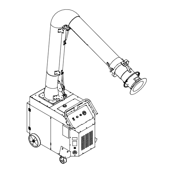
SECTION 4 − SPECIFICATIONS 4-1. Introduction The Capture series of weld fume collectors incorporates a high-volume vacuum system that uses a high efficiency, nanofiber-media cartridge filter to collect airborne weld fume particles. Weld fumes are captured at the source by a unit-mounted extraction arm. The extraction arm uses gas-shock assisted friction joints and flexible tubing to ensure the hood is placed near the source of the fumes. -
Page 19: Extraction Arm Specifications
4-4. Extraction Arm Specifications Model Arm Reach Arm Diameter XD-10 10 ft (3 m) 10 in. (254 mm) XD-12 12 ft (3.7 m) 10 in. (254 mm) 4-5. Fume Capture Zone The fume capture zone repres- ents the maximum size and shape of the fume withdrawal area in normal conditions (open room with no air movement) and... -
Page 20: Section 5 − Installation
SECTION 5 − INSTALLATION 5-1. Selecting A Location Do not move or operate unit where it could tip. Do not use this equipment to support personnel, large tools, or other material. Special installation may be re- quired where gasoline or vola- tile liquids are present −... -
Page 21: Tipping
5-2. Tipping Do not move or operate unit where it could tip. Do not move unit with extrac- tion arm extended or unit may tip. Do not move unit by pulling on extraction arm or equip- ment may tip. Use handle on fume extractor to move unit Do not use this equipment to support personnel, large... -
Page 22: Installing Extraction Arm Base Assembly
5-4. Installing Extraction Arm Base Assembly Turn Off and disconnect in- put power. Stabilize fume extractor by locking front wheels (casters). Base Assembly After installing extraction arm on cart, 3/8 in. Screw remove pin so arm moves freely. 3/8 in. Flat Washer Place base assembly on cart. -
Page 23: Connecting To Compressed Air Supply
5-5. Connecting To Compressed Air Supply Shut off air supply before disconnecting or connecting air hose. Wear protective equipment when disconnecting com- pressed air supply. Internal air tank is under pressure and will discharge when air supply is disconnected. Latch filter and close door before starting unit or oper- ating filter cleaning system. -
Page 24: Wiring Input Power Connector (Nema L16-20R)
5-6. Wiring Input Power Connector (NEMA L16-20R) Installation must meet all Na- tional and Local Codes − have only qualified persons make this installation. X Terminal Input Power Cord Select cord according to Section 5-7. Y Terminal 480 V AC, Three-Phase, 20 A, 3P4W Connector (Supplied) Cord Grip Strip insulation from end of each wire... -
Page 25: Connecting Input Power
5-8. Connecting Input Power Input 8 2012−11 / 260 889-A / 261 487-A Installation must meet all National age available at site. Connect green or green/yellow grounding and Local Codes − have only quali- conductor to disconnect device grounding Input Power Conductors (Customer fied persons make this installation. -
Page 26: Section 6 − Operation
SECTION 6 − OPERATION 6-1. Controls 260 882-A / 261 582-A Only use the fume extractor to ex- a new filter). Improper placement of the extraction tract weld fumes. Do not use the arm may affect shielding gas in the Cleaning Cycle Button fume extractor to extract hot gases weld zone and negatively impact weld... -
Page 27: Prestart Checklist (Before Welding)
6-2. Prestart Checklist (Before Welding) Do not use the fume extraction equipment unless you are sure it is correctly assembled and working properly. Check for free and easy move- ment of the extraction arm and swivel base before each use. Clean Air Outlets Filter Pressure Gauge Verify clean air outlets are not ob-... -
Page 28: Section 7 − User Servicing Instructions (Maintenance)
SECTION 7 − USER SERVICING INSTRUCTIONS (MAINTENANCE) 7-1. Routine Maintenance Disconnect Power before maintaining. Service equipment more often if used in severe conditions. n = Check Z = Change ~ = Clean l = Replace * To be done by Factory Authorized Service Agent Daily n Filter Pressure gauge. -
Page 29: Overload Protection
7-2. Overload Protection Turn off power and discon- nect input power cord. Circuit Breaker CB1 (See Parts List For Rating) CB1 protects the blower motor from overload. If CB1 opens the unit does not operate. Check breaker and re- set if open. Fuses F1, F2, And F3 (See Parts List For Rating) F1, F2, and F3 protect the controller... -
Page 30: Cleaning Filter
7-3. Cleaning Filter Latch filter and close door before starting unit or operating filter cleaning system. Do not operate unit without filter or with dirty filter. Clean or replace filter when dirty. Do not breathe the particles col- lected by the fume extractor. Wear approved safety equipment (respi- rator, gloves, long sleeve shirt) when servicing filter and spark... -
Page 31: Inspecting Filter And Spark Guard
7-4. Inspecting Filter And Spark Guard Turn off power and discon- nect input power cord. Do not operate unit without fil- ter or with dirty filter. Clean or replace the filter when dirty. Do not breathe the particles collected by the fume extrac- tor. -
Page 32: Adjusting Extraction Arm Joints
7-5. Adjusting Extraction Arm Joints Support extraction when making adjustments. Elbow joints are under ten- sion. Keep away from pinch points when making adjust- ments. When properly adjusted, the ex- traction arm should move easily but not slip from position. T-Handle Knob Use knobs to maintain arm position by increasing or decreasing joint... -
Page 33: Section 9 − Electrical Diagram
SECTION 9 − ELECTRICAL DIAGRAM 263 782-A Figure 9-1. Circuit Diagram OM-239 025 Page 28... -
Page 34: Section 10 − Parts List
SECTION 10 − PARTS LIST Hardware is common and not available unless listed. 6 − Figure 10-3 53 − See Fig10-2 264 102-A Figure 10-1. Main Assembly Item Dia. Part Mkgs. Description Quantity Figure 10-1. Main Assembly .. - Page 35 Item Dia. Part Mkgs. Description Quantity Figure 10-1. Main Assembly (Continued) ....261196 Bracket, Motor Support ......... . .
- Page 36 Hardware is common and not available unless listed. 264 101-A Figure 10-2. Blower Assembly Item Dia. Part Mkgs. Description Quantity Figure 10-2. Blower Assembly (Figure 10-1, Item 53) ....260608 Receiver, Tank Pulse Cleaning .
- Page 37 Item Dia. Part Mkgs. Description Quantity Figure 10-2. Blower Assembly (Figure 10-1, Item 53) (Continued) ....260134 Clamp, Hose 4.12 − 7.00 Clp Dia .
- Page 38 Hardware is common and not available unless listed. 264 103-A Figure 10-3. Control Box Assembly Item Dia. Part Mkgs. Description Quantity Figure 10-3. Control Box Assembly (Figure 10-1, Item 6) ....263919 Stop, Din Rail Low Profile .
- Page 39 Item Dia. Part Mkgs. Description Quantity Figure 10-3. Control Box Assembly (Figure 10-1, Item 6) (Continued) ....263921 Jumper Bar, 2 Poles Bjmi6 .........
- Page 40 Hardware is common and not available unless listed. See Fig 10-5 264 079-A Figure 10-4. Extraction Arm Base Assembly Item Dia. Part Mkgs. Description Quantity Figure 10-4. Extraction Arm Base Assembly ....+259777 Bracket, Lower Elbow Right 12.000 Collar .
- Page 41 To maintain the factory original performance of your equipment, use only Manufacturer’s Suggested Replacement Parts. Model and serial number required when ordering parts from your local distributor. Hardware is common and not available unless listed. 264 083-A Figure 10-5. Extraction Arm Tube Assembly Item Dia.
- Page 42 To maintain the factory original performance of your equipment, use only Manufacturer’s Suggested Replacement Parts. Model and serial number required when ordering parts from your local distributor. Hardware is common and not available unless listed. 264 109-A Figure 10-6. Extraction Arm Middle Tube Assembly Item Dia.
- Page 43 To maintain the factory original performance of your equipment, use only Manufacturer’s Suggested Replacement Parts. Model and serial number required when ordering parts from your local distributor. Hardware is common and not available unless listed. 264 108-A Figure 10-7. Extraction Arm Hood Assembly Item Dia.
- Page 44 Effective January 1, 2013 (Equipment with a serial number preface of MD or newer) This limited warranty supersedes all previous Miller warranties and is exclusive with no other guarantees or warranties expressed or implied. Warranty Questions? LIMITED WARRANTY − Subject to the terms and conditions below, 6 Months —...
-
Page 45: For Service
Contact the Delivering Carrier to: File a claim for loss or damage during shipment. For assistance in filing or settling claims, contact your distributor and/or equipment manufacturer’s Transportation Department. © ORIGINAL INSTRUCTIONS − PRINTED IN USA 2013 Miller Electric Mfg. Co. 2013−01...