
Manuels Connexes pour Miller Econotig


Sommaire des Matières pour Miller Econotig
- Page 1 OM-303 155 795V 2008−01 Processes Gas Tungsten Arc (TIG) Welding Shielded Metal Arc (Stick) Welding Description Arc Welding Power Source Econotig Visit our website at www.MillerWelds.com...
- Page 2 We know you don’t have time to do it any other way. That’s why when Niels Miller first started building arc welders in 1929, he made sure his products offered long-lasting value and superior quality.
-
Page 3: Table Des Matières
TABLE OF CONTENTS SECTION 1 − SAFETY PRECAUTIONS - READ BEFORE USING ........1-1. - Page 4 Notes...
-
Page 5: Section 1 − Safety Precautions - Read Before Using
SECTION 1 − SAFETY PRECAUTIONS - READ BEFORE USING som _2007−04 Protect yourself and others from injury — read and follow these precautions. 1-1. Symbol Usage DANGER! − Indicates a hazardous situation which, if Indicates special instructions. not avoided, will result in death or serious injury. The possible hazards are shown in the adjoining symbols or explained in the text. - Page 6 D Do not use welder to thaw frozen pipes. FUMES AND GASES can be hazardous. D Remove stick electrode from holder or cut off welding wire at contact tip when not in use. Welding produces fumes and gases. Breathing D Wear oil-free protective garments such as leather gloves, heavy these fumes and gases can be hazardous to your shirt, cuffless trousers, high shoes, and a cap.
-
Page 7: Additional Symbols For Installation, Operation, And Maintenance
1-3. Additional Symbols For Installation, Operation, And Maintenance FIRE OR EXPLOSION hazard. MOVING PARTS can cause injury. D Do not install or place unit on, over, or near D Keep away from moving parts such as fans. combustible surfaces. D Keep all doors, panels, covers, and guards D Do not install unit near flammables. -
Page 8: California Proposition 65 Warnings
1-4. California Proposition 65 Warnings For Gasoline Engines: Welding or cutting equipment produces fumes or gases which contain chemicals known to the State of California to Engine exhaust contains chemicals known to the State of cause birth defects and, in some cases, cancer. (California California to cause cancer, birth defects, or other reproduc- Health &... -
Page 9: Section 2 − Consignes De Sécurité − Lire Avant Utilisation
SECTION 2 − CONSIGNES DE SÉCURITÉ − LIRE AVANT UTILISATION fre_som_2007−04 Se protéger et protéger les autres contre le risque de blessure — lire et respecter ces consignes. 2-1. Symboles utilisés DANGER! − Indique une situation dangereuse qui si on Indique des instructions spécifiques. - Page 10 Il reste une TENSION DC NON NÉGLIGEABLE dans LE SOUDAGE peut provoquer un in les sources de soudage onduleur quand on a cendie ou une explosion. coupé l’alimentation. Le soudage effectué sur des conteneurs fermés tel D Arrêter les convertisseurs, débrancher le courant électrique et que des réservoirs, tambours ou des conduites peu décharger les condensateurs d’alimentation selon les instructions provoquer leur éclatement.
-
Page 11: Dangers Supplémentaires En Relation Avec L'installation, Le Fonctionnement Et La Maintenance
D Protéger les bouteilles de gaz comprimé d’une chaleur excessive, ACCUMULATIONS des chocs mécaniques, des dommages physiques, du laitier, des risquent de provoquer des blessures flammes ouvertes, des étincelles et des arcs. ou même la mort. D Placer les bouteilles debout en les fixant dans un support station- D Fermer l’alimentation du gaz protecteur en cas naire ou dans un porte-bouteilles pour les empêcher de tomber ou de non-utilisation. -
Page 12: Proposition Californienne 65 Avertissements
LES FILS DE SOUDAGE peuvent LE RAYONNEMENT HAUTE FRÉ- provoquer des blessures. QUENCE (H.F.) risque de provoquer des interférences. D Ne pas appuyer sur la gâchette avant d’en avoir reçu l’instruction. D Le rayonnement haute fréquence (H.F.) peut D Ne pas diriger le pistolet vers soi, d’autres per- provoquer des interférences avec les équipe- sonnes ou toute pièce mécanique en enga- ments de radio−navigation et de communica-... -
Page 13: Principales Normes De Sécurité
2-5. Principales normes de sécurité Safety in Welding, Cutting, and Allied Processes, ANSI Standard Z49.1, L4W 5NS (téléphone : 800-463-6727 ou à Toronto 416-747-4044, site de Global Engineering Documents (téléphone : 1-877-413-5184, site Internet : www.csa-international.org). Internet : www.global.ihs.com). Safe Practice For Occupational And Educational Eye And Face Protec- tion, ANSI Standard Z87.1, de American National Standards Institute, Recommended Safe Practices for the Preparation for Welding and Cut- 11 West 43rd Street, New York, NY 10036-8002 (téléphone :... - Page 14 OM-303 Page 10...
-
Page 15: Section 3 − Definitions
SECTION 3 − DEFINITIONS 3-1. General Precautionary Label OM-303 Page 11... -
Page 16: Symbols And Definitions
3-2. Symbols And Definitions Remote Foot/Hand Tig Welding Stick Welding High Temperature Control Output Alternating Current Direct Current Electrode Do Not Switch Electrode Positive Voltage Input Negative Under Load Amperes Electrode Gas Out Amperage Control/ Work Remote Volts Panel Rated No Load Conventional Load Maximum Effective Duty Cycle... -
Page 17: Specifications
4-2. Specifications A. 60 Hertz Models Rated Output at 20% Duty Welding Amperage Range Max. Rated Output Dimensions Cycle AC High AC Low Weight TIG: 150 A at 15 VDC (GTAW) 150 A at 15 VAC 50−165 20−50 30−160 200 V−60 A (3.6)* 12.0 H: 18 in (457 mm) 140 lb... -
Page 18: Section 5 − Installation
SECTION 5 − INSTALLATION 5-1. Selecting a Location Position unit so air can circulate. For information about sources of high-frequency see Section 9. 18 in For carts and caster kits see back 18 in (460 mm) of book or contact your distributor. (460 mm) 18 in (460 mm) -
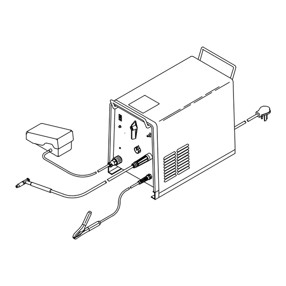
Page 19: Typical Tig Connections
5-3. Typical TIG Connections Turn Off power before mak- ing connections. Remote Control Torch Connect to receptacles as shown. Work Clamp Cylinder Chain or secure cylinder to running gear, wall, or other stationary support. Cylinder Valve Open valve slightly so gas flow blows dirt from valve. -
Page 20: Electrical Service Guide
5-4. Electrical Service Guide S-0092J Failure to follow these electrical service guide recommendations could create an electric shock or fire hazard. These recommenda- tions are for a dedicated branch circuit sized for the rated output and duty cycle of the welding power source. For 230 V models with wall receptacle, 100% duty cycle used to calculate data below. -
Page 21: Section 6 − Operation
SECTION 6 − OPERATION 6-1. Controls Ref. 155 790-F Weld Process Switch For Stick (SMAW), use control to adjust amper- For Direct Current Electrode Negative age within range selected by the Range/Polar- (DCEN), use Electrode Negative position. Use switch to select weld process. ity Switch. -
Page 22: Example Of Front Panel Amperage Control
6-2. Example of Front Panel Amperage Control In Example: Range = DC Percentage of Range = 50% Select weld process. Select range and polarity. Select percentage. Weld Amperage = 33 A DC 6-3. Example of Remote Amperage Control Select range and polarity. Select percentage. -
Page 23: Process And Material Thickness Guide Label
6-4. Process and Material Thickness Guide Label Guideline For Welding Process And Output For Material Material Thickness Material And 22 ga 20 ga 18 ga 16 ga 14 ga 12 ga 11 ga 10 ga 6 ga 2 ga − 0.033 in 0.036 in 0.048 in... -
Page 24: Section 7 − Maintenance And Troubleshooting
SECTION 7 − MAINTENANCE AND TROUBLESHOOTING 7-1. Routine Maintenance Disconnect power before maintaining. Maintain more often during severe conditions. 3 Months Replace unreadable labels. Clean and tighten weld terminals. Repair or replace cracked weld Repair or replace cracked gas cable. hose. -
Page 25: Section 8 − Electrical Diagrams
SECTION 8 − ELECTRICAL DIAGRAMS 154 141-C Figure 8-1. Circuit Diagram OM-303 Page 21... -
Page 26: Section 9 − High Frequency
SECTION 9 − HIGH FREQUENCY 9-1. Welding Processes Requiring High Frequency High-Frequency Voltage Helps arc jump air gap between torch workpiece and/or stabilize the arc. Work high_freq1 11/96 − S-0693 9-2. Incorrect Installation Weld Zone 11, 12 50 ft (15 m) S-0694 Sources of Direct High-Frequency Sources of Conduction of High... -
Page 27: Correct Installation
9-3. Correct Installation Weld Zone 50 ft (15 m) 50 ft (15 m) Ground all metal ob- jects and all wiring in welding zone using #12 AWG wire. Ground workpiece if required by codes. Nonmetal Building Metal Building Ref. S-0695 / Ref. S-0695 High-Frequency Source (welding power Conduit Joint Bonding and Grounding Metal Building Requirements... -
Page 28: Section 10 − Parts List
SECTION 10 − PARTS LIST Hardware is common and not available unless listed. 801 399-D Figure 10-1. Main Assembly OM−303 Page 24... - Page 29 Item Dia. Part Mkgs. Description Quantity Figure 10-1. Main Assembly ....154 335 BEZEL, front ........... . .
- Page 30 Item Dia. Part Mkgs. Description Quantity Figure Figure 10-1. Main Assembly (Continued) ... 157 958 LIGHT, ind wht lens 28V ......... . .
- Page 31 Effective January 1, 2008 (Equipment with a serial number preface of LJ or newer) This limited warranty supersedes all previous Miller warranties and is exclusive with no other Warranty Questions? guarantees or warranties expressed or implied. LIMITED WARRANTY − Subject to the terms and conditions...
-
Page 32: For Service
Contact the Delivering Carrier to: File a claim for loss or damage during shipment. For assistance in filing or settling claims, contact your distributor and/or equipment manufacturer’s Transportation Department. © PRINTED IN USA 2008 Miller Electric Mfg. Co. 2008−01...